1
US 20l30l40899Al
(19) United States
(12) Patent Application Publication (10) Pub. N0.2 US 2013/0140899 A1
TUUKKANEN et a].
(54)
(43) Pub. Date:
METHOD, APPARATUS FOR EMERGENCY
(52)
us. C1.
POWER SUPPLY AND DEVICE ASSOCIATED
UsPC .......................................................... .. 307/66
THERETO
(57)
?rst poWer supply line sWitch con?gured to sWitch the poWer
source between the backup poWer source and the mains
poWer, a connecting interface coupling the poWer source to an
(73) Assignee: Nokia Corporation, Espoo (Fl)
external electronic device comprising a second battery Which
is rechargeable and a second poWer supply line sWitch Which
is con?gured such that the external electronic device is able to
be poWered by either the poWer source or a second battery,
and a charging detector con?gured to detect the availability of
the mains poWer, Wherein the ?rst poWer supply line sWitch is
further con?gured to couple the backup poWer source to the
external electronic device via the connecting interface When
the mains poWer is not available such that the ?rst battery is
able to deliver poWer to the external electronic device.
(21) Appl.No.: 13/309,746
Filed:
Dec- 21 2011
Publication Classi?cation
(51)
Int. Cl.
H02] 9/00
ABSTRACT
An apparatus comprises a transformer coupled to a mains
poWer, a backup poWer source comprising a ?rst battery, a
(75) Inventors: Marko Tapio TUUKKANEN, Berlin
(DE); Markus Antti Tapio
AALTONEN, Piikkio (Fl)
(22)
Jun. 6, 2013
(2006.01)
2 \a\
)
CHARGER
.
1 '\w
Energy storage
220
,
Emergency
MOBILE DEVICE
battery
290mAh+battery
protection circuit
:
‘
222 _ \ ‘»
W
discharging
Battery charging!
J’
“X _
Cir/itch
control
7
224
\
Emergency power
enable button
\
I
r_
I
\
228 C
)
Mains power
mains power
power enable
switch
I
Switch
A
* \
V
e
\\
232
Transformer
Converts mains
(110V...220V) to
detection for
.
Charger detection
for mains power!r
,
Emergency
4
226 \ \
212 \\
21 4\\
Battery
arger
230\
*1
System 100 4*
21g
-
'
charg'ng
control
,
Battery
Patent Application Publication
Jun. 6, 2013 Sheet 1 0f 5
US 2013/0140899 A1
106
Transmitter(s)
Receiver(s)
102
104
User interface
108
GPS receiver
110
Memory
112
Circuitries
*
114
Processor(s)
Camera
116
118
Audio amplifier
SIM reader
120
122
Voltage regulator
124
FIG. 1
Patent Application Publication
Jun. 6, 2013 Sheet 2 0f 5
US 2013/0140899 A1
?f
mmm
4
f
{N
NEOI
w
i:
E3o5t9m20 9658
6E8
H
>oc9wEm
52. w
6+wEma/E0Q 05296a :25
E
LoEuFwcm;
4
NNNr/
wmwf/
W
@NNfl
wNm
6f
1'
Patent Application Publication
Jun. 6, 2013 Sheet 3 0f 5
US 2013/0140899 A1
300
/‘
Device is
powered on
302
7
Battery is low
304
A charger is
K‘
connected to
the device
306
f 308
Is the charger
Charge the
connected to the power
Yes» device battery
network?
normally
No
310
N on'fytY1 e user
/\ and request
user
interaction
314
31
Switch using
s user interaction
/_
Yesa the charger‘s
detected?
intergrated
battery
316
No
v
318
x
Allow only
Power down the
emergency
device
app|ication(s) to
run/be used
FIG.3
K
Patent Application Publication
Jun. 6, 2013 Sheet 4 0f 5
US 2013/0140899 A1
400
Device is
/
powered off
i
402
Battery is low
A charger is
/
‘404
connected to
the device
40s
\\ ///
\\\
// Is the charger \\
User powers
>< connected to the power >
on the device
\\\ network? ///
Yes
Charge the
device battery
normally
No
410/A\\
Notify the user
\
and request
user
interaction
b 414
412/A\\\ /// \\\\
/1é user interactio\n\\
\\\ detected? ///
416
\\\ ///
l
Switch using
/
the charger‘s
Yesa intergrated
battery
/A\
//
Allow only
Power down the
emergency
device
application(s) to
run/be used
418
Patent Application Publication
Jun. 6, 2013 Sheet 5 0f 5
US 2013/0140899 A1
500
Device is
/
powered off
Battery is
502
empty
/\
A charger is
connected to
K‘
504
the device
506A
i
me chargk
Charge the
/\
@onnected to the pOWe>Yes+ device battery
Networky
514
normally
N0
/_’\
+
Switch using
the charger‘s
intergrated
battery
520 /\\
User powers
on the device
510 A
\
512
/\\
\
Notify the user
and request
user
interaction
/
\
Aser interaction
\detected'g/
A
Allow only
Yesa_ emergency
applicati0n(s)
to
ru n/be used
No
Power down the
device
F|G.5
508
Jun. 6, 2013
US 2013/0140899 A1
METHOD, APPARATUS FOR EMERGENCY
POWER SUPPLY AND DEVICE ASSOCIATED
THERETO
TECHNICAL FIELD
[0001] The present application generally relates to power
supply and management of electronic devices, especially in
emergency situations.
BACKGROUND
[0002] Portable electronic devices for example mobile
phones play an important role in many emergency situations.
A simple phone call or a short message at an earliest time
could save lives and change situations. Many of the portable
electronic devices are poWer supplied by a rechargeable bat
tery. The availability of the battery poWer is a crucial point for
employing the portable electronic devices. Users alWays feel
frustrated When a device is not available because of an empty
detect the availability of the mains poWer, Wherein the ?rst
poWer supply line sWitch is further con?gured to couple the
backup poWer source to the external electronic device via the
connecting interface When the mains poWer is not available
such that the ?rst battery is able to deliver poWer to the
external electronic device.
[0006] In another exemplary embodiment, there is a pro
vided method comprising coupling a connecting interface to
an external electronic device, detecting a charging status
based partially at least on the availability of mains poWer
coupled to a transformer, and coupling a ?rst battery inside a
charger as the external poWer source to the external electronic
device When the mains poWer is not available, Wherein the
external electronic device comprises a second battery Which
is rechargeable and a second poWer supply line sWitch Which
is con?gured such that the external electronic device is able to
be poWered by either the second battery or an external poWer
source.
battery. Users may even feel as if their chargeable devices
With empty batteries are next to Worthless during mains
poWer blackout.
[0007] In a third exemplary embodiment, there is a pro
vided device comprising an internal rechargeable battery, a
charging detector coupled to an external poWer supply via a
[0003]
connecting interface, Wherein the external poWer supply
Currently there are many different existing backup
poWer solutions and devices Which can be used to provide
comprises a transformer coupled to a mains poWer and a
electricity during mains poWer blackout. For example, diesel
fueled aggregate units commonly called uninterruptible
poWer supply (UPS). Such emergency poWer unit is driven by
backup poWer source comprising a battery. The charging
detector is further con?gured to detect the availability of the
mains poWer to the external poWer supply. The provided
device further comprises an internal poWer supply line sWitch
con?gured to couple the backup poWer source to the device
such that the device is able to poWer up by the ?rst battery
diesel fuel and starts up Within the ?rst seconds of a blackout.
This solution is expensive and also heavily depends on the
amount of fuel available in the aggregate unit. Another avail
able solution is to use special battery units designed to
recharge the chargeable battery Without an actual charger.
Users can plug the special battery units into the charge port of
the device, and then from there the users Will be able to give
the device for example an hour extra running time. Such kind
of special battery units are normally disposable and pricy
Which are not commonly used by the consumers. Users can
also bring spare rechargeable battery units Which can replace
or recharge the original battery of the device. In this case the
users consume the energy from the backup battery for all
kinds of functions including emergency use When it is
needed. The users need to remember of recharging the battery
in regular basis because battery self-discharge and unit leak
age current Will sloWly discharge the battery. As a battery
ages, the users also need to keep track the status of battery by
themselves and make sure the backup battery is ready to use
When it is needed.
inside the external poWer supply When the mains poWer is not
available. The provided device is con?gured to be poWered by
either the internal rechargeable battery or the external poWer
supply controlled by the internal poWer supply line sWitch.
[0008] In a fourth exemplary embodiment, there is a pro
vided method comprising detecting an emergency status of a
device via a connecting interface to an external poWer supply
based partially at least on the availability of mains poWer,
Wherein the external poWer supply comprises a battery and a
transformer coupled to a mains poWer, and the device com
prises a internal rechargeable battery and an internal poWer
supply line sWitched con?gured such that the external elec
tronic device is poWered by either the external poWer supply
or the internal rechargeable battery. The provided method
further comprises coupling the battery in the external poWer
supply to the device When the internal rechargeable battery of
the device is loW or empty and the mains poWer is not avail
able such that the battery in the external poWer supply is able
SUMMARY
[0004] Various aspects of examples of the invention are set
out in the claims. This section is intended to be a non-limiting
overvieW of exemplary embodiments.
[0005] In an exemplary embodiment, there is a provided
to supply poWer to the device.
[0009]
In a ?fth exemplary embodiment, there is a provided
computer program product comprising a computer-readable
medium bearing computer program code embodied therein
for use With a computer, Wherein the computer program code
apparatus comprising a transformer coupled to a mains
poWer, a backup poWer source comprising a ?rst battery, a
?rst poWer supply line sWitch con?gured to sWitch the poWer
source betWeen the backup poWer source and the mains
comprises code for detecting a charger connection for mains
poWer, code for detecting the remaining poWer of a recharge
able battery in an external electronic device, code for control
ling poWer delivery from a battery in the charger directly to
poWer, a connecting interface coupling the poWer source to an
the external electronic device for running an emergency
application When the mains poWer is not available and the
external electronic device, Wherein the external electronic
device comprises a second battery Which is rechargeable and
a second poWer supply line sWitch Which is con?gured such
that the external electronic device is able to be poWered by
remaining poWer of the rechargeable battery in the external
electronic device is loW or empty or in terms of a user’s
either the poWer source or a second battery. The provided
interaction, and code for enabling poWer saving scheme in the
external electronic device if the poWer is delivered directly
apparatus further comprises a charging detector con?gured to
from the battery of the charger, Wherein the charger is coupled
Jun. 6, 2013
US 2013/0140899 A1
to the external electronic device via a connecting interface
and said connecting interface is further coupled to the mains
poWer via a transformer.
V. In the event of the SIM card being poWered in 1.8V or 3V,
the output voltage of the lithium-ion battery needs to be
doWnconverted to 1.8V or 3V so that the SIM card can be
properly operated.
BRIEF DESCRIPTION OF THE DRAWINGS
[0010] For a more complete understanding of example
embodiments of the present invention, reference is noW made
to the folloWing descriptions taken in connection With the
accompanying draWings in Which:
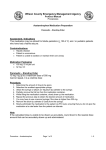
[0011]
FIG. 1 is a block diagram of an electronic device
system according to an exemplary embodiment.
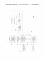
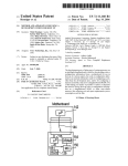
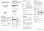
[0012] FIG. 2 is a block diagram of a charging system in
connection to a rechargeable electronic device according to
an exemplary embodiment.
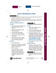
[0013]
FIG. 3 is a How diagram shoWing operations for
emergency poWer supply When an electronic device is poW
ered on and the battery in the device is loW according to an
exemplary embodiment;
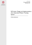
[0014]
FIG. 4 is a How diagram shoWing operations for
emergency poWer supply When an electronic device is poW
ered off and the battery in the device is loW according to an
exemplary embodiment; and
[0015]
FIG. 5 is a How diagram shoWing operations for
emergency poWer supply When an electronic device is poW
ered off and the battery in the device is empty according to an
exemplary embodiment.
[0018] A rechargeable battery is a very common poWer
source to an electronic device, for example a mobile phone.
The mobile phone Works in amount of the current battery
charge. When a rechargable battery is drained in an emer
gency situation, it is very common that user is ?rst looking for
a charger in order to start up the device. In case of mains
poWer blackout, the mobile phone operator netWorks are still
Working on backup poWer, but it is not possible to charge and
poWer on the phone using a normal charger. In this case, it is
not possible to make a call or leave SMS message even though
it is important to call during an emergency or to leave OK
message for concerned family.
[0019] It is desirable to achieve a backup poWer Which is
reliable and available in all kinds of emergency situations. It
may be feasible but not practical to put a second battery inside
a mobile phone Which Would only be used for emergency
purposes. The reason is that the mobile phone device With a
second battery Would simply become too big and thick. At the
moment, all the mobile phone manufacturers are very much
challenged from operators about the thickness of the mobile
device. For example, adding a typical 1000 mAh battery into
a product Will increase the product thickness of about 6 mm.
Another limiting factor is that some phones do not have a user
DETAILED DESCRIPTION OF THE DRAWINGS
replaceable battery. In this case a spare battery is not the
solution. HoWever, the charger form factor is not so critical at
[0016] Some exemplary embodiments of the present inven
tion and its potential advantages are understood by referring
the moment. Mobile chargers and especially universal serial
bus (U SB)-chargers are commonly provided to the consum
ers With the purchase of a mobile device and majority of
to FIGS. 1 through 5 of the draWings.
[0017] FIG. 1 is a block diagram of an electronic device
system according to an exemplary embodiment. In an
example embodiment, the electronic device may be a mobile
device, such as mobile device 100. A mobile device system
100 comprises one or more transmitters 102 and receivers 104
for transmitting and receiving data. In an embodiment, the
mobile device system 100 comprises one or more antenna 106
consumers in Europe, the United States andAsia already oWn
more than one mobile charger, and generally available to be
used With mobile devices. Based on that it may be feasible to
put an emergency battery Which could be a small battery or an
energy capacitor or a supercapacitor connected in parallel
With a small battery in the charger to keep enough electric
current for a minimum of one phone call, about 5 minutes
serving the purpose of transmitting and receiving data. The
minimum, or additionally enough for sending text message or
mobile device system 100 may further comprise a user inter
face 108, including but not limited to a graphical user inter
face. The mobile device system 100 may further comprise one
or more elements for determination of location or velocity of
[0020] FIG. 2 is a block diagram of a charging system in
connection to a rechargeable electronic device according to
an exemplary embodiment.
motion, including but not limited to a GPS (global positioning
system) receiver 110 and the GPS circuit in circuitries 114.
source to a rechargeable electronic device. In this exemplary
The mobile device system 100 may further comprise one or
more memories 112 for data and application storage and
some other functional elements, for example, a camera 118,
one or more subscriber identi?cation module (SIM) card
reader 122, and audio ampli?er 120 for driving loud speaker
or an earphone. The one or more processors 160 execute
instructions including but not limited to the energy manage
ment for driving the mobile device system 100 With various
functions. The circuitries 114 may further comprise camera
circuitry, smart card reader circuitry, and/or audio circuitry.
sharing location.
[0021]
A charging system for example a charger is a poWer
embodiment, the rechargeable electronic device is a mobile
device 1 comprising a mobile device system 100, a connector
210 to the charger 2 comprising a sWitch and a charger detec
tion unit for mains poWer, a battery charging control unit 212
and a rechargeable battery 214. The mobile device could be a
mobile phone, a laptop computer, a tablet computer or other
devices. In another exemplary embodiment, the battery
charging control unit 212 may be included in the poWer man
agement unit of the mobile device 1.
[0022] The charger 2 comprises a backup poWer source 220
Different functional elements in the systems have their oWn
comprising an energy storage emergency battery. The backup
operating voltages. A voltage regulator 124 in the mobile
poWer source 220 may further comprise a corresponding
device system 100 stabiliZes and regulates the direct current
(DC) voltage from either a battery in the mobile device or en
external poWer supply so that each functional element
receives a steady voltage With a proper level independent of
battery protection circuit. In case of GSM (global system for
mobile communications) system, a phone call is started With
a maximum poWer level of 33 dBm (in decibels (dB) refer
enced to one milliWatt (mW)) Which consumes around 2 A
hoW much poWer is draWn from the poWer source. For
(ampere) peak current from battery. Depending on the net
example, a lithium-ion battery has an output voltage up to 4.2
Work conditions, the poWer level can be either full poWer or
Jun. 6, 2013
US 2013/0140899 A1
lower. Average GSM current consumption is around 170 mA
(milliampere) and WCDMA 190 mA. This means that theo
retically 10 minutes poWer capacity for consumption in GSM
system is around 29 mAh (milliampere per hour) (i.e. 10
minutes/ 60 minutes*170 mA). A battery With poWer capacity
29 mAh Would be of very small siZe, but the peak current
might be relatively high Which means 29 mAh siZe battery has
dif?culties to deliver the around 2 A peak current during a
GSM call. For a 29 mAhbattery, the discharge rate is C:0.029
A per hour. A discharging rate of 69C:2A Would need around
inside the mobile device 1 has a similar function as the unit
222 from the charging control perspective.
[0025]
In normal use cases, the use of the emergency bat
tery 220 inside the charger 2 should be prevented to ensure
that the emergency battery 220 is fully charged. The emer
gency battery 220 should be only available in emergency
situations.
[0026] In an exemplary embodiment, the charger 2 has a
mechanical sWitch 230 for example a button on the surface
Which is enabled to be turned on by the user in emergency
1 minute to fully discharge the battery. At the moment there
situations When the mobile device battery 214 is empty.
are no lithium-ion basedbatteries available for delivering 69C
discharge current. Realistic limit at the moment is around
Emergency situations may be that there is a poWer blackout
When the charger 2 is plugged in the mains 3 or no connection
45C. Based on the above and to have margin against the peak
current it is preferably to use a higher battery capacity for
example 10 times higher battery capacity, i.e. 290 mAh. In
this example, the discharge rate Would be in a reasonable level
~7C. There are many batteries available at the moment that
support 7C discharge rate. The battery 220 Which is located
inside the charger 2 is con?gured to supply poWer to the
mobile device 1 and keep the mobile device 1 alive With or
Without charging a certain amount of energy to the recharge
able battery 214. Taking account the design of charger for
small siZe, lithium-ion battery’ s high current discharge capa
bility, the voltage or IR drop betWeen the charger 2 and
possible loW temperature environment to the battery 214
inside the mobile device 1, it is recommended to have a
battery capacity of at least 100 mAh to 300 mAh inside the
charger 2. According to an exemplary embodiment, the emer
gency battery 220 inside the charger 2 is a rechargeable bat
tery. According to another exemplary embodiment, the inte
grated battery 220 is replaceable When it has reached its
to the poWer grid. This may be detected by the charger detec
tion unit for mains poWer 224 inside the charger 2. The
charger 2 further communicates this status to the mobile
device 1 Which is intended to be charged via a connecting
interface 232. The connecting interface 232 couples the
charger 2 With the mobile device 1 Wirelessly or via a cable.
If the mobile device 1 is poWered on, the mobile device Will
then enable a poWer saving scheme in the mobile device 1.
The poWer saving scheme may include any necessary steps to
save the available poWer to the mobile device 1 for example
turning off all Widgets, games, reducing the brightness of
screen etc. In an emergency situation, by pressing the button
230 in the charger 2, it may notify the user of the device
battery’s status on a display of the mobile device 1 and asking
if the user Wants to make an emergency call. In case the
display of the mobile device 1 is broken or the screen is shut
doWn in a poWer saving scheme, there is nothing to display on
the screen. In this case pressing the button 230 may directly
expected life time or the battery 220 is not fully or at all
usable. It is possible to detect the state and condition of the
emergency battery 220 With softWare that is running on the
mobile device 1. When user plugs the charger 2 into the
mobile device 1, the device 1 noti?es the user if the emer
gency battery 220 is Worn and needs to be replaced.
initiate an emergency call from the mobile device 1 as long as
the device 1 is connected to communication netWork.
[0027] In an exemplary embodiment, an emergency poWer
enable sWitch 230 is built in the charger detection unit for
mains poWer 224 inside the charger 2. In this case during
mains blackout, the mobile device 1 needs to be poWered on
by either the internal battery 214 With a loW level voltage or
[0023] A battery made of lithium-ion cells alWays has a
battery protection circuit, for example a passive fuse or a
device Will then enables a poWer saving scheme in the mobile
device 1, notifying the user the current status of charging and
positive temperature coe?icient (PTC) device, connected
requesting a user’s interaction, and then Waiting for user’s
con?rmation Whether to alloW the device 1 using the charg
betWeen the negative pole of the emergency battery and the
positive pole of the charger 2 Which is further connected to the
mobile device 1. The purpose of the battery protection circuit
is to limit the emergency battery discharge current to a rea
sonable level and protect safety haZards in case of misuse or
in malfunction (short circuit) during an emergency use of the
mobile device 1.
[0024] The charger 2 further comprises a transformer 228
converting the supply voltage from mains poWer 3 to a loW
voltage level suitable for an application device for example a
USB charger With an output voltage of 5V, and a battery
charging/ discharging control unit 222. The battery charging/
discharging control unit 222 comprises a battery charging
integrated circuit (IC) (not shoWn). One cell lithium-ion bat
tery charging ICs are commercially available Which may be
placed inside the charger 2 to ensure that the lithium-ion
the emergency battery 220 inside the charger. The mobile
er’s integrated battery 220 for emergency application only.
[0028] In an exemplary embodiment, there is a built-in
charger detection unit for mains poWer 210 inside the mobile
device 1. Using softWare in the poWer management unit of the
mobile device 1, it is possible to detect connection to the
mains poWer 3 through the charger by the softWare. If poWer
blackout or lack of connection to the poWer grid is detected by
the softWare, the mobile device 1 enables a poWer saving
scheme in the mobile device 1, noti?es the user of the charger
status at the user interface 108 and request a user’s interac
tion, and then Waiting for user’s con?rmation Whether to
alloW the device 1 using the charger’s integrated battery 220
for emergency application only.
[0029]
After the user has con?rmed to use the emergency
battery 220 inside the charger 2 by either physically turning
battery 220 is fully charged When the charger 2 is connected
on the mechanical emergency poWer button 230 or respond
to mains 3. When the charger is disconnected from mains 3,
the lithium-ion charging IC Will enter to a special loW poWer
mode Where the current consumption on the battery charging
IC is minimized to keep the integrated emergency battery 220
ing the requesting through the user interface 1 08 of the mobile
device 1, a sWitch 226 inside the charger 2 Will disconnect the
poWer supply from the transformer 228 and connect the
poWer supply line from the emergency battery 220 into the
charged as long as possible. The battery charging control 212
connector 210 of the mobile device 1 via the connector inter
Jun. 6, 2013
US 2013/0140899 A1
face (232). In a preferable exemplary embodiment, another
switch insider the connector 210 of the mobile device 1 Will
also sWitch the poWer line directly to the mobile device sys
tem 100. This Way the emergency battery 220 inside the
charger 2 provides poWer directly to emergency functions of
the system 100. A potential energy Waste on the charging IC
212 to the internal battery 214 of the mobile device 1 can be
saved. In another exemplary embodiment, the sWitch inside
the connector 210 of the mobile device 1 enables continuous
charging of the internal battery 214. This is not recommended
for emergency situations but respects the user’s preference
for example When user knoWs there Will be soon mains poWer
available or it is not really an emergency situation. In this case
the mobile device 1 may support all the other functions in
addition to the emergency functions. The emergency func
for emergency functions use only at 418. If no user’s interac
tion is detected, the device assumes no emergency use of the
device is needed and simply poWers doWn the device at 416.
[0033]
FIG. 5 is a How diagram shoWing operations for
emergency poWer supply When an electronic device is poW
ered off and the battery in the device is empty according to an
exemplary embodiment. In a situation that a device With a
rechargeable internal battery is poWered off at 500, and it is
detected that the internal battery is empty at 502, a charger
With an integrated emergency battery according to any of
exemplary embodiments is connected to the device at 504.
The charger or the device detects Whether the charger is
connected to the poWer grid at 506 according to any of exem
plary embodiments. The device needs to be poWered on at 520
if it is used to detect the charger connection to the poWer grid
tions may include but not limited any of making a phone call,
sending an SMS message, or sharing the location.
[0030] There are many considerations in the design of a
at 506. If the mains poWer is available, the charger charges the
device battery normally at 508. OtherWise, the poWer supply
charging system integrated With an emergency battery, for
example, the voltage or IR drop betWeen charger and device
battery should be minimized. The charger Wire connected to
the phone device and other internal electronics should be
the charger’s integrated battery can be used to supply poWer
lines in both the charger and the device are sWitched such that
at 514 and user can poWer on the device at 520. The device
using battery in the charger in emergency situations.
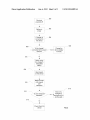
[0031] FIG. 3 is a How diagram shoWing operations for
further noti?es the user the situation and requests a user’s
interaction at 510. The user’ s interaction is detected at 512. If
the user con?rms of an emergency situation, the device is
ready for emergency functions use only at 518. If no user’s
interaction is detected, the device assumes no emergency use
emergency poWer supply When an electronic device is poW
ered on and the battery in the device is loW according to an
of the device is needed and simply poWers doWn the device at
516.
exemplary embodiment. In a situation that a device With a
[0034] Without in any Way limiting the scope, interpreta
tion, or application of the claims appearing beloW, a technical
optimiZed. The user manual should have instructions for
rechargeable internal battery is poWered on at 300, and a loW
battery is detected at 302, a charger With an integrated emer
effect of one or more of the example embodiments disclosed
gency battery according to any of exemplary embodiments is
herein is to provide a simple and reliable Way to supply poWer
for a rechargeable electronic device in emergency situations,
connected to the device at 304. The charger or the device
detects Whether the charger is connected to the poWer grid at
306 according to any of the exemplary embodiments. If it is
especially When the battery in the rechargeable electronic
detected that the mains poWer is available, the charger charges
the device battery normally at 308. Otherwise, the device
charge the battery. The supplied poWer is enough for running
noti?es the user the situation and requests a user’ s interaction
at 310. The user’s interaction is detected at 312. If the user
con?rms of an emergency situation, the poWer supply lines in
both the charger and the device are sWitched such that the
charger’s integrated battery can be used to poWer up the
device is very loW or empty and no poWer is available to
emergency applications. Another technical effect of one or
more of the example embodiments disclosed herein is to
intelligently control the access to the emergency poWer sup
ply so that the emergency poWer is available When needed.
Another technical effect of one or more of the example
device at 314 for emergency functions use only at 318. If no
user’s interaction is detected, the device assumes no emer
embodiments disclosed herein is to provide a smart charger
being able to provide poWer to a rechargeable electronic
device during mains blackout or lack of connection to poWer
gency use of the device is needed and simply poWers doWn the
grids.
device at 316.
[0035] Embodiments of the present invention may be
implemented in softWare, hardWare, application logic or a
combination of softWare, hardWare and application logic. The
[0032]
FIG. 4 is a How diagram shoWing operations for
emergency poWer supply When an electronic device is poW
ered off and the battery in the device is loW according to an
softWare, application logic and/or hardWare may reside on the
exemplary embodiment. In a situation that a device With a
charger 2. If desired, part of the softWare, application logic
rechargeable internal battery is poWered off at 400, and a loW
and/or hardWare may reside on the charger 2, part of the
softWare, application logic and/or hardWare may reside on the
mobile device 1. In an example embodiment, the application
battery is detected at 402, a charger With an integrated emer
gency battery according to any of the exemplary embodi
ments is connected to the device at 404. The charger or the
logic, softWare or an instruction set is maintained on any one
device detects Whether the charger is connected to the poWer
grid at 406 according to any of the exemplary embodiments.
The device needs to be poWered on at 420 if it is used to detect
the charger’s connection to the poWer grid at 406. If the mains
of various conventional computer-readable media. In the con
text of this document, a “computer-readable medium” may be
poWer is available, the charger charges the device battery
normally at 408. Otherwise, the device noti?es the user the
situation and requests a user’s interaction at 410. The user’s
interaction is detected at 412. If the user con?rms of an
emergency situation, the poWer supply lines in both the
charger and the device are sWitched such that the charger’s
integrated battery can be used to poWer up the device at 414
any media or means that can contain, store, communicate,
propagate or transport the instructions for use by or in con
nection With an instruction execution system, apparatus, or
device, such as a computer, With one example of a computer
described and depicted in FIG. 1 or 2. A computer-readable
medium may comprise a computer-readable storage medium
that may be any media or means that can contain or store the
instructions for use by or in connection With an instruction
execution system, apparatus, or device, such as a computer.
Jun. 6, 2013
US 2013/0140899 A1
[0036] If desired, the different functions discussed herein
may be performed in a different order and/or concurrently
10.An apparatus according to claim 1, Wherein the external
electronic device is in poWer saving mode if the poWer is
With each other. Furthermore, if desired, one or more of the
above-described functions may be optional or may be com
delivered directly from the ?rst battery in the apparatus.
11. An apparatus according to claim 1, Wherein the ?rst
battery of the apparatus is replaceable.
12. An apparatus according to claim 1, Wherein the ?rst
bined.
[0037]
Although various aspects of the invention are set out
in the independent claims, other aspects of the invention
comprise other combinations of features from the described
embodiments and/ or the dependent claims With the features
of the independent claims, and not solely the combinations
explicitly set out in the claims.
[0038] It is also noted herein that While the above describes
example embodiments of the invention, these descriptions
should not be vieWed in a limiting sense. Rather, there are
several variations and modi?cations Which may be made
Without departing from the scope of the present invention as
de?ned in the appended claims.
What is claimed is:
1. An apparatus, comprising:
a transformer coupled to a mains poWer;
a backup poWer source comprising a ?rst battery;
a ?rst poWer supply line sWitch con?gured to sWitch the
poWer source betWeen the backup poWer source and the
mains poWer;
a connecting interface coupling the poWer source to an
external electronic device comprising a second battery
Which is rechargeable and a second poWer supply line
sWitch Which is con?gured such that the external elec
tronic device is able to be poWered by either the poWer
source or a second battery; and
a charging detector con?gured to detect the availability of
the mains poWer;
Wherein the ?rst poWer supply line sWitch is further con
?gured to couple the backup poWer source to the exter
nal electronic device via the connecting interface When
the mains poWer is not available such that the ?rst battery
is able to deliver poWer to the external electronic device.
2. An apparatus according to claim 1, Wherein the ?rst
battery is a rechargeable battery and the backup poWer source
is coupled to the mains poWer such that the ?rst battery is able
to be charged by the mains poWer.
3. An apparatus according to claim 2 further comprising a
controller con?gured to control charging or discharging the
?rst battery.
4. An apparatus according to claim 1, Wherein the backup
poWer source further comprises a battery protection circuit.
5. An apparatus according to claim 4, Wherein the battery
protection circuit is a fuse.
6. An apparatus according to claim 1 further comprising a
mechanical sWitch con?gured to be enabled for supplying
poWer from the ?rst battery to the external electronic device
When the mains poWer is not available and the second battery
in the external electronic device is loW or empty.
7. An apparatus according to claim 6 con?gured to run an
emergency application only When the mechanical sWitch is
enabled, Wherein the emergency application comprises a
phone call, a text message or location sharing.
8. An apparatus according to claim 1, Wherein the poWer
source is coupled to the external electronic device Wirelessly
battery of the apparatus is a one cell lithium-ion battery hav
ing energy of capacity of at least 100 mAh (milliampere per
hour) to 300 mAh.
13. A method, comprising
coupling a connecting interface to an external electronic
device comprising a second battery Which is recharge
able and a second poWer supply line sWitched Which is
con?gured such that the external electronic device is
able to be poWered by either the second battery or an
external poWer source,
detecting a charging status based partially at least on the
availability of mains poWer coupled to a transformer,
and
coupling a ?rst battery inside a charger as the external
poWer source to the external electronic device When the
mains poWer is not available.
14. A method according to claim 13 further comprising
controlling a mechanical sWitch con?gured to be enabled for
supplying poWer from the ?rst battery inside the charger
When the mains poWer is not available and the second battery
of the external electronic device is loW or empty.
15. A method according to claim 13 further comprising
notifying the user of the charging status and requesting a
user’s interaction When the mains poWer is not available.
16. A method according to claim 13 further comprising
turning the external electronic device to a poWer saving mode
if the poWer is delivered directly from the ?rst battery of the
charger.
17. A method according to claim 14 further comprising
only alloWing an emergency application to run When the
mechanical sWitch is enabled.
18. A device, comprising:
an internal rechargeable battery;
a charging detector coupled to an external poWer supply via
a connecting interface, Wherein the external poWer sup
ply comprises a transformer coupled to a mains poWer
and a backup poWer source comprising a battery, the
charging detector further con?gured to detect the avail
ability of the mains poWer to the external poWer supply;
an internal poWer supply line sWitch con?gured to couple
the backup poWer source to the device such that the
device is able to poWer up by the ?rst battery inside the
external poWer supply When the mains poWer is not
available,
Wherein the device is con?gured to be poWered by either
the internal rechargeable battery or the external poWer
supply controlled by the internal poWer supply line
sWitch.
19. A method, comprising
detecting an emergency status of a device via a connecting
electronic device and communicated to the charging detector
interface to an external poWer supply based partially at
least on the availability of mains poWer, Wherein the
external poWer supply comprises a battery and a trans
former coupled to a mains poWer, and the device com
prises a internal rechargeable battery and an internal
in the connecting interface.
poWer supply line sWitch con?gured such that the exter
via the connecting interface.
9. An apparatus according to claim 1, Wherein the avail
ability of the mains poWer is determined by the external
US 2013/0140899 A1
nal electronic device is able to be powered by either the
external power supply or the internal rechargeable bat
tery; and
coupling the battery in the external poWer supply to the
device When the internal rechargeable battery of the
device is loW or empty and the mains poWer is not
available such that the battery in the external poWer
supply is able to supply poWer to the device.
20. A computer program product comprising a computer
readable medium bearing computer program code embodied
therein for use With a computer, the computer program code
comprising:
code for detecting a charger connection for mains poWer;
code for detecting the remaining poWer of a rechargeable
battery in an external electronic device;
code for controlling poWer delivery from a battery in the
charger directly to the external electronic device for
running an emergency application When the mains
poWer is not available and the remaining poWer of the
rechargeable battery in the external electronic device is
loW or empty, and
code for enabling poWer saving scheme in the external
electronic device if the poWer is delivered directly from
the battery of the charger,
Wherein the charger is coupled to the external electronic
device via a connecting interface and said connecting
interface is further coupled to the mains poWer via a
transformer.
Jun. 6, 2013