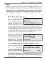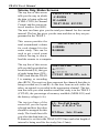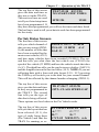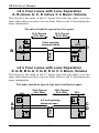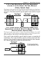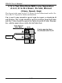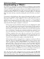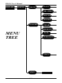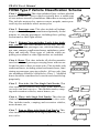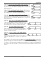
1
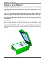
i
TRAX I User’s Manual
If you have any questions about the use of the TRAX I, please call the
following number:
215-491-4899
Monday - Friday 8:00 AM to 5:00 PM Eastern time
You may also contact us by fax at:
215-491-4889
or via e-mail at:
[email protected]
Address any correspondence to:
JAMAR Technologies, Inc.
151 Keith Valley Road
Horsham, PA 19044-1411
Volume 2.0 November 2001
ii
Quick Setup Guide for the TRAX I
1. Turn the TRAX I ON.
2. From the Main Menu, TAB to “STAT” and hold down the DO key. Check the
battery voltage (bat:X.Xv). For longer studies (week or more) the voltage should
be at least 6.4. It can be less for shorter counts, but should not be below 6.1.
Release the DO key when finished checking.
3. TAB to “Utilities” and press the DO key once. TAB to “Defaults” and press
the DO key once.
4. With “INT” flashing, press the DO key once. TAB to select the interval length
desired and press the DO key when your selection is flashing.
5. TAB to “Space” and press the DO key once. Enter the spacing of your tubes
for the study. This is only required for class, speed or gap types of studies. All of
these studies require 8 ft. This setting does not affect volume studies - if you are
doing a volume count, you do not need to set the spacing. Hit the DO key when
your selection is correct.
6. Hit the DO key twice with “Exit” flashing to return to the main menu. Note:
the default settings will remain stored in the counter for all future counts. You
will not need to set them again unless you are going to do a different type of
study.
7. From the Main Menu, press the DO key when “Count” is flashing.
8. Select the type of study you wish to do by using the TAB key and hitting DO
when your selection is flashing. The options are: Basic, Volume Only, Per Veh
(Per Vehicle) and Binned (Class/Speed/Gap).
Basic: the most complex of the studies, it time stamps every axle hit.
Use this only if you are interested in the raw data of a traffic study.
Volume Only: the simplest of the studies, it creates a study based on
one count for every two axle hits.
Per Veh (Per Vehicle): one step below Basic, it allows extensive
manipulation of the data but does not time stamp every axle hit.
Binned (Class/Speed/Gap): this study can provide Class, Speed and
Gap binned files. You can choose to do one, two, or all three of these
studies at the same time in any combination.
9. After selecting your type of study, you will be prompted to select a tube
layout. Refer to the descriptions on the TRAX I or to Chapter 4 for the appropriate selection. TAB to your selection and press the DO key to select it.
10. You will then be prompted to select a site code. Press DO with “Yes”
flashing to enter one or press DO with “None” flashing to not use a site code.
11. Press DO with “Start” flashing to begin your study!
iii
TRAX I User’s Manual
Table of Contents
Technical Support
.................................................................. ii
Quick Setup Guide for the TRAX I ................................................................ iii
Introduction to the TRAX I
............................................................... 1-1
What is the TRAX I?
............................................................... 1-2
How is the TRAX I Powered? .......................................................... 1-3
Power On, DO and TAB Functions ................................................... 1-3
Operation of the TRAX I
............................................................... 2-1
Start-up Screens
............................................................... 2-2
Main Menu
............................................................... 2-3
Utilities Menu
............................................................... 2-4
Mod
............................................................... 2-4
Clear
............................................................... 2-4
Defaults
............................................................... 2-5
Time/Date
............................................................... 2-6
Tests
............................................................... 2-7
Count Menu
............................................................... 2-8
Basic
............................................................... 2-8
Volume Only
............................................................... 2-8
Per Vehicle
............................................................... 2-8
Binned
............................................................... 2-8
Tube Layout Selection ........................................................2-9
Site Code
.............................................................2-10
Count Start-up Menu .............................................................2-11
Stat
.............................................................2-11
Set Times
.............................................................2-11
Test
.............................................................2-12
Start
.............................................................2-13
Basic Data Screens ....................................................2-13
Volume Only Status Screens .....................................2-14
Per Veh Status Screens ...............................................2-15
Binned Status Screens ...............................................2-16
Ending a Count
.............................................................2-18
Road Tube Installation
............................................................... 3-1
Road Tube Layouts
............................................................... 4-1
Downloading the TRAX I
............................................................... 5-1
Battery Care
............................................................... 6-1
Low Speed Counting
............................................................... 7-1
Troubleshooting
............................................................... 8-1
Menu Tree & Specifications
............................................................... 9-1
Appendix
.............................................................. A-1
iv
Chapter 1 — Introduction to the TRAX I
Chapter 1
Introduction
to the TRAX I
1-1
TRAX I User’s Manual
What is the TRAX I?
The TRAX I Counter/Classifier is an automatic traffic recorder designed
and built by JAMAR Technologies, Inc. It is designed for ease of use, but
contains many options and features that are needed for comprehensive traffic
data analysis.
The TRAX I can collect data in four modes: basic (raw) data, volume only
data, per vehicle data and binned class, speed and/or gap data. These various modes allow you to go from a simple one lane volume count to a multilane, individual axle time-stamped raw data collection with the same piece
of equipment.
The TRAX I can store up to 32 different studies. It stores the type of study
done, the date and time, a site code and the data for the study. At any
convenient time, you can transfer the data to your computer or a data module through the RS-232 serial port and process the data. Reports for volume, class, speed and gap can be generated using JAMAR’s data analysis
software.
1-2
Chapter 1 — Introduction to the TRAX I
How is the TRAX I powered?
The TRAX I is powered by a rechargeable lead gel battery. Depending
upon use, batteries may last for several months before they need to be
recharged. The TRAX I displays the battery voltage when it is first turned
on. This allows you to determine if there is enough battery power to complete
a study. Generally, battery voltage should register at 6.3 VDC or higher for
a full charge. Refer to Chapter 6 Battery Care for more information on
battery maintenance. The TRAX I can also be purchased with a solar panel
option.
POWER ON, DO and TAB Functions
OFF/ON
An OFF/ON switch on top of the front panel is used to power the unit. A
four line by 20-character display helps you select the proper entries. All
options are clearly displayed, with the currently selected option flashing.
The bottom two lines of the display are used to explain the option that is
highlighted.
Two buttons are all that are used to move from menu to menu, and to select
from the various options shown on the display. One key (TAB) is used to
move the highlight to the option you want, and another is used to implement it (the DO key). In general, you press the TAB key until the option
you want is flashing, and then press the DO key. If you move the highlight
too far and overshoot the desired option, just keep pressing the TAB key
until it is re-selected.
DO
TAB
1-3
TRAX I User’s Manual
This page was intentionally left blank.
1-4
Chapter 2 — Operation of the TRAX I
Chapter 2
Operation of
the TRAX I
2-1
TRAX I User’s Manual
Start-up Screens
A four-line, 20-character LCD display, located in the middle of the
TRAX I’s front panel, is used to display current options and status.
NOTE: The display of the TRAX
I has a power-saving feature that
turns off the screen if the unit has
not been disturbed for several minutes. To bring the display back up,
simply hit any of the gray keys on
the keypad.
After you power on the TRAX I the
sign-on screen is displayed. This
shows the version number of the
firmware in the TRAX I in the lower
right-hand corner.
The second screen, as shown below, displays the tube spacing that is set in
the TRAX I, the amount of memory the counter contains, the amount of
memory remaining for new studies, the number of counts stored in memory,
the status of the battery and the time and date that is set in your TRAX I.
Tube spacing: 8.0 ft
1024K Mem: 99% Avail
Counts: 02
bat: 6.4v
TD 10:25:12
02/13/98
After a few seconds, the screen clears and the Main Menu is displayed.
2-2
Chapter 2 — Operation of the TRAX I
Main Menu
COUNT UTILITIES STAT
***** MAIN MENU ******
Press DO to Count.
TAB changes option
The Main Menu is the starting point for all of the options in the TRAX I.
The options on this screen are:
COUNT
Program a new count. When Count is selected you can
choose from BASIC, VOLUME ONLY, PER VEH(icle)
or BINNED. Depending on the mode of data collection
you have selected, you can produce reports in the software
for volume, class, speed, gap, length and following distance. Refer to the Appendix for more information on how
vehicles are classified.
UTILITIES
Perform miscellaneous operations that include the option
to download to a MODULE, CLEAR the counter, program
the DEFAULT settings, set the TIME/DATE and perform
diagnostic TESTS on the TRAX I.
STAT
Select to display available memory, counts stored, battery
power, and time/date. This is the same screen as the second one shown after turning on the TRAX I. TAB until
STAT is flashing then hold the DO key down to review the
information on this screen. Approximately five seconds
after releasing the DO key, the screen will return to the
Main Menu.
2-3
TRAX I User’s Manual
Utilities Menu
MOD CLEAR DEFAULTS
TIME/DATE TESTS EXIT
Data Module commands
Press DO key
The UTILITIES Menu contains an
assortment of operations that are
necessary and/or helpful to the operation of the TRAX I. Press the
TAB key until Utilities is flashing, then press the DO key to enter this
menu. When you have selected UTILITIES from the Main Menu the screen
shown above is displayed.
MOD
STATUS WRITE
ERASE
The Mod, or Module, option alEXIT
lows you to use a JAMAR data
Status: Data Module
module with the TRAX I. You
Press DO Key
can check the status of a module, erase a module, or download data into a module by using the module’s built-in cable to connect
to the COM port on the TRAX I. The module has a memory capacity
of four MB, and can hold multiple files from several different counters.
With this feature you can download all of your data in the field and
only have to transport the module back to your office for downloading
into the software.
STATUS
WRITE
ERASE
This option allows you to check whether there is
data currently stored in the module.
This option allows you to download data from your
TRAX I into the data module. You are asked to
verify this selection several times to make sure
this is what you want to do.
This option allows you to clear any data stored in
the module. You are asked to verify this selection
several times to make sure this is what you want
to do. Once the data has been erased it cannot be
restored.
CLEAR
Clears the memory of all data. You are given two chances to change
your mind before data is removed from the nonvolatile memory. NOTE:
Once the clearing memory process has started, you must allow the
counter to finish before turning it off. Turning the counter off be-
2-4
Chapter 2 — Operation of the TRAX I
fore the clearing process is finished will result in a file error in the
counter.
DEFAULTS
INT SPACE DATE UNITS
NOTE: The nonvolatile DT DTX DBV VEH
EXIT
memory in the TRAX I will reSelect time interval
tain the default settings you
for Binned Data
program. These settings will be
used for future traffic studies
without having to re-enter the DEFAULTS menu.
INTERVAL
Internally store data in 5, 10, 15, 30, or 60 minute
intervals. Use the TAB button to select INT and
press DO. Use TAB to highlight the number of
minutes in which you would like the data stored.
With the number flashing, press DO.
SPACE
Set the proper spacing for the tube layout you will
be using. Use the TAB button to select SPACE
and press DO. Use the keypad to enter your correct tube spacing. When finished, press DO.
NOTE: The spacing does not affect volume
studies and does not need to be changed for
volume only studies. We recommend leaving the
spacing set at 8 ft.
DATE
USA (month/day/year) or World (day/month/year)
formats.
UNITS
Select either English or Metric units.
DT/DTX
Dead time or D-Bounce for air switches. Use the
TAB button to select DT and press DO. Use the
keypad to enter in the DT and press DO when completed. Typically, 25 ms is the normal setting. The
DTX setting should only be used for very low
speed counting. Refer to Chapter 7 for more information.
2-5
TRAX I User’s Manual
DBV
VEH
Allows you to set the Distance Between Vehicles.
Enter, in feet, the longest distance between consecutive axles of the largest vehicle you would expect to see at the study site. The TRAX I will use
this number to determine if the distance between
axles could be from the same vehicle or if the distance is great enough that the axles must be from
separate vehicles. Example: setting the DBV for
36 ft. tells the TRAX I that any axles spaced at
over 36 ft. apart must be from separate vehicles.
In the example from the following diagram, a DBV
setting of 40 feet would tell the TRAX I the axles
spaced at 30 feet could be from the same vehicle,
but the axles spaced at 42 feet must be from separate vehicles.
30’
42’
DBV
DBV
The TRAX I has the ability to upload user-defined
tables for class, speed or gap data collection from
JAMAR’s data analysis software. The VEH option is used to restore the factory default tables.
The default tables are 15-70 mph by 5 mph for
speed, FHWA scheme F for class, and 2 to 26+ by
2 seconds for gap.
TIME/DATE
TAB to TIME/DATE and push DO. Set the current time and date for
your location starting with the hour. Use the CHANGE buttons (3 and
6) to correct the settings as required. Use the TAB key to move from
the hour setting to the minutes. Enter the correct number of minutes.
TAB to month and enter the number for the current month. TAB to day
and enter the day of the month. Finally, TAB to year and enter the year.
When completed, press the DO button. NOTE: The real time clock in
the TRAX I uses a 24-hour military format; i.e. 5:00 P.M. is 17:00.
2-6
Chapter 2 — Operation of the TRAX I
TESTS
MEMORY
DISPLAY
MEMORY
Press DO
KEYS S.PORT EXIT
while Memory is flashing
Test internal data
and the TRAX I automatistorage memory
cally starts testing the
memory. The test does not affect any data that is stored in the unit.
DISPLAY
To test the DISPLAY, press DO after the various
screens that are displayed.
KEYS
Press any of the keys and the TRAX I will display
the key you pressed. Press DO to exit.
SER. PORT
Plug a test connector into your serial port. The
connecter must short the 2 & 3 pins. NOTE: This
test will fail if a test connector is not used properly.
Highlight EXIT and press DO to leave the DEFAULTS Menu. With EXIT
highlighted once again, press DO to exit the UTILITIES Menu and return
to the MAIN Menu.
2-7
TRAX I User’s Manual
Count Menu
When you select COUNT from the
Main Menu, the screen shown
above is displayed. The options on
this sub-menu are:
BASIC VOLUME ONLY
PER VEH BINNED EXIT
Basic Data
Press DO to accept
Basic
The most complex of the studies, Basic (Raw) data collection involves
time stamping every axle hit. Use this only if you are interested in the
raw data of a traffic study. Selecting this type of count will take you
into the tube layout selection menu, described on the following page .
Volume Only
VOL-VEH
VOL-AXLE
If you select Volume Only you
EXIT
will be taken to the screen
Binned Veh. Counts
shown here, where you can
Press DO to select
choose a study using either the
divide-by-two technique or a
straight axle count. Select VOL-VEH for a divide-by two study, where
every two hits is counted as one. Select VOL-AXLE for an axle count,
where every hit is counted as one. After you select the type of study
you want, you will be taken to the tube layout selection menu, described on the following page .
Per Veh
Short for Per Vehicle, this study is one step below Basic. It allows
extensive manipulation of the data but does not time stamp every axle
hit. Selecting this type of study will take you into the tube layout selection menu, described on the following page.
Binned
CONT CHANGE
EXIT
This study can provide Class,
OPT= CLASS SPEED GAP
Speed and Gap binned files.
Press DO to continue
You can choose to collect only
with options shown.
one type of data, or two or three
types at one time, in any combination. Unlike the other three studies,
selecting this option does not immediately take you to the tube layout
selection menu. Instead you are taken to the screen shown above.
2-8
Chapter 2 — Operation of the TRAX I
Use this screen to select the types of data you want to collect. The
default setting is for Class, Speed and Gap. To change this setting,
press the TAB key until Change
CONT CLASS SPEED GAP
is flashing and press DO. You
OPT= CLASS SPEED GAP
will then be taken to the screen
Press DO to continue
shown to the right.
with options shown.
On the screen shown, all three
study types - class, speed and gap - are currently selected. To de-select
a study type, press the TAB key until the study you want to remove is
flashing. Then press the DO key. You will see that the study you chose
has been removed from the Options listed on the second line. To reselect a study that has been removed, press the TAB key until the selection you want is flashing. Then hit the DO key. You will see the study
you chose returned to the Options on the second line.
When you have configured the options for the types of data that you
want to collect, press the TAB key until CONT is flashing. Then press
the DO key and you will be taken into the tube layout selection menu,
described below.
Tube Layout Selection
A screen similar to the one
L1 L2 L3 L4 L7 L8 L9
shown here is displayed when
in the Tube Layout Selection
Two Channel A, B Vol
Menu. The meaning of each of
Press DO to select
the selections is displayed on
the 3rd line, when the individual option is flashing. Refer to Chapter 4 Road Tube Layouts for a
more detailed description of the individual layouts. Listed below are
the types of layouts that are available to be selected with the different
types of data collection modes:
VOLUME ONLY L1 L2 L3 L4 L7 L8 L9
CLS/SPEED/GAP L5 L6 L10 L11 L12
After you have selected the tube layout for your study, you will be
taken to the Site Code Menu.
2-9
TRAX I User’s Manual
Site Code
YES
NONE
EXIT
The data in the TRAX I includes the date and time that the
Enter num. Site Code
study was done, but no direct
Press DO to accept
information on where the study
was done. Correct use of the Site Code is a way for you to guarantee
that the data you collected at a particular site was indeed collected
there. To enter a Site Code, press DO while YES is flashing. You may
then enter a numerical code up to 12 characters using the numbered
keys on the TRAX I. If you do not wish to use a Site Code, TAB until
NONE is flashing and press DO. NOTE: Pressing DO while EXIT is
flashing will exit you out of the count setup and back to the Main
Menu.
After you have entered your Site Code, you will be taken to the Count
Start-Up Menu.
2-10
Chapter 2 — Operation of the TRAX I
Count
Start-up Menu
START STAT SET TIMES
TEST
EXIT
Press DO to select
The Count Start-Up menu allows
you to immediately begin a count,
check the status of the setup, program start and stop times for the count, or
set the TRAX I into test mode.
Stat
BASIC Startup Status
When you select STAT from the
Use TAB to advance
Count Start-up menu, you will
display screens
see a screen similar to the one
CNT:02 MEM: 95% 6.4v
shown here. Use the TAB key
to scroll through screens which give you information such as the current count number, percentage of memory available, battery voltage,
study type selected, current date and time, start/stop times and site ID.
After you have tabbed through the available screens, you will be returned to the Count Start-up Menu.
Set Times
**********IMPORTANT**********
Although the ability to set start and stop times is provided as a convenience for some users, we recommend using the continuous mode
of collection whenever possible. It is easy to edit out extra data in
the software when collecting in the continuous mode. Nothing can
be done, however, if no data is collected because the incorrect start/
stop times were programmed.
After you have selected SET
hh mm MM DD YY
TIMES from the Count StartStrt: 07 :00 01 /25 /98
Up Menu, you will see the
Stop: 08 :00 01 /31 /98
screen shown here. This is the
Use TAB& ;DO=accept
screen that you will use to select your start and stop times. Press the TAB key until the letters above
the number you want to change are flashing. Then use the Change
Keys (3 & 6) on the keyboard to program the number you want. When
this number is set, press the TAB key and the next set of letters will be
flashing. Use this procedure to set your start time and date.
2-11
TRAX I User’s Manual
When the correct time and date
are set, press the DO key and
you will see the screen shown
to the right. Follow the same
instructions used in setting the
start time to set the stop time.
Strt: 07 :00 01 /25 /98
Stop: 08 :00 01 /31 /98
hh mm MM DD YY
Use TAB& ;DO=accept
When the correct date and time
START STAT
EXIT
are entered, press the DO key
and you will be taken to the
Press DO to Start
screen shown to the right. Press
Start Time Enabled
DO while START is flashing
and the TRAX I is programmed
to begin and end recording at the times you set.
IMPORTANT: After pressing DO to Start the count, you will see one
of the status screens. Vehicles will be shown on this screen as they pass
over the tubes. However, this data is not being recorded in the memory
of the TRAX I. If you TAB through the status screens, you will see in
one of the screens the word “Wait” in the upper right hand corner. This
is telling you that the TRAX I is waiting until it reaches the start time
to begin storing data. When the data is actually being stored, the word
“Wait” will change to “Run”.
Test
START STAT
EXIT
When you select TEST from
the start-up menu you will see
Press DO to Start
the screen shown below here.
TEST MODE ENABLED
Selecting start will take you to
the status screens for the type
of study you have programmed. You will be able to observe how the
TRAX I is collecting data with the setup you have programmed.
**********IMPORTANT**********
Although you will see the data for each vehicle displayed in the
TRAX I, when you are in the TEST mode no data is being stored in
permanent memory. To end the Test mode, you must turn the TRAX
I off.
2-12
Chapter 2 — Operation of the TRAX I
Start
When you select Start from the Count Start-up menu, the TRAX I will
begin recording data. You will be shown a screen that displays the data
as it is being collected. There are several screens available for viewing
while the TRAX I is collecting data. Press the TAB key to page though
the available status screens. The following are examples of the types of
screens that are available for review depending on the study you have
programmed.
Basic Data Status Screens
The top line of this screen
L06-BASIC
RUN
gives the layout that has
A: ******
been selected (L6), the type
B: ******
of study being done (Basic)
CNT: 02 MEM:95% 6.4v
and that the TRAX I is recording data (RUN). The
next two lines represent the tubes that data is being recorded on
(A, B). As the tires from an axle strike the tubes, an asterisk is
recorded in the appropriate channel. The bottom line tells you what
number count this study is (CNT:02), the percentage of memory
available (MEM:95%) and the battery voltage (6.4v).
The top two lines of this
L6: 2 Equal Tubes
screen tell you the layout
with
spacing; 2 dir
selected and the how the
SP:8.0 ft
tubes should be arranged
for this study. The third
DT:25ms
line tells you what the tube
spacing is set for in the TRAX I (SP: 8.0 ft.). The fourth line tells
you what the dead time (or D-bounce) is set for (DT:25ms).
The top line of this screen
TD 07:13:12 02/13/98
gives the date and time as
NO START/STOP TIMES
they are set in the TRAX I.
The next two lines are used
SITE ID:
12345
to tell you if start/stop times
have been programmed. If
they have been programmed, you will see the times and dates listed.
The last line is used to tell you what site code has been programmed
for the study.
2-13
TRAX I User’s Manual
Volume Only Status Screens
The top line of this screen
CHNL CNTS Int:0001
tells you the way in which
A>B:0006
the data is being collected
B>A:0008
(CHNL CNTS, or Channel
TD 07:19:50 02/13/98
Counts) and the current interval number (Int:0001).
The next two lines give you the total per channel for the current
interval. The last line gives you the time and date as they are programmed in the TRAX I.
This screen provides the
TOTAL COUNTS
total accumulated volume
A:000006
for each channel for the
B:000008
entire study. This can be
used to get a total count
without having to download the counter to a computer.
The top line of this screen
L04-VOLUME RUN
tells you the layout that has
A:******
been selected (L4), the type
B:********
of study being done (VOLCNT:02 MEM: 99% 6.4v
UME) and that the TRAX
I is running, or recording
data (RUN). The next two lines represent the channels that data is
being recorded on (A and B). As the tires from an axle strike the
tubes, an asterisk is recorded in the appropriate channel. The bottom line tells you what number count this study is in the TRAX I
(CNT:02), the percentage of memory available (MEM:99%) and
the battery voltage (6.4v).
The top two lines of the
L3: Two Full Length
screen tell you the layout
Tubes: A>B, B>A Vol.
selected and how the tubes
should be arranged for this
DT:25ms Intv: 15 min.
study. The fourth line tells
you what the dead time (or
D-bounce) is set for in the TRAX I (DT:25ms) and what length of
interval is being used for the study (Intv:15min).
2-14
Chapter 2 — Operation of the TRAX I
The top line of this screen
TD 07:19:50 02/13/98
gives the date and time as
NO START/STOP TIMES
they are set in the TRAX I.
The next two lines are used
SITE ID:
12345
to tell you if start/stop times
have been programmed. If
they have been programmed, you will see the times and dates listed.
The last line is used to tell you what site code has been programmed
for the study.
Per Veh Status Screens
The first line of this screen
tells you which channel of
CHNL 0 AX: 2 #V:0010
data you are seeing (CHNL
CLS: 02 33 MPH A>C
0), the number of axles that
GAP: 21
14.2
have been recorded for the
most recent vehicle (AX:2)
and how many vehicles have been recorded (#V:0010). The second line tells you what class the last vehicle was (CLS:02) the
speed of the vehicle (33 MPH) and how the vehicle struck the tubes
(A>C). The third line tells you the gap between vehicles (GAP:21)
and the length between the last two axles (14.2). NOTE: If you are
collecting data with a four road tube layout (L10 - L12) pressing
the TAB key will switch you to the data for your second channel.
This will be reflected by the channel number changing (CHNL 1).
The top line of this screen
TD 07:30:17 02/13/98
gives you the date and time
OPT= CLASS SPEED GAP
as they are programmed in
the TRAX I. The second
line tells you the type of
data that is being collected.
These options are fixed when in the Per Vehicle mode.
The top line of this screen
tells you the layout that has
been selected (L11), the
type of study being done
(Per-Vehicle) and that the
TRAX I is running, or re-
L11 PER-VEHICLE RUN
A:****
C:****
B:**
D:**
CNT: 02 MEM:99% 6.4v
2-15
TRAX I User’s Manual
cording data (RUN). The next two lines represent the tubes that
data is being recorded on (A, B, C & D). As the tires from an axle
strike the tubes, an asterisk is recorded in the appropriate channel.
The bottom line tells you what number count this study is in the
TRAX I (CNT:02), the percentage of memory available
(MEM:99%) and the battery voltage.
The top two lines of this
L11: 2 (1/2 & full)
screen tell you the layout
Tube Sets; A>C B>D
selected (L11) and how the
DBV: 36.0 SP: 8.0 ft
tubes should be arranged
DT: 25ms
for this study. The third line
tells you the distance between vehicles that has been programmed into the TRAX I (DBV:
36.0) and the spacing of the tubes that has been programmed (8.0
ft). The fourth line tells you the dead time, or D-Bounce, that has
been programmed (DT: 25ms).
The top line of this screen
TD 07:13:12 02/13/98
gives the date and time as
NO START/STOP TIMES
they are set in the TRAX I.
The next two lines are used
SITE ID:
12345
to tell you if start/stop times
have been programmed. If
they have been programmed, you will see the times and dates listed.
The last line is used to tell you what site code has been programmed
for the study.
Binned Status Screens
The first line of this screen
CHNL 0 AX: 2 #V:0010
tells you which channel of
CLS: 02 33 MPH A>C
data you are seeing (CHNL
GAP: 21
14.2
0), the number of axles that
have been recorded for the
most recent vehicle (AX:2)
and how many vehicles have been recorded (#V:0010). The second line tells you what class the last vehicle was (CLS:02) the
speed of the vehicle (33 MPH) and how the vehicle struck the tubes
(A>C). The third line tells you the gap between vehicles (GAP:21)
and the length between axles (14.2).
2-16
Chapter 2 — Operation of the TRAX I
NOTE: If you are collecting data with a four road tube layout
(L10 - L12) pressing the TAB key will switch you to the data for
your second channel. This will be reflected by the channel number
changing to 1 (CHNL 1).
The top line of this screen
TD 07:30:17 02/13/98
gives you the date and time
OPT= CLASS SPEED GAP
as they are programmed in
#V0: 02
#V1: 01
the TRAX I. The second
line tells you the types of
Interval: 0001
data that have been programmed to be collected. The third line gives you the vehicle totals for each channel for the current interval. The fourth line tells
you what interval is currently being recorded.
The top line of this screen
L11 BINNED-DATA RUN
tells you the layout that has
A:****
C:****
been selected (L11), the
B:**
D:**
type of study being done
CNT:
02
MEM:99%
6.4v
(Binned-Data) and that the
TRAX I is running, or recording data (RUN). The next two lines represent the tubes that
data is being recorded on (A, B, C & D). As the tires from an axle
strike the tubes, an asterisk is recorded in the appropriate channel.
The bottom line tells you what number count this study is in the
TRAX I (CNT:02), the percentage of memory available
(MEM:99%) and the battery voltage.
The top two lines of this
L11: 2 (1/2 & full)
screen tell you the layout
Tube Sets; A>C B>D
selected (L11) and how the
DBV: 36.0 SP: 8.0 ft
tubes should be arranged
DT: 25ms
Intv: 15min
for this study. The third
line tells you the distance
between vehicles that has been programmed into the TRAX I (DBV:
36.0) and the spacing of the tubes that has been programmed (8.0
ft). The fourth line tells you the dead time, or D-Bounce, that is
programmed (DT: 25ms) and the interval length that has been programmed (Intv: 15min).
2-17
TRAX I User’s Manual
The top line of this screen
TD 07:13:12 02/13/98
gives the date and time as
NO START/STOP TIMES
they are set in the TRAX I.
The next two lines are used
SITE ID:
12345
to tell you if start/stop times
have been programmed. If
they have been programmed, you will see the times and dates listed.
The last line is used to tell you what site code has been programmed
for the study.
Ending a Count
To end a count, turn the TRAX I off. The count will be stored in the
TRAX I’s internal memory. Additional studies can then be conducted with
the unit. The TRAX I can hold up to 32 different studies in its memory.
2-18
Chapter 3 — Road Tube Installation
Chapter 3
Road Tube
Installation
3-1
TRAX I User’s Manual
Installing Road Tube
Proper road tube installation is very important for collecting accurate data
with your TRAX I. The road tube and the TRAX I’s air switches comprise
the sensing device for the unit. As with all receivers, the sensor has to be
functioning properly to record reliable information. With this in mind, examine your installations carefully and be absolutely certain that your unit
is recording data as programmed. The following in- Actual Size
stallation instructions cover round tube (.25 inside
diameter (ID) by .60 outside diameter (OD)), and
mini-tube (.187 ID by .365 OD). These directions
will assist you in placing your road tubes correctly
on the road surface with confidence and a minimum Round
Mini
of effort.
Tube
Tube
Tube Length
Tube length is very critical in order to record accurate vehicle data.
The following guidelines should be followed for all studies regardless
of simplicity. The lengths listed for each study below have shown to
provide the best results based on extensive testing.
L1, L3, L4, L5, L6, L7, L9, L10 (Long tube setups)
To encompass all types of vehicles and speeds, a tube length of
sixty (60) feet is recommended for round tube, fifty (50) feet for
mini tube. These lengths should satisfy all requirements for normal street, road, highway and interstate traffic patterns.
L2, L8, L11, L12 (Short tube, long tube setups)
To ensure the pulses from the road tubes arrive at the counter in the
proper order, the tube length must be the same from the edge of the
road to the TRAX I. This will ensure that the pulse from the short
tube arrives before the pulse from the long tube.
Example: You are using mini tube to install an L11 layout across
two lanes of traffic and each lane is twelve feet wide. In order to
ensure that the distance the air pulse has to travel from the edge of
the road to the counter is the same for all tubes, you should use 38
feet for the short tubes (A & C) and 50 feet for the long tubes (B &
D). The short tubes will be installed over only one lane (12 feet),
leaving 26 feet of tube back to the TRAX I. The long tubes will be
3-2
Chapter 3 — Road Tube Installation
installed over two lanes (24 feet), but since they are 50 feet long,
you will still have 26 feet back to the TRAX I. For round tube, the
lengths would be 48 feet for the short tubes and 60 feet for the long
tubes. It is very important that the air pulses travel over the
same distance when two or more tubes are used to record data.
To accommodate the required length of tube, brass splices may be used.
The splices are approximately three (3) inches long, hollow and do not
restrict the flow of air. Do not use the splices on the roadway itself,
only on the section of tube after the clamp nearest the TRAX I.
Tube Placement
Tubes should be placed exactly perpendicular to the flow of traffic to
prevent double counting. When using two or more tubes that must be
set at specific distances from each other, always use a tape measure or
ruler to measure from the center of each tube to determine the proper
spacing. In short tube, long tube setups, the short tube should be installed to the zone line (center of the highway). Observe traffic to be
sure that vehicles in the outer lane are not coming in contact with the
short tube.
Installation
Round Tube (.25 ID x .60 OD)
Round tube should be stretched one foot for every ten feet of roadway when being installed. Each tube should be secured at each end
of the roadway by using a galvanized C-Clamp, Chinese Finger,
Figure 8 Grip or an End Plate. Whichever is used, ensure the proper
nail size is used. Use the longer nail size (normally 2 1/2 inch or
longer) in hot weather due to the softness of the asphalt. In cold
weather applications, the asphalt becomes harder, making it more
difficult to drive in the nails. In this situation, smaller nails (1 1/2
inch) can be used.
Next, secure the tube on the traveled portion of the road surface by
using mastic. As a minimum, one piece of mastic should be placed
on the zone line (middle of the road) and two pieces of mastic
should be placed in the middle of each lane. Additional mastic
should be used as deemed necessary to prevent the tube from moving when stuck by a vehicle.
3-3
TRAX I User’s Manual
Round Tube Installation
Clamp,
End Plate,
Chinese
Finger or
Figure 8
Mastic
Clamp,
End Plate,
Chinese
Finger or
Figure 8
TRAX
MASTIC: 6” Lengths are
satisfactory
TUBE: 60 ft. lengths are recommended.
Coil any excess tube near the counter.
The tube should be stretched 1 ft. for every ten ft. of road surface.
Mini-Road Tube (.20 ID x .375 OD)
Since mini tube is smaller and lighter than standard round tube,
less hardware is required to install the tubes. Also, mini tube should
not be stretched when installed, just placed on the road.
Mini Tube Installation
Mastic or
Duct Tape
Webbing
Webbing
TRAX
Knot in
Tube
MASTIC OR DUCT
TAPE: 6” Lengths are
satisfactory
TUBE: 50 ft. lengths are recommended.
Coil any excess tube near the counter.
WEBBING: Approx. 4”
to 5” long. Loop over
tube and nail as shown
above.
Do not stretch the tube, just pull it tight to avoid any movement.
3-4
Chapter 3 — Road Tube Installation
Webbing can be used to secure the tube at each end of the roadway. You may tie a knot at the far end of the tube instead of using
an end plug or PK nail. Since the mini tube is light and low profile,
you may use duct tape or two-inch mastic to secure the tube to the
roadway. Generally, three pieces of tape/mastic are sufficient. To
reduce wear and/or breakage of the tape, do not install the tape in
the path of the vehicle tires.
When installing a short tube, long tube configuration (L2, L8, L11,
L12) you may install both tubes completely across the road and tie
a knot midway of the half tube. This eliminates nailing the half
tube on the center line which can create a safety problem for installation personnel.
Checking for Accuracy
Once your tubes are installed and you are collecting data, observe the traffic as it is being recorded to be sure everything is working correctly. If
possible, check the tubes periodically during the study to ensure they have
not been damaged and data is being recorded as programmed.
Upon completion of your data collection, remove the tubes, clamps, nails
and anything else that may be of danger to the motorists. The mastic may
be hard to remove in some instances, especially in hotter weather. In those
cases, it may be left on the highway and eventually it will blend into the
asphalt from the flow of traffic.
3-5
TRAX I User’s Manual
This page was intentionally left blank.
3-6
Chapter 4 — Road Tube Layouts
Chapter 4
Road Tube
Layouts
4-1
TRAX I User’s Manual
Road Tube Layouts for the TRAX I
The TRAX I is equipped with twelve pre-programmed tube layouts for
recording traffic data. These are designated as L1 through L12 and represent the most common types of layouts used to record traffic data.
The following are descriptions of each of the layouts, and the type of data
that can be collected with each. Each layout is different, but there are some
common principles that should be used with any layout that is chosen.
• The condition of the road tubes, the manner in which they are installed and the length of the tubes are all critical to achieving good
results. Refer to Chapter 3 Road Tube Installation for more information on this.
• A tube length of sixty (60) feet is recommended for round tube, and a
tube length of fifty (50) feet is recommended for mini tube.
• In all tube setups of more than one tube, the tube length from the end
of the road to the counter must be the same for all tubes.
• In all short tube, long tube layouts, the vehicle must strike the short
tube first.
• To collect class or speed data, a minimum of eight feet of tube spacing is required to achieve accurate results.
• For counts done in the volume only mode, the TRAX I will either do
a straight axle count or use the divide-by-two technique, in which every two axle hits will increment the TRAX I by one. In order to record
volumes on a vehicle by vehicle basis without regard to their number
of axles, you must be in the Binned mode with the appropriate hose
configuration.
• Data can be collected in the Basic mode with any of the tube layouts,
since basic data is essentially a collection of all the sensor activations
on an individual basis. However, the minimum tube spacing requirements still apply to Basic data. If a layout says volume only, that is the
only information you will be able to accurately get from it. You can
collect data in the Basic mode with an L1 layout, but you will only be
4-2
Chapter 4 — Road Tube Layouts
able to get volume data, not class, speed, etc.
• Since Basic data collection requires the time stamping of each individual axle, it requires a great deal more memory space in the TRAX I.
We strongly suggest that unless you are interested in the most basic,
raw information of a study, use either the volume only, binned or per
vehicle setting to record your data.
• The following examples of how the data is recorded do not apply to
the Basic data mode. Basic data is a collection of sensor activations
that are then later grouped into usable data by the software.
The diagrams for the following layouts assume a length of twelve feet per
lane of traffic and are shown for round tube and mini tube.
L1 ó Two Channels ó A, B ó Basic, Volume
In this layout, channel “A” and channel “B” record independently. When in
Volume mode the TRAX I can do either a straight axle count or use the
divide-by-two technique.
EXAMPLE: The TRAX I has been programmed to use the divide-by-two
technique. As a passenger car passes over the “A”, the unit records one
count. As a four axle truck passes over the “A” tube the unit records two
counts.
A
36 ft. Round
26 ft. Mini
36 ft. Round
26 ft. Mini
TRAX I
24 ft.
4-3
24 ft.
B
TRAX I User’s Manual
L2 ó Two Channels with Lane Separation
A, B minus A ó Basic, Volume
In this layout, channel “A” and channel “B” record independently. The A
tube is extended over one lane while the B tube is extended over two lanes.
At the end of each interval the A channel is subtracted from the B channel
and then each channel’s total is stored in memory. When in Volume mode
the TRAX I can do either a straight axle count or use the divide-by-two
technique.
The tubes should be spaced two feet apart.
EXAMPLE: The TRAX I has been programmed to use the divide-by-two
technique. As a car approaches the tubes in the inner lane and both front
and rear axles pass over the “A” and the “B” tube, the unit records a one in
each channel. As a second car approaches the tubes in the outer lane and
both front and rear axles pass over the “B” tube, the unit records another
one in the B channel. At the end of the interval, the total in the A channel,
one, is recorded to memory. That total is then subtracted from the B subtotal of 2, for a final B total of one. One vehicle has been recorded in each
lane of the study.
36 ft. Round
26 ft. Mini
12 ft.
A
TRAX I
2 foot spacing
between tubes
4-4
24 ft.
B
Chapter 4 — Road Tube Layouts
L3 ó Two Channels with Lane Separation
A to B, B to A ó Basic, Volume
In this layout, both tubes (A and B) are extended across the lanes to be
counted. Channel A and channel B record independent of each other. When
one tube is hit, the next hit is ignored. When in Volume mode the TRAX I
can do either a straight axle count or use the divide-by-two technique.
The tubes should be spaced four and a half inches apart.
EXAMPLE: The TRAX I has been programmed to use the divide-by-two
technique. A car is traveling southbound, approaching the tubes. As the
front and rear axles strike the A tube, a one is registered in the A channel.
The front and rear axles then strike the B tube but these hits are ignored
since the A tube has just been hit. Conversely, a car traveling northbound
will strike the B tube first (recording it in the B channel) and then have its
hits on the A tube ignored.
36 ft. Round
26 ft. Mini
24 ft.
A
B
TRAX I
4.5 inch spacing
between tubes
North
4-5
TRAX I User’s Manual
L4 ó One Channel ó A ó Volume
In this layout, one tube is extended across the lanes to be counted. When in
Volume mode the TRAX I can do either a straight axle count or use the
divide-by-two technique. This layout can be used with single direction or
bidirectional traffic; however, there is no lane separation.
36 ft. Round
26 ft. Mini
24 ft.
A
TRAX I
L5 ó One Direction, No Lane Separation
A to B ó Basic, Per Veh, Binned
(Class, Speed, Gap) ó One Direction
In this layout, both tubes (A and B) are extended across the lanes to be
studied. Channel A and channel B record dependent on each other.
The tubes should be spaced eight feet apart and be of equal length.
EXAMPLE: A car is traveling southbound, approaching the tubes. As the
vehicle passes over both the A and B tubes, the speed and class of the
vehicle are registered and a one is added to the volume data. This type of
setup does not use the divide-by-two technique or axle counting in recording volume. Each individual vehicle counts as only one.
36 ft. Round
26 ft. Mini
24 ft.
A
TRAX I
8 ft.
B
North
4-6
Chapter 4 — Road Tube Layouts
L6 ó Two Lanes, With Lane Separation
A to B, B to A ó Basic, Per Veh, Binned
(Class, Speed, Gap) ó Bidirectional
This layout is the same as the L5 layout, but provides lane separation for
bidirectional traffic.
The tubes should be spaced eight feet apart and be of equal length.
36 ft. Round
26 ft. Mini
24 ft.
A
TRAX I
8 ft.
B
L7 ó Four Lanes ó A, B, C, D ó Basic, Volume
This layout is the same as the L1 layout, but with four tubes over four
separate lanes rather than two tubes over two lanes. Refer to the L1 description for more information.
24 ft.
36 ft. Round
26 ft. Mini
36 ft. Round
26 ft. Mini
24 ft.
B
C
D
TRAX I
A
4-7
TRAX I User’s Manual
L8 ó Four Lanes with Lane Separation
A, B minus A, C, D minus C ó Basic, Volume
This layout is the same as the L2 layout, but with four tubes over four
lanes rather than two tubes over two lanes. Refer to the L2 description for
more information.
The tubes should be spaced two feet apart.
36 ft. Round
26 ft. Mini
12 ft.
2 foot spacing
between tubes
A
24 ft.
24 ft.
C
TRAX I
B
36 ft. Round
26 ft. Mini
D
12 ft.
L9 ó Four Lanes with Lane Separation
A to B, B to A, C to D, D to C ó Basic, Volume
This layout is the same as the L3 layout, but with four tubes over four
lanes rather than two tubes over two lanes. Refer to the L3 description for
more information.
The tubes should be spaced four and a half inches apart.
A
B
36 ft. Round
26 ft. Mini
36 ft. Round
26 ft. Mini
4.5 inch spacing
between tubes
TRAX I
24 ft.
4-8
24 ft.
C
D
Chapter 4 — Road Tube Layouts
L10 ó Two Directions, No Lane Separation
A to B, C to D ó Basic, Per Veh, Binned
(Class, Speed, Gap)
This layout is the same as the L5 layout, but with four tubes over four lanes
rather than two tubes over two lanes. Refer to the L5 description for more
information. The tubes should be spaced eight feet apart and be of equal
length.
24 ft.
36 ft. Round
26 ft. Mini
36 ft. Round
26 ft. Mini
A
24 ft.
D
8 ft.
8 ft.
C
TRAX I
B
L11 ó Two Lanes, One Direction With Lane
Separation ó A to C, B to D ó Basic, Per Veh,
Binned (Class, Speed, Gap)
This layout is the same as the L5 layout, but with the addition of two half
tubes (A and C) to provide lane separation. Refer to the L5 layout for further information. This layout is for single direction traffic.
The A and C tubes should be spaced eight feet apart, as should the B
and D tubes. The A tube should be spaced six inches from the B tube
and the C tube should be spaced six inches from the D tube. Remember, vehicles must always strike the short tube first.
36 ft. Round
26 ft. Mini
24 ft.
6 inch spacing from
A to B and from C to D
A
TRAX I
C
B
12 ft.
8 ft.
D
4-9
TRAX I User’s Manual
L12 ó Two Directions With Lane Separation
A to C, D to B ó Basic, Per Veh, Binned
(Class, Speed, Gap)
This layout is the same as the L11 layout, but for bidirectional traffic. Refer to the L11 layout for further information.
The A and C tubes should be spaced eight feet apart, as should the B
and D tubes. The A tube should be spaced six inches from the B tube
and the C tube should be spaced six inches from the D tube. Remember, vehicles must always strike the half tube first.
36 ft. Round
26 ft. Mini
24 ft.
6 inch spacing from
A to B and from C to D
A
TRAX I
C
B
12 ft.
8 ft.
D
4-10
Chapter 5 — Downloading the TRAX I
Chapter 5
Downloading
the TRAX I
5-1
TRAX I User’s Manual
Downloading a TRAX I
The TRAX I is designed to be downloaded to a computer or data module
using its communications (serial) port. To properly download the unit you
will need JAMAR’s data analysis software, an available serial port on your
computer, and a JAMAR universal cable, shown to the right. Note that you
cannot download a TRAX I to a computer or module while it is collecting
data. You must end any counts (by turning the unit off) before you download.
To prepare to download your data, connect the universal cable to a serial
port on your computer. Some serial ports have 25 pins and some have 9.
Generally, COM 1 is a 9 pin, COM 2 is a 25 or 9 pin. The ports may be
labeled on the computer itself with COM 1 listed as 1 or A and COM 2
listed as 2 or B. The following tips should help you to avoid problems
when download through a computer’s serial port.
1) You must correctly identify what port you are plugging the cable
into. The 25 and 9 pin connectors used for serial ports are also used for
serial or parallel printers, mice, plotters, video cards and other devices.
Just because your cable fits into a connector on your PC does not mean
it is a serial port. Consult your computer instruction manual if you
have any questions on which ports are serial ports on your computer.
2) Many computers have more than one serial port. You will need to
know which serial port you are plugging the universal cable into. Serial ports are designated as COMx where x is a number from 1 to 4.
You will need to know this number to download the unit.
3) Some devices that are plugged into a computer’s serial port will not
allow the TRAX I to download its data properly. These are devices that
require a program (called a device driver) to be running in the computer at all times. These device drivers are very self-centered, and think
that all the data coming into the serial port is for them. Mice, digitizer
boards, Palm Pilots and light pens are all devices that require these
device drivers to be running. If you have to unplug a device from the
serial port to plug your TRAX I in, or if you are using a switch box, be
sure that the device does not have a driver running in memory.
Once the universal cable is plugged into the computer, plug the BLACK
plug on the other end into the TRAX I and slide the ON/OFF switch on the
unit to the ON position. After a brief period of self diagnostics, the counter
5-2
Chapter 5 — Downloading the TRAX I
will display the Main Menu shown below.
COUNT UTILITIES STAT
***** MAIN MENU ******
Press DO to Count.
TAB changes option
This is the screen from which all downloading is done. At this point, refer
to your software manual for information on how to setup the software for
downloading. Note that the TRAX I will automatically sense whatever baud
rate you select in the software. The higher the baud rate, the faster your
data will be dumped. Most newer computers can download at 19200 or
higher.
While the data is being downloaded, the display on the TRAX I will show:
TRANSFER IN PROGRESS
COUNT:01 BLOCK:01
***********************
The computer will show the data being received in blocks. Each block
represents 4096 bytes of data. Once the data has been transferred to the
computer, you may turn the TRAX I off. Do not clear the data out of the
unit until you are certain that it has been downloaded successfully to
the computer.
5-3
TRAX I User’s Manual
This page was intentionally left blank.
5-4
Chapter 6— Battery Care
Chapter 6
Battery Care
6-1
TRAX I User’s Manual
Battery Care
The following information regarding battery care is furnished to assist you
in the use and maintenance of rechargeable batteries. Battery life is dependent on the user’s preventative maintenance procedures. Establish regular
routines for all of your batteries regardless of their usage.
A battery should not be allowed to discharge too low (5.8 volts and below).
This will cause a chemical build-up on the cells that will eventually destroy the battery. Symptoms of these conditions are:
1. The battery will not charge to its full capacity of 6.4 volts or
higher.
2. The battery will only hold its charge for a short time under load
conditions.
3. The battery will discharge faster than normal during storage
under no load.
With this in mind, leave your battery in the TRAX I until the voltage discharges to 6.0 or 5.9 volts under normal use, then recharge the battery to its
highest potential (normally from 6.4 volts and up). The battery can be
charged through the charge port with the TRAX I charger or a similar 6VDC
charger with the correct plug and polarity. The battery may also be removed for charging if desired.
Charging
**********CAUTION**********
Never plug a charger into a charge port unless you
are absolutely sure of the voltage output and polarity.
Charging a battery is very important for obvious reasons. Your TRAX
I depends on a fully charged battery to operate efficiently and to produce reliable and correct data. Batteries should not be allowed to sit in
a discharged state for any length of time. Once the battery discharges
below 5.8 volts, damage to the cells has already begun. Measure or
monitor your battery by using a voltmeter or through the counter’s
display. We recommend that the battery be recharged to its highest
charge level (usually 6.4 volts and above) once it discharges to 6.0 or
5.9 volts. A good battery may charge as high as 7.0 volts or better. A
defective battery may not charge any higher than 6.0 volts after a rea-
6-2
Chapter 6— Battery Care
sonable charge time. Charge time will vary with the level of the battery
voltage. Usually, a battery of 5.9 volts can be charged to its highest
potential in 12 hours or less.
After a battery has been charged, allow it to sit for at least 8 hours and
check the voltage again to determine if the battery maintained its charge.
Some decay is acceptable; however, if the battery falls below 6.0 volts,
recharge it for a longer period of time. If this does not improve the
charge, the battery is most likely defective and it would not be wise to
use it for any lengthy data collections. Monitor your battery voltages
frequently, charging when necessary, and you will extend the life of
your battery.
Additional Notes
• Do not expose the battery to moisture or rain.
• Do not drop, hit or abuse the battery — it may break and expose the
contents, which are highly corrosive.
• Do not short circuit battery terminals. Some batteries are protected
with self-resetting fuses, but short circuits may still cause severe damage to the battery.
• It is normal for a battery to become warm to the touch during charging.
• It is normal for a battery to “self discharge” during prolonged storage. Always fully charge a battery prior to storage. While in storage,
periodically check the batteries with a voltmeter to ensure they have
not discharged below a level that may cause permanent damage.
• Always store in a cool, dry location.
• Keep batteries away from fire and do not incinerate — they may
explode.
• Under no circumstances should you attempt to open the battery case.
• Always observe polarity when connecting your battery to any electronic/electrical device. If your device is not protected for improper
battery hookup, you may cause severe damage to the electronic circuitry. The positive terminal may be indicated by a plus (+) sign or red
mark. The negative terminal may be indicated by a minus (-) sign or
black mark.
6-3
TRAX I User’s Manual
This page was intentionally left blank.
6-4
Chapter 7— Low Speed Counting
Chapter 7
Low Speed
Counting
7-1
TRAX I User’s Manual
Low Speed Counting (Below 10 mph)
The TRAX I is capable of recording vehicle data as low as idle speeds and
above with a high degree of accuracy. Tube length, tube placement, and the
air switch D-bounce (DT) setting are important factors in achieving excellent results from this type of application. The following guidelines should
be used for low speed volume installations.
Tube Length
The total length should not exceed forty (40) feet. Shorter lengths may
be used provided the vehicle speeds do not exceed 30 mph.
Tube Placement
Tube placement should be perpendicular to the flow of traffic; however, when using a high DTX setting, a slight angle (by the tube or
angled wheels of a vehicle) will not cause the counter to double count.
Remember, this only applies to low speed counting - tubes should be
placed correctly on the roadway regardless of low or high speed counting. As a reminder, two hits on the road tube represents one count in
the volume mode. Additionally, the TRAX I will record a count even if
the front and rear tires on only one side of the vehicle passes over the
tube, as well as if both front and rear tires do.
Dead Time (DT/DTX)
The DT setting is measured in milliseconds which controls the output
pulse interval from the air switch. Typically, the pulse interval is set at
20 to 40 milliseconds for normal operation. This setting will cover
most speeds; however, speeds from idle to 10 mph will require the DT
setting to be increased. When measuring volume in a very low speed
situation, use a DTX setting of 200 to 300 milliseconds to avoid double
counting.
The above rules may be varied slightly since each tube installation for low
speed traffic counting is unique. The tube length and DT may be adjusted
to fit your specific parameters. Once you have decided on your settings,
monitor incoming data to ensure accuracy.
NOTE: Be sure to reset the DT setting once you have finished your low
speed counting. Using an incorrect DT setting for average speed traffic
will produce incorrect data.
7-2
Chapter 8— Troubleshooting
Chapter 8
Trouble
shooting
8-1
TRAX I User’s Manual
Troubleshooting
The following are some common questions/problems that can be encountered when using the TRAX I. The possible answers that are stated with
them are not necessarily the only answer, but should be checked first before contacting us. If you cannot find the answer to your problem/question,
do not hesitate to contact us. Contact information is listed on the first page
of this manual. Additional support information can also be found on
our web site at www.jamartech.com.
There is no display visible on the TRAX I.
Check that the unit is not in its power-saving mode. The display automatically goes out when the TRAX I has not been disturbed for several minutes. To bring the display back up, hit any key.
The display on the TRAX I will not come on.
The battery voltage may have gone too low to power the display. Connect
the TRAX I to a battery charger and charge for 12 hours, then see if the
display comes up. If the unit was in the field collecting data when this
problem occurred, turn the unit off, return it to your office and charge.
Even if the battery voltage was too low to power the display, it may have
been high enough to continue collecting data.
The TRAX I was set in the field to collect data but no counts have been
stored.
Check your setup procedure to see if incorrect Start/Stop times were programmed. If start/stop times have been enabled, the TRAX I must reach
the start time that has been set to begin storing data. Also check that the
real-time date and time are set correctly for your location.
When downloading, not all of the studies done are appearing.
The software used with the TRAX I will download all of the counts stored
in the unit. You will be prompted for file names for each of the studies that
are downloaded. If you assign the same name several times in a row, you
will be copying over the previously named files.
Binned (Cls/Speed/Gap) data collection is not providing all of the data
desired.
Check the TRAX I’s setup to be sure the correct data options have been
programmed.
8-2
Chapter 8— Troubleshooting
The data is not being collected in the intervals desired.
Check the Interval setting in the TRAX I’s default settings.
Not all layouts are available to be selected with the study requested.
Only certain layouts can be used depending on the mode of data collection
requested. Refer to Chapter 4 for more information.
Cannot view all of the information desired on the TRAX I display after the study has begun.
There are multiple status screens for each of the data modes. To view these
screens, use the TAB key.
Serial Port test failed.
Make sure that you are using a test connector with the proper pin configuration. The test will fail if a test connector is not used. The cable used for
downloading cannot be used as a test connector.
The data produced is not accurate.
Check the tube layout used in the field and the condition of the tubes.
Make sure the tubes were set with the proper length, spacing and perpendicular to the flow of traffic. One simple condition check of a tube that is
laid out in the field is to disconnect the tube from the TRAX I and hold the
end to your cheek. You should feel the air pulse as tires cross the tube. If
you do not, there may be a tear in the tube or it may be blocked. After
setting up a counter, always observe the display and traffic to be sure data
is being recorded properly.
The TRAX I will not download.
Check your connection between the TRAX I and the computer. Refer to
Chapter 5 Downloading the TRAX I for other items to check.
The TRAX I displays ‘File Error’ during the download process.
The counter may not have been cleared properly. Once the clearing memory
process has started, it must be allowed to finish before the counter is turned
off. If this error appears, the counter must be cleared properly before future
use.
If you are unable to find a solution to your problem, contact us
using the information located on the first page of this manual.
8-3
TRAX I User’s Manual
This page was intentionally left blank.
8-4
Chapter 9— Menu Tree & Specifications
Chapter 9
Menu Tree &
Specifications
9-1
TRAX I User’s Manual
SIGN-ON
STATUS
COUNT
BASIC
VOL. ONLY
PER VEH
BINNED
UTILITIES
CLEAR
DEFAULTS
MENU
TREE
MOD
TIME/DATE
TESTS
STAT
9-2
Chapter 9— Menu Tree & Specifications
LAYOUTS
SITE CODE START-UP
OPTIONS
CONFIRM
INT
SPACE
DATE
UNITS
DT
DBV
MEMORY
DISPLAY
KEYS
SER. PORT
9-3
TRAX I User’s Manual
TRAX I Specifications
Size — 9” X 6.5” X 4.5”
Weight — approximately 7 lbs. in a cast aluminum housing
Sensor Inputs — Two or four air switches
Memory — 1024 KB internal memory backed up by lithium battery
Power — 6 volt, 10 amp hour rechargeable lead gel battery, with solar
panel option.
Interface — RS-232 serial, 9 pin DBS socket
Temperature Range — Minus 40 F (-40 C) to 165 F (72 C)
Date Format — USA or World Time
Recording Intervals — 5, 10, 15, 30 or 60 minutes
Display — wide temperature, 4-line by 20 character LCD display
Output — binary file capable of being read by JAMAR (or compatible)
software
Data Collection — Basic, Per Vehicle, Binned (Class, Speed, Gap) and
Volume
Clock — always active real-time clock
9-4
Appendix
Appendix
A-1
TRAX I User’s Manual
FHWA Type F Vehicle Classification Scheme
Class 1 - Motorcycles. This class includes all two- or three-wheeled
motorized vehicles. These vehicles typically have a saddle-type
of seat and are steered by handlebars rather than a steering wheel.
This includes motorcycles, motor scooters, mopeds, motor-powered bicycles and three-wheel motorcycles.
Class 2 - Passenger cars. This class includes all sedans,
coupes and station wagons manufactured primarily for the
purpose of carrying passengers, including those pulling
recreational or other light trailers.
Class 3 - Pickups, Vans and other 2-axle, 4-tire single
unit vehicles. This class includes all two-axle, four tire
vehicles other than passenger cars, which includes pickups, vans, campers, small motor homes, ambulances, minibuses and carryalls. These types of vehicles which are
pulling recreational or other light trailers are included.
Class 4 - Buses. This class includes all vehicles manufactured as traditional passenger-carrying buses with two axles and six tires or three or more axles. This includes only
traditional buses, including school and transit buses, functioning as passenger-carrying vehicles. All two-axle, four
tire minibuses should be classified as Class 3. Modified
buses should be considered to be trucks and classified appropriately.
Class 5 - Two-Axle, Six-Tire Single Unit Trucks. This
class includes all vehicles on a single frame which have
two axles and dual rear tires. This includes trucks, camping and recreation vehicles, motor homes, etc.
Class 6 - Three-Axle Single Unit Trucks. This class includes all vehicles on a single frame which have three axles.
This includes trucks, camping and recreation vehicles,
motor homes, etc.
Class 7 - Four or More Axle Single Unit Trucks. This
class includes all vehicles on a single frame with four or
more axles.
A-3
Appendix
Class 8 - Four or Less Axle Single Trailer Trucks. This
class includes all vehicles with four or less axles consisting of two units, in which the pulling unit is a tractor or
single unit truck.
Class 9 - Five-Axle Single Trailer Trucks. This class includes all five-axle vehicles consisting of two units in which
the pulling unit is a tractor or single unit truck.
Class 10 - Six or More Axle Single Trailer Trucks. This
class includes all vehicles with six or more axles consisting of two units in which the pulling unit is a tractor or
single unit truck.
Class 11 - Five or Less Axle Multi-Trailer Trucks.
This class includes all vehicles with five or less
axles consisting of three or more units in which
the pulling unit is a tractor or single unit truck.
Class 12 - Six-Axle Multi-Trailer Trucks. This
class includes all six-axle vehicles consisting of
three or more units in which the pulling unit is a
tractor or single unit truck.
Class 13 - Seven or More Axle Multi-Trailer
Trucks. This class includes all vehicles with seven
or more axles consisting of three or more units in
which the pulling unit is a tractor or single unit
truck.
The TRAX I also collects data for Class 14 - Unclassified Vehicles. This class
includes all vehicles which the TRAX I could not process into one of the existing
13 classes. This data can be retained in your reports, or it can be redistributed by
the software into the existing 13 classes based on the percentages in each of those
classes.
A-4
TRAX I User’s Manual
We are pleased that you have chosen the JAMAR TRAX I for your traffic
analysis needs. We have strived to develop a unit that is easy to use and has
the options that our customers require. The TRAX I has undergone extensive testing to verify the accuracy of its operations, and each unit is road
tested before it leaves our facility. However, just like other complex electronic devices, problems can occur. We have always suggested that users
verify the continuing accuracy of any device they use. We feel verification against manual counts should be performed on an annual basis as required by the FHWA to assure proper operations and results.
Should you detect any problems with any of our products, please notify
JAMAR Technologies immediately and discontinue use of the unit until
we have verified its operation.
A-5