1
Using the TPS2410EVM
User's Guide
Literature Number: SLVU181A
October 2006 – Revised February 2012
User's Guide
SLVU181A – October 2006 – Revised February 2012
TPS2410 EVM (HPA204)
This user's guide is to facilitate operation of the TPS2410 and TPS2411 evaluation module. It is used by
an engineer or technician and supplements the TPS2410/11 data sheet, schematics, and circuit board
labeling.
1
Introduction
The TPS2410 controls an N-channel MOSFET to operate in circuit as an ideal diode. The MOSFET
source and drain voltages are monitored by TPS2410 pins A and C. The TPS2410 drives the MOSFET
gate high if VAC exceeds 10 mV, and turns the MOSFET off if VAC falls below a threshold that is both
programmable and dependent on the choice of TPS2410 or TPS2411.
The TPS2410 has a turn-off point of 2.5-mv VAC.
TPS2411 is similar to TPS2410 when RSET is open and has a resistor programmable MOSFET turn-off
point. The TPS2411 can even be set to a slightly negative shutdown allowing for some voltage back
current.
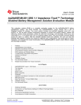
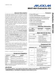
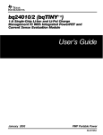
Figure 1 shows the conventional wire-OR of power supplies with diodes. Each diode D1 and D2 is
replaced by a TPS2410 and MOSFET eliminating the voltage and power loss in the diode.
The evaluation module is set up to wire-OR two power supplies for redundant power to a load using two
TPS2410s and MOSFETs. This document contains setup and user information about this evaluation
module to assist with the operation of TPS2410.
A1
C1
+V1
PS1
TPS2410
D1
GND
+V
LOAD
GND
+V1
D2
PS2
C2
A2
GND
TPS2410
One TPS2410 and
N-Channel MOSFET
Replaces One Diode
Figure 1. Conventional Wire-OR Power Supplies
2
TPS2410 EVM (HPA204)
SLVU181A – October 2006 – Revised February 2012
Submit Documentation Feedback
Copyright © 2006–2012, Texas Instruments Incorporated
Introduction
www.ti.com
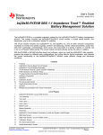
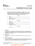
Reference Figure 2, a block diagram of the TPS2410EVM and TPS2411EVM.
• The 5-V supply is used to power status LEDs. It is jumper selected to power VDD on the TPS2410s
and the glitch circuit if the control voltage is less than 3.0 V.
• The status outputs turn on LEDs to give a visual condition of the system Fault, power good and gate
status are displayed.
• The Glitch maker, discussed in the Test Methods Section applies a 1-Ω load to the input supply for
100 μs. This disruption allows the user to scope test points and observe system recovery.
• The RSET resistor is used to program the turn-off point of the TPS2411.
• The Filter compensates for system noise.
• The UV and OV circuits set permissible limits for input operating voltage.
Output
Glitch
Maker
FET
RSET
PS 1
Channel 1
TPS2410
UV
FILTER
STATUS
OV
+ 5 V PS
Load
Output
FET
RSET
PS 2
Channel 2
TPS2410
UV
FILTER
OV
VAC
Protect
STATUS
Figure 2. EVM Block Diagram
SLVU181A – October 2006 – Revised February 2012
Submit Documentation Feedback
Copyright © 2006–2012, Texas Instruments Incorporated
TPS2410 EVM (HPA204)
3
MOSFET Configurations
2
www.ti.com
MOSFET Configurations
The TPS2410 EVM is supplied with IRL3713 MOSFETS. These MOSFETs can be replaced with user
selected parts if desired as there are alternative MOSFET footprints that accept N-channel parts in
D2PACK, DPACK, and SOIC packages. The schematic is shown in Section 4.
The MOSFETs are configured to operate as singles with only Q6 and Q13 populated as supplied. They
may be configured to operate in parallel on the PS1 channel by populating Q6 and Q5 and shorting drain
to source on Q4. Similarly, for parallel operation on the PS2 channel, populate Q13 and Q12 and short
drain to source on Q11. MOSFETs can be configured back-to-back by populating only Q4 and Q5 on
channel 1, and Q12 and Q11 on channel 2.
In single or parallel configurations, the body diode of the MOSFET limits VAC to 0.7 V. For back to back
MOSFETs, there could be a danger of exceeding the VAC operating maximum 5 V. The VAC protect circuit
is a low powered FET that is turned on when VAC approaches the maximum.
3
LED Indicators
Each channel has LED indicators for fault (FLTB), gate status (STAT), and power good (PG). Table 1
summarizes the indicators. Each is indicator is labeled on the circuit board for easy reference.
Table 1. LED Indicators
3.1
Indicator
Channel 1
Channel 2
LED On
Fault (FLTB)
D3
D8
Fault = on
Gate Status (STAT)
D2
D7
Bad gate = on
Power Good (PG)
D1
D6
Power good = on
User Circuits
There are two sections of the circuit board with plated through holes for user defined circuits.
3.2
Materials Needed – TI Supplied
•
•
•
3.3
User Supplied
•
•
•
•
•
•
•
4
TPS2410 evaluation module
TPS2410 reference design documentation
TPS2410 data sheet
2 – power supplies for wire-OR to load, up to 25 A
1 – 5-V power supply to supply EVM
Power supply cables
Load – active load, power resistors or actual load
Oscilloscope
Current probe
Differential probe
TPS2410 EVM (HPA204)
SLVU181A – October 2006 – Revised February 2012
Submit Documentation Feedback
Copyright © 2006–2012, Texas Instruments Incorporated
LED Indicators
www.ti.com
3.4
Jumper Description
Jumpers J1, J2, J13, J14
VDD can be powered by the input power supply pin A, Jump J2-2, 3 and J14-2, 3. When it is powered by
the load, pin C, jump J2-1, 2 and J14-1, 2. If A and C are less than 3 V, connect the 5 V to VDD, jumper
J1-1 to J2 -2 and J13-1 to J14-2.
J3, J15
Jumpers J3 and J15 connect a pot to the RSET pin when testing the TPS2411. These jumpers are
normally left open when testing the TPS2410.
J4, J17
Jumpers J4 and J17 are open to enable the UV and OV inputs to the TPS2410.
J6
Jumper J6 is on to connect the STAT pins together on both TPS2410 channels. When the STAT pin is
low, the turn off of the channel powering the load is de-sensitized.
J8
Jumper J8 is the gate voltage for the Glitch FET. Jump J8-2, 3 when the PS1 voltage is greater than 5 V.
Jump J8-1, 2 to use the 5-V supply when PS1 is less than 5 V.
J16
Jumper J16-2, 3 connects pin C to the load for single or parallel FETs. Connect J16-1, 2 to protect the pin
A and C inputs when output FETs are configured back-to-back.
3.5
Procedure – Jumper Set-Up
An initial jumper setup is recommended in Table 2. The module has flexibility to operate in other modes.
Change jumpers to operate in other configurations as required after getting started. After the initial setup,
reference the schematic and set jumpers as required for testing. Other J reference designators on the
schematic are simple connectors.
Table 2. Initial Jumper Settings
Jumper
Function
Selection
J1
5 V to VDD, CH1
J2
A or C to VDD, CH1
J3
Install to use RSET, CH1
Open
J4
In to disable OV channel 1
Open
J6
In to OR STAT lines
J8
5 V or PS1 to gate of PS1 pulse
J13
5 V to VDD, CH1
J14
A or C to Vdd, CH2
J15
Install to use RSET, CH2
J16
Connects the load to CH2 C or FET
J17
In to disable OV Channel 2
Comment
Open
Jumper 2 - 3
Connects A
Open
Jumper 2 - 3
Connects PS1
Open
SLVU181A – October 2006 – Revised February 2012
Submit Documentation Feedback
Jumper 2 - 3
Connects A
Open
Jumper 2 - 3
Copyright © 2006–2012, Texas Instruments Incorporated
Connects C
Open
TPS2410 EVM (HPA204)
5
LED Indicators
3.6
www.ti.com
Power Supply Connection
Connect the power supplies and load to the TPS2410 test card as shown in Table 3. Loading less than 30
A is safe for IRl3713S. The load can be a test load or the actual system load.
Table 3. Power Supply Connection
3.7
Connection
Supply
Terminal
PS1
+V
PS1, J12
PS1
PS1, J312
IN1, J5
PS1
GND
PS1GND, J10
PS2
+V
PS2, J18
PS2
GND
PS2GND, J19
5V
5V
J20-2
J20-1
5GND
GND
Load +
Load, +V
J7
Load –
GND
J11
OV and UV Setup
Set the OV and UV pots for each input voltage selected and re-adjust these pots when the input voltage
range is changed.
For this example, PS1 and PS2 are 12 V ±20 %. Set PS1 to the under-voltage set point, 9.6 V, and adjust
R13 until TP7 measures 0.6 V, reference Table 4. Set PS1 to the over-voltage set point, 14.4 V, and
adjust R12 until TP10 measures 0.6 V.
Complete this procedure for channel 2. Set the power supply voltages, PS1 and PS2, to the typical input,
12 V.
Table 4. UV and OV Setup
3.8
Supply Setting
Potentiometer
Test Point
PS1-UV
R13
TP7
PS1-OV
R12
TP10
PS2-UV
R32
TP24
PS2-OV
R31
TP26
Test Points
Table 5 lists some common test points for observation. There are more test points shown on the
schematic.
Table 5. Common Test Points
6
Function
TP Channel 1
TP Channel 2
A
TP2
TP18
C
TP9
–
GATE
TP11
TP22
OV INPUT
TP10
TP26
UV INPUT
TP7
TP24
FAULT
TP8
TP25
PG
TP4
TP20
TPS2410 EVM (HPA204)
SLVU181A – October 2006 – Revised February 2012
Submit Documentation Feedback
Copyright © 2006–2012, Texas Instruments Incorporated
LED Indicators
www.ti.com
3.9
RSET
RSET is usually used in TPS2411 and sometimes in the TPS2410 to program the MOSFET turn-off point.
The RSET calculation from the data sheet is:
æ
ö
-470.02
RRSET = ç
÷
è VOFF - 0.00314 ø
(1)
Calculate the RSET resistor. For the PS1 channel, remove jumper J3 and connect an ohm-meter from
J3-2 to GND. Adjust pot R8 for the calculated resistance value. Install the jumper J3-1, 2. Repeat for the
PS2 channel RSET Pot R26 and jumper J15. The component reference designators for each channel is
summarized in Table 6.
Table 6. RESET Resistor Setting
RSET Pot
Jumper
R8
J3
Measure
J3-2
R26
J15
J15-2
3.10 Test Methods
The EVM has many operating configurations to view the system response. The user can make
modifications to the EVM jumpers and test other set ups.
3.11 Adjust Input Power Supplies
Vary the input voltages to observe system behavior. Jumpers can be set as in Table 2. Turn the power
supplies to the application typical volts; for this paper, we will use 12 V. The load is shared between the
supplies. Both gates will be on and the power supply current meters show output. Decrease one supply
voltage slightly and note the gate on that channel pass FET turn off and the other channel FET gate
increases to keep the FET on to supply the load. Observe the FET gates with a scope. With a voltmeter,
verify VDS for the on channel to be tens of millivolts.
3.12 Glitch Maker
Remove the jumper from J5 to J12 and connect the power supply to J12. This reduces the bulk
capacitance at the PCB power supply input. Set power supplies up for equal or slight differential voltage
so that the PS1 supply is contributing to the load. Press momentary switch S1, labeled PULSE. The switch
closure places a 1-Ω load across the input power supply for 100 μs. Observe the effect of an input power
supply glitch. Scope on the MOSFET gates, load voltage, TPS2410 fault output, STAT, PG.
3.13 Load Change
A dynamic change to the load can be made by switching additional load on or off with an external switch.
Some power load test equipment can be used to dynamically change the load.
SLVU181A – October 2006 – Revised February 2012
Submit Documentation Feedback
Copyright © 2006–2012, Texas Instruments Incorporated
TPS2410 EVM (HPA204)
7
Scope Traces
4
www.ti.com
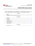
Scope Traces
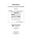
PSI - 1 V/div
GATE1 - 10 V/div
GATE2 - 10 V/div
LOAD - 1 V/div
Figure 3. PSI Shorted, Loaded
PSI - 100 mV/div
GATE2 - 5 V/div
GATE1 - 10 V/div
LOAD - 500 mV/div
Figure 4. PSI Glitched
8
TPS2410 EVM (HPA204)
SLVU181A – October 2006 – Revised February 2012
Submit Documentation Feedback
Copyright © 2006–2012, Texas Instruments Incorporated
Scope Traces
www.ti.com
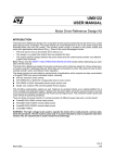
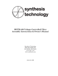
PSI - 100 mV/div
GATE1 - 10 V/div
GATE2 - 10 V/div
LOAD - 200 mV/div
Figure 5. PSI Set to Standby
GATE1 - 10 V/div
STAT - 5 V/div
FAULT - 5 V/div
PG - 5 V/div
Figure 6. PSI Set to Standby
SLVU181A – October 2006 – Revised February 2012
Submit Documentation Feedback
Copyright © 2006–2012, Texas Instruments Incorporated
TPS2410 EVM (HPA204)
9
Scope Traces
www.ti.com
GATE1 - 10 V/div
STAT - 5 V/div
FAULT - 5 V/div
PG - 5 V/div
Figure 7. PS2 On - PSI Turned On From Standby
GATE1 - 10 V/div
STAT - 5 V/div
FAULT - 5 V/div
PG - 5 V/div
Figure 8. PSI Turned On From Standby
10
TPS2410 EVM (HPA204)
SLVU181A – October 2006 – Revised February 2012
Submit Documentation Feedback
Copyright © 2006–2012, Texas Instruments Incorporated
Schematics
www.ti.com
Schematics
+
+
+
5 Volts
+
+
5
Figure 9.
SLVU181A – October 2006 – Revised February 2012
Submit Documentation Feedback
Copyright © 2006–2012, Texas Instruments Incorporated
TPS2410 EVM (HPA204)
11
Schematics
+
+
www.ti.com
Figure 10.
12
TPS2410 EVM (HPA204)
SLVU181A – October 2006 – Revised February 2012
Submit Documentation Feedback
Copyright © 2006–2012, Texas Instruments Incorporated
Schematics
www.ti.com
Figure 11.
SLVU181A – October 2006 – Revised February 2012
Submit Documentation Feedback
Copyright © 2006–2012, Texas Instruments Incorporated
TPS2410 EVM (HPA204)
13
EVM Assembly Drawings and PCB Layout
6
www.ti.com
EVM Assembly Drawings and PCB Layout
Figure 12. Top
14
TPS2410 EVM (HPA204)
SLVU181A – October 2006 – Revised February 2012
Submit Documentation Feedback
Copyright © 2006–2012, Texas Instruments Incorporated
EVM Assembly Drawings and PCB Layout
www.ti.com
Figure 13. Internal 1
SLVU181A – October 2006 – Revised February 2012
Submit Documentation Feedback
Copyright © 2006–2012, Texas Instruments Incorporated
TPS2410 EVM (HPA204)
15
EVM Assembly Drawings and PCB Layout
www.ti.com
Figure 14. Internal 2
16
TPS2410 EVM (HPA204)
SLVU181A – October 2006 – Revised February 2012
Submit Documentation Feedback
Copyright © 2006–2012, Texas Instruments Incorporated
EVM Assembly Drawings and PCB Layout
www.ti.com
Figure 15. Bottom
SLVU181A – October 2006 – Revised February 2012
Submit Documentation Feedback
Copyright © 2006–2012, Texas Instruments Incorporated
TPS2410 EVM (HPA204)
17
List of Materials
7
www.ti.com
List of Materials
Table 7. HPA204E1 List of Materials (1)
COUNT
(1)
(2)
(3)
(4)
18
RefDes
(2) (3) (4)
Description
Size
Part Number
2
C1, C18
Capacitor, ceramic, 25 V, 0.01 μF, X7R, 20%
0603
STD
1
C13
Capacitor, ceramic, 16 V, 0.1 μF, X5R, 20%
0603
STD
0
C14
Capacitor, ceramic, 25 V, X5R, 10%
0603
Do Not Populate (DNP)
1
C17
Capacitor, ceramic, 25 V, 1 μF, X5R, 20%
0805
ECJ2FB1E105M
2
C2, C19
Capacitor, ceramic, 50 V, 2200 pF, X7R, 10%
0603
STD
0
C3, C4, C21,
C22
Capacitor, ceramic, 25 V, 1 nF_DNP, X7R, 10% 0603
STD
2
C5, C20
Capacitor, ceramic, 25 V, 100 μF, 100 pF, X7R, 0603
10%
STD
7
C6, C9–C11,
C16, C23, C26
Capacitor, OSCON, SM, 100 μF, 20 V, 20%
G-Case
20SVP100M
7
C7, C8, C12,
C15, C24, C25,
C27
Capacitor, ceramic, 25 V, 22 μF, X5R, 20%
1210
ECJ4YB1E226M100M
6
D1–D3, D6–D8
Diode, LED, green
0.114 × 0.049 inch
LN1371G
4
D4, D5, D9, D10 Diode, zener, 4.3 V, 350 mW
SOT-23
BZX84C4V3T
0
E1–E6
0.038 inch
8
J1, J3, J4, J6,
Header, 2 pin, 100-mil spacing, (36-pin strip)
J9, J13, J15, J17
0.100 inch × 2
PTC36SAAN
4
J2, J8, J14, J16
Header, 3 pin, 100-mil spacing, (36-pin strip)
0.100 inch × 3
PTC36SAANl
1
J20
Terminal block, 2 pin, 6 A, 3 mm to 5 mm
0.27 × 0.25 inch
ED1514
7
J5, J7, J10–J12,
J18, J19
Screw terminal, 30 A
0.470 × 0.470 inch
8196-x
2
Q1, Q8
MOSFET, P-channel, 60 V, 90 mA, 14 Ω
SOT23
ZVP3306F0
1
Q14
Trans, P-channel, JFET, -30 V
SOT-23
SST270
0
Q15–Q17,
Q21–Q23
MOSFET, N-channel, paceholde
SO8
DNP
0
Q18–Q20,
Q24–Q26
MOSFET, N-channel, placeholder
DPAK
DNP
4
Q2, Q3, Q9, Q10 MOSFET, N-channel, 100 V, 0.17 A, 6 Ω
SOT23
BSS123c
0
Q4, Q5, Q11,
Q12
MOSFET, N-channel, 30 V, 260 A, 3 mΩ
SMD-220
IRL3713SPBF
3
Q6, Q7, Q13
MOSFET, N-channel, 30 V, 260 A, 3 mΩ
SMD-220
IRL3713SPBFV
2
R1, R19
Resistor, chip, 10 Ω, 1/10 W, 5%
0805
STD
4
R12, R13, R31,
R32
Potentiometer, 3/8 cermet, single turn, flat, 50
kΩ
0.375 sq inch
3386P-50K
1
R15
Resistor, Power Metal Strip, 1Ω, 5 W, 1%
4527
WSR5 1R0 1% R86
1
R16
Resistor, chip, 10Ω, 1/16 W, 1%
0603
STD
2
R17, R30
Resistor, chip, 1 kΩ, 1/16 W, 1%
0603
STD
1
R18
Resistor, chip, 2 kΩ, 1/10 W, 5%
0603
STD
4
R2, R3, R20,
R21
Resistor, chip, 270 Ω, 1/16 W, 1%
0603
STD
0
R4, R22
Resistor, chip, 10 kΩ_DNP, 1/16 W, 1%
0603
STD
8
R5, R6, R10,
R11, R23, R24,
R28, R29
Resistor, chip, 10 kΩ, 1/16 W, 1%
0603
STD
Pad, TH, DNP
These assemblies are ESD sensitive, ESD precautions shall be observed.
These assemblies must be clean and free from flux and all contaminants. Use of no clean flux is not acceptable.
These assemblies must comply with workmanship standards IPC-A-610 Class 2.
Ref designators marked with an asterisk ('**') cannot be substituted. All other components can be substituted with equivalent
MFG's components.
TPS2410 EVM (HPA204)
SLVU181A – October 2006 – Revised February 2012
Submit Documentation Feedback
Copyright © 2006–2012, Texas Instruments Incorporated
List of Materials
www.ti.com
Table 7. HPA204E1 List of Materials (1)
COUNT
RefDes
(2) (3) (4)
Description
(continued)
Size
Part Number
2
R7, R25
Resistor, chip, 10 Ω, 1/16 W, 1%
0603
STD
2
R8, R26
Potentiometer, 100 kΩ, 3/8 cermet, single turn,
flat
0.375 sq inch
3386P-50K
0
R9, R27
Resistor, chip, 40.2 kΩ_DNP, 1/16 W, 1%
0603
STD
1
S1
Switch, 1P1T, 20 mA, 15 V
0.240 × 0.256
EVQPAD04M
2
SH1, SH2
Short jumper
25
TP1–TP12,
TP16–TP27,
TP41
Test point, white, thru hole
0.125 × 0.125 inch
5012
10
TP13–TP15,
TP28–TP32,
TP35, TP36
Test point, SM, 0.150 × 0.090
0.185 × 0.135 inch
5016
0
TP33, TP34,
TP37–TP40
Test point, SM, 0.150 × 0.090
0.185 × 0.135 inch
5016_DNP
2
U1, U2
IC, N+1 Supply and Voltage OR Controller
PW14
TPS241xPW
0
U3, U4
PW8
DNP
1
—
PCB, 7 In × 4.25 In x 0.3 In
SLVU181A – October 2006 – Revised February 2012
Submit Documentation Feedback
Copyright © 2006–2012, Texas Instruments Incorporated
HPA204
TPS2410 EVM (HPA204)
19
IMPORTANT NOTICE
Texas Instruments Incorporated and its subsidiaries (TI) reserve the right to make corrections, modifications, enhancements, improvements,
and other changes to its products and services at any time and to discontinue any product or service without notice. Customers should
obtain the latest relevant information before placing orders and should verify that such information is current and complete. All products are
sold subject to TI’s terms and conditions of sale supplied at the time of order acknowledgment.
TI warrants performance of its hardware products to the specifications applicable at the time of sale in accordance with TI’s standard
warranty. Testing and other quality control techniques are used to the extent TI deems necessary to support this warranty. Except where
mandated by government requirements, testing of all parameters of each product is not necessarily performed.
TI assumes no liability for applications assistance or customer product design. Customers are responsible for their products and
applications using TI components. To minimize the risks associated with customer products and applications, customers should provide
adequate design and operating safeguards.
TI does not warrant or represent that any license, either express or implied, is granted under any TI patent right, copyright, mask work right,
or other TI intellectual property right relating to any combination, machine, or process in which TI products or services are used. Information
published by TI regarding third-party products or services does not constitute a license from TI to use such products or services or a
warranty or endorsement thereof. Use of such information may require a license from a third party under the patents or other intellectual
property of the third party, or a license from TI under the patents or other intellectual property of TI.
Reproduction of TI information in TI data books or data sheets is permissible only if reproduction is without alteration and is accompanied
by all associated warranties, conditions, limitations, and notices. Reproduction of this information with alteration is an unfair and deceptive
business practice. TI is not responsible or liable for such altered documentation. Information of third parties may be subject to additional
restrictions.
Resale of TI products or services with statements different from or beyond the parameters stated by TI for that product or service voids all
express and any implied warranties for the associated TI product or service and is an unfair and deceptive business practice. TI is not
responsible or liable for any such statements.
TI products are not authorized for use in safety-critical applications (such as life support) where a failure of the TI product would reasonably
be expected to cause severe personal injury or death, unless officers of the parties have executed an agreement specifically governing
such use. Buyers represent that they have all necessary expertise in the safety and regulatory ramifications of their applications, and
acknowledge and agree that they are solely responsible for all legal, regulatory and safety-related requirements concerning their products
and any use of TI products in such safety-critical applications, notwithstanding any applications-related information or support that may be
provided by TI. Further, Buyers must fully indemnify TI and its representatives against any damages arising out of the use of TI products in
such safety-critical applications.
TI products are neither designed nor intended for use in military/aerospace applications or environments unless the TI products are
specifically designated by TI as military-grade or "enhanced plastic." Only products designated by TI as military-grade meet military
specifications. Buyers acknowledge and agree that any such use of TI products which TI has not designated as military-grade is solely at
the Buyer's risk, and that they are solely responsible for compliance with all legal and regulatory requirements in connection with such use.
TI products are neither designed nor intended for use in automotive applications or environments unless the specific TI products are
designated by TI as compliant with ISO/TS 16949 requirements. Buyers acknowledge and agree that, if they use any non-designated
products in automotive applications, TI will not be responsible for any failure to meet such requirements.
Following are URLs where you can obtain information on other Texas Instruments products and application solutions:
Products
Applications
Audio
www.ti.com/audio
Automotive and Transportation www.ti.com/automotive
Amplifiers
amplifier.ti.com
Communications and Telecom www.ti.com/communications
Data Converters
dataconverter.ti.com
Computers and Peripherals
www.ti.com/computers
DLP® Products
www.dlp.com
Consumer Electronics
www.ti.com/consumer-apps
DSP
dsp.ti.com
Energy and Lighting
www.ti.com/energy
Clocks and Timers
www.ti.com/clocks
Industrial
www.ti.com/industrial
Interface
interface.ti.com
Medical
www.ti.com/medical
Logic
logic.ti.com
Security
www.ti.com/security
Power Mgmt
power.ti.com
Space, Avionics and Defense
www.ti.com/space-avionics-defense
Microcontrollers
microcontroller.ti.com
Video and Imaging
www.ti.com/video
RFID
www.ti-rfid.com
OMAP Mobile Processors
www.ti.com/omap
Wireless Connectivity
www.ti.com/wirelessconnectivity
TI E2E Community Home Page
e2e.ti.com
Mailing Address: Texas Instruments, Post Office Box 655303, Dallas, Texas 75265
Copyright © 2012, Texas Instruments Incorporated