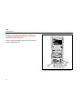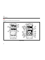
1
®
724
Temperature Calibrator
Users Manual
February 2000 Rev.1, 8/03
© 2000-2003 Fluke Corporation. All rights reserved.
All product names are trademarks of their respective companies.
LIMITED WARRANTY & LIMITATION OF LIABILITY
Each Fluke product is warranted to be free from defects in material and workmanship under normal use and service. The warranty period is
three years and begins on the date of shipment. Parts, product repairs and services are warranted for 90 days. This warranty extends only
to the original buyer or end-user customer of a Fluke authorized reseller, and does not apply to fuses, disposable batteries or to any product
which, in Fluke’s opinion, has been misused, altered, neglected, contaminated, or damaged by accident or abnormal conditions of operation
or handling. Fluke warrants that software will operate substantially in accordance with its functional specifications for 90 days and that it has
been properly recorded on non-defective media. Fluke does not warrant that software will be error free or operate without interruption.
Fluke authorized resellers shall extend this warranty on new and unused products to end-user customers only but have no authority to
extend a greater or different warranty on behalf of Fluke. Warranty support is available only if product is purchased through a Fluke
authorized sales outlet or Buyer has paid the applicable international price. Fluke reserves the right to invoice Buyer for importation costs of
repair/replacement parts when product purchased in one country is submitted for repair in another country.
Fluke’s warranty obligation is limited, at Fluke’s option, to refund of the purchase price, free of charge repair, or replacement of a defective
product which is returned to a Fluke authorized service center within the warranty period.
To obtain warranty service, contact your nearest Fluke authorized service center to obtain return authorization information, then send the
product to that service center, with a description of the difficulty, postage and insurance prepaid (FOB Destination). Fluke assumes no risk
for damage in transit. Following warranty repair, the product will be returned to Buyer, transportation prepaid (FOB Destination). If Fluke
determines that failure was caused by neglect, misuse, contamination, alteration, accident or abnormal condition of operation or handling,
including overvoltage failures caused by use outside the product’s specified rating, or normal wear and tear of mechanical components,
Fluke will provide an estimate of repair costs and obtain authorization before commencing the work. Following repair, the product will be
returned to the Buyer transportation prepaid and the Buyer will be billed for the repair and return transportation charges (FOB Shipping
Point).
THIS WARRANTY IS BUYER'S SOLE AND EXCLUSIVE REMEDY AND IS IN LIEU OF ALL OTHER WARRANTIES, EXPRESS OR
IMPLIED, INCLUDING BUT NOT LIMITED TO ANY IMPLIED WARRANTY OF MERCHANTABILITY OR FITNESS FOR A PARTICULAR
PURPOSE. FLUKE SHALL NOT BE LIABLE FOR ANY SPECIAL, INDIRECT, INCIDENTAL OR CONSEQUENTIAL DAMAGES OR
LOSSES, INCLUDING LOSS OF DATA, ARISING FROM ANY CAUSE OR THEORY.
Since some countries or states do not allow limitation of the term of an implied warranty, or exclusion or limitation of incidental or
consequential damages, the limitations and exclusions of this warranty may not apply to every buyer. If any provision of this Warranty is
held invalid or unenforceable by a court or other decision-maker of competent jurisdiction, such holding will not affect the validity or
enforceability of any other provision.
Fluke Corporation
P.O. Box 9090
Everett, WA 98206-9090
U.S.A.
11/99
Fluke Europe B.V.
P.O. Box 1186
5602 BD Eindhoven
The Netherlands
Table of Contents
Title
Introduction....................................................................................................................
Contacting Fluke............................................................................................................
Standard Equipment ......................................................................................................
Safety Information..........................................................................................................
Getting Acquainted with the Calibrator ..........................................................................
Input and Output Terminals ......................................................................................
Keys ..........................................................................................................................
Display ......................................................................................................................
Getting Started ..............................................................................................................
Shut Down Mode ...........................................................................................................
Contrast Adjustment ......................................................................................................
Using Measure Mode.....................................................................................................
Measuring Electrical Parameters (Upper Display) ....................................................
Current Measurement with Loop Power....................................................................
Measuring Electrical Parameters (Lower Display) ....................................................
Measuring Temperature............................................................................................
Using Thermocouples ..........................................................................................
i
Page
1
1
3
3
8
8
10
13
14
14
16
17
17
17
19
20
20
724
Users Manual
Using Resistance-Temperature Detectors (RTDs) ...............................................
Using Source Mode........................................................................................................
Sourcing Electrical Parameters .................................................................................
Simulating Thermocouples ........................................................................................
Simulating RTDs........................................................................................................
Setting 0 % and 100 % Output Parameters ...................................................................
Stepping and Ramping the Output.................................................................................
Manually Stepping the Output ...................................................................................
Auto Ramping the Output ..........................................................................................
Storing and Recalling Setups.........................................................................................
Calibrating a Transmitter................................................................................................
Testing an Output Device...............................................................................................
Replacing the Batteries ..................................................................................................
Replacing the Fuse ........................................................................................................
Maintenance...................................................................................................................
Cleaning the Calibrator..............................................................................................
Service Center Calibration or Repair.........................................................................
Replacement Parts ....................................................................................................
Specifications .................................................................................................................
DC Voltage Measurement .........................................................................................
DC Voltage Source....................................................................................................
DC mA Measurement ................................................................................................
Ohms Measurement ..................................................................................................
Ohms Source.............................................................................................................
Millivolt Measurement and Source* ...........................................................................
Temperature, Thermocouples ...................................................................................
Temperature, RTD Ranges, and Accuracies (ITS-90)...............................................
Loop Power Supply ...................................................................................................
ii
23
26
26
27
27
30
30
30
31
31
32
34
35
35
36
36
36
37
39
39
39
39
40
40
41
41
42
43
Temperature Calibrator
Contents (continued)
General Specifications .............................................................................................. 43
Index ....................................................................................................................................... 45
iii
724
Users Manual
iv
List of Tables
Table
Title
Page
1.
2.
3.
4.
5.
6.
7.
Summary of Source and Measure Functions........................................................................
International Symbols ...........................................................................................................
Input/Output Terminals and Connectors ...............................................................................
Key Functions .......................................................................................................................
Thermocouple Types Accepted ............................................................................................
RTD Types Accepted............................................................................................................
Replacement Parts ...............................................................................................................
2
7
9
11
21
24
37
v
724
Users Manual
vi
List of Figures
Figure
Title
Page
1.
2.
3.
4.
5.
6.
7.
8.
9.
10.
11.
12.
13.
14.
15.
16.
17.
18.
Standard Equipment .............................................................................................................
Input/Output Terminals and Connectors ...............................................................................
Keys......................................................................................................................................
Elements of a Typical Display...............................................................................................
Voltage-to-Voltage Test ........................................................................................................
Adjusting the Contrast ..........................................................................................................
Measuring Voltage and Current Output ................................................................................
Connections for Supplying Loop Power................................................................................
Measuring Electrical Parameters ..........................................................................................
Measuring Temperature with a Thermocouple .....................................................................
Measuring Temperature with an RTD, Measuring 2-, 3-, and 4-Wire Resistance ................
Electrical Sourcing Connections ...........................................................................................
Connections for Simulating a Thermocouple ........................................................................
Connection for Simulating a 3-Wire RTD..............................................................................
Calibrating a Thermocouple Transmitter...............................................................................
Calibrating a Chart Recorder ................................................................................................
Replacing the Batteries.........................................................................................................
Replacement Parts ...............................................................................................................
6
8
10
13
15
16
17
18
19
22
25
26
28
29
33
34
36
38
vii
724
Users Manual
viii
Temperature Calibrator
Introduction
Contacting Fluke
Your Fluke 724 Temperature Calibrator is a handheld,
battery-operated instrument that measures and sources a
variety of thermocouples and RTDs. See Table 1.
To order accessories, receive operating assistance, or
get the location of the nearest Fluke distributor or Service
Center, call:
In addition to the functions in Table 1, the calibrator has
the following features and functions:
•
•
•
•
A split-screen display. The upper display allows you
to measure volts and current. The lower display
allows you to measure and source volts, resistance
temperature detectors, thermocouples, and ohms.
A thermocouple (TC) input/output terminal and
internal isothermal block with automatic referencejunction temperature compensation.
Storage and recall of 8 setups.
Manual stepping and automatic stepping and
ramping.
USA: 1-888-99-FLUKE (1-888-993-5853)
Canada: 1-800-363-5853
Europe: +31 402-675-200
Japan: +81-3-3434-0181
Singapore: +65-738-5655
Anywhere in the world: +1-425-356-5500
Or, visit Fluke’s Web site at www.fluke.com.
1
724
Users Manual
Table 1. Summary of Source and Measure Functions
Function
dc V
Resistance
Thermocouple
RTD
(ResistanceTemperature
Detector)
Other functions
2
Measure
Source
0 V to30 V
0 V to10 V
0 Ω to 3200 Ω
15 Ω to 3200 Ω
Types E, J, K, T, B, R, S, L, U, N, mV
Pt100 Ω (385)
Pt100 Ω (3926)
Pt100 Ω (3916)
Pt200 Ω (385)
Pt500 Ω (385)
Pt1000 Ω (385)
Ni120
Loop supply, Step, Ramp, Memory, Dual display
Temperature Calibrator
Standard Equipment
Standard Equipment
Safety Information
The items listed below and shown in Figure 1 are included
with your calibrator. If the calibrator is damaged or
something is missing, contact the place of purchase
immediately. To order replacement parts or spares, see
the user-replaceable parts list in Table 7.
The calibrator is designed in accordance with IEC1010-1,
ANSI/ISA S82.01-1994 and CAN/CSA C22.2 No. 1010.192. Use the calibrator only as specified in this manual,
otherwise the protection provided by the calibrator may be
impaired.
•
•
•
•
•
•
TL75 test leads (one set)
Alligator clips (one set)
Stackable alligator clip test leads (one set)
724 Product Overview Manual
724 CD-ROM (contains Users Manual)
Spare fuse
A Warning identifies conditions and actions that pose
hazard(s) to the user; a Caution identifies conditions and
actions that may damage the calibrator or the equipment
under test.
International symbols used on the calibrator and in this
manual are explained in Table 2.
3
724
Users Manual
W Warning
To avoid possible electric shock or personal injury:
• Do not apply more than the rated voltage, as marked on the calibrator, between the terminals, or
between any terminal and earth ground. Maximum for all terminals is 30 V, 24 mA.
• Before each use, verify the calibrator’s operation by measuring a known voltage.
• Follow all equipment safety procedures.
• Never touch the probe to a voltage source when the test leads are plugged into the current terminals.
• Do not use the calibrator if it is damaged. Before you use the calibrator, inspect the case. Look for
cracks or missing plastic. Pay particular attention to the insulation surrounding the connectors.
• Select the proper function and range for your measurement.
• Make sure the battery door is closed and latched before you operate the calibrator.
• Remove test leads from the calibrator before you open the battery door.
• Inspect the test leads for damaged insulation or exposed metal. Check test leads continuity. Replace
damaged test leads before you use the calibrator.
• When using the probes, keep your fingers away from the probe contacts. Keep your fingers behind the
finger guards on the probes.
• Connect the common test lead before you connect the live test lead. When you disconnect test leads,
disconnect the live test lead first.
• Do not use the calibrator if it operates abnormally. Protection may be impaired. When in doubt, have the
calibrator serviced.
• Do not operate the calibrator around explosive gas, vapor, or dust.
4
Temperature Calibrator
Safety Information
W Warning
• Use only 4 AA batteries, properly installed in the calibrator case, to power the calibrator.
• Disconnect test leads before changing to another measure or source function.
• When servicing the calibrator, use only specified replacement parts.
• To avoid false readings, which could lead to possible electric shock or personal injury, replace the
batteries as soon as the battery indicator (M) appears.
Caution
To avoid possible damage to calibrator or to equipment under test:
•
Disconnect the power and discharge all high-voltage capacitors before testing resistance or continuity.
•
Use the proper jacks, function, and range for your measurement or sourcing application.
5
724
Users Manual
Alligator Clips
STORE
SETUP
100%
RECALL
25%
25%
0%
30V MAX ALL
SOURCE / MEAS
URE
TL75
Test Lead Set
3W
V
RTD
TERMINALS
MEASURE
TC
V
mA
LOOP
mA4W
COM
COM
Stackable
Test Leads
zi01f.eps
Figure 1. Standard Equipment
6
Temperature Calibrator
Safety Information
Table 2. International Symbols
AC - Alternating current
Double insulated
DC - Direct current
Battery
Earth ground
Refer to the manual for information about
this feature.
Pressure
Conforms to Canadian Standards
Association directives
O
ON/OFF
Conforms to European Union directives
7
724
Users Manual
Getting Acquainted with the Calibrator
Input and Output Terminals
724
TEMPERATURE CALIBRATOR
Figure 2 shows the calibrator input and output terminals.
Table 3 explains their use.
mA
V
MEAS
SOURCE
LOOP
˚C
V
TC
RTD
STORE
SETUP
˚F
100%
25%
RECALL
25%
0%
1
7
2
6
5
4
3
zi02f.eps
Figure 2. Input/Output Terminals and Connectors
8
Temperature Calibrator
Getting Acquainted with the Calibrator
Table 3. Input/Output Terminals and Connectors
No
Name
Description
A, B
MEASURE V, mA
terminals
Input terminals for measuring voltage, current, and supplying loop power.
C
TC input/output
Terminal for measuring or simulating thermocouples. This terminal accepts a miniature
polarized thermocouple plug with flat, in-line blades spaced 7.9 mm (0.312 in) center to
center.
D, E
SOURCE/ MEASURE
V, RTD, Ω terminals
Terminals for sourcing or measuring voltage, resistance, and RTDs.
F, G
MEASURE 3W, 4W
Terminals for performing 3W and 4W RTD measurements.
9
724
Users Manual
Keys
Figure 3 shows the calibrator keys and Table 4 explains
their use.
724
TEMPERATURE CALIBRATOR
2
724
3
4
TEMPERATURE CALIBRATOR
20
6
19
18
mA
V
7
mA
V
LOOP
LOOP
17
MEAS
SOURCE
1
˚C
V
TC
˚F
RTD
STORE
SETUP
100%
MEAS
SOURCE
5
16
25%
˚F
RTD
STORE
SETUP
25%
15
25%
14
30V MAX ALL TERMINALS
SOURCE / MEASURE
mA+
RTD
TC
COM
3W
MEASURE
V
RTD
LOOP
12
COM
10
30V MAX ALL TERMINALS
SOURCE / MEASURE
mA+
V
mA
mA4W
13
MEASURE
V
9
0%
0%
3W
8
100%
RECALL
25%
RECALL
˚C
V
TC
TC
V
mA
LOOP
mA4W
COM
11
COM
zi03f.eps
Figure 3. Keys
10
Temperature Calibrator
Getting Acquainted with the Calibrator
Table 4. Key Functions
No
Name
Description
A
O
B
V
Selects voltage measurement function in the upper display.
C
A
Selects the mA measurement function in the upper display.
D
K
Activates a 24-volt loop supply while measuring mA.
E
C
F
F
Displays temperature in degrees Celsius when in TC or RTD functions.
G
D
Displays temperature in degrees Fahrenheit when in TC or RTD functions.
H
G
I
H
Increments output by 25 % of span.
J
I
Decrements output by 25 % of span.
K
J
Turns the power on or off.
Turns backlight on or off. Turns contrast adjust mode on when powering up.
Recalls from memory a source value corresponding to 100 % of span and sets it as the source value.
Press and hold to store any source value as the 100 % value.
Recalls from memory a source value corresponding to 0 % of span and sets it as the source value.
Press and hold to store the source value as the 0 % value.
Identifies Firmware version. Press and hold J when powering up.
11
724
Users Manual
Table 4. Key Functions (cont.)
No
Name
Description
L
L
AM
OY
AM
OZ
Enables Shut Down Mode
M
XW
YZ
Increases or decreases the source level.
Cycles through the 2-, 3-, and 4-wire selections.
Moves through the eight memory locations of calibrator setups.
In Contrast Adjustment mode; up-darkens contrast, down-lightens contrast.
N
Q
Retrieves a previous calibrator setup from one of eight memory locations.
O
S
Saves the calibrator setup to one of eight memory locations. Saves Contrast Adjutment setup.
P
M
Cycles the calibrator through MEASURE and SOURCE modes in the lower display.
Q
T
Selects TC (thermocouple) measurement and sourcing function in the lower display. Repeated pushes cycle through
the thermocouple types.
R
V
Toggles between voltage, sourcing, and measuring functions in the lower display.
S
R
Selects RTD (resistance temperature detector) measurement and sourcing function in lower display. Repeated
pushes cycle through the RTD types.
T
U
Selects the ohms measurement and sourcing function.
12
E
NP
Cycles through :
Slow repeating 0 % - 100 % - 0 % ramp
Fast repeating 0 % - 100 % - 0 % ramp
Repeating 0 % - 100 % - 0 % ramp in 25 % steps
Disables Shut Down Mode
Temperature Calibrator
Getting Acquainted with the Calibrator
Display
Figure 4 shows the elements of a typical display.
Loop
Annunciator
Memory Locations
for Calibrator Setups
Low Battery
Symbol
Units
Display
Mode
Indicator
Auto
Ramp
sh07f.eps
Figure 4. Elements of a Typical Display
13
724
Users Manual
Getting Started
6.
This section acquaints you with some basic operations of
the calibrator.
Press X to increase the output to 5 V. Press and
hold G to enter 5 V as the 100 % value.
7.
Press H and I to step between 0 and 100 %
in 25 % step increments.
Proceed as follows to perform a voltage-to-voltage test:
1.
2.
3.
Connect the calibrator’s voltage output to its voltage
input as shown in Figure 5.
Press O to turn on the calibrator. Press l to
select dc voltage (upper display).
If necessary, press M for SOURCE mode (lower
display). The calibrator is still measuring dc voltage,
and you can see the active measurements in the
upper display.
4.
Press l to select dc voltage sourcing.
5.
Press Y and Z to select a digit to change. Press X
to select 1 V for the output value. Press and hold
J to enter 1 V as the 0 % value.
14
Shut Down Mode
The calibrator comes with the Shut Down mode
enabled for a time duration set to 30 minutes
(displayed for about 1 second when the calibrator is
initially turned on). When the Shut Down mode is
enabled, the calibrator will automatically shut down
after the time duration has elapsed from the time the
last key was pressed. To disable the Shut Down mode,
press O and Y simultaneously. To enable the mode,
press O and Z simultaneously. To adjust the time
duration, press O and Z simultaneously, then press X
and/or W to adjust the time between 1 and 30
minutes.
Temperature Calibrator
Shut Down Mode
724 TEMPERAT
URE CALIB
RATO
R
V
MEAS
mA
LOOP
V
˚C
SOURCE
TC
RTD
˚F
STORE
SETUP
100%
RECALL
25%
25%
0%
zi04f.eps
Figure 5. Voltage-to-Voltage Test
15
724
Users Manual
Contrast Adjustment
Note
Available with V2.1 Firmware or greater. To
identify firmware version, press and hold J
when powering up. The firmware version will be
shown in the upper units display for about 1
second after initialization.
724
TEMPERATURE CALIBRATOR
1
To adjust the contrast, proceed as follows:
mA
V
1.
2
Press C and O until Contst Adjust is displayed as
shown in Figure 6.
2.
Press and hold X to darken contrast.
3.
Press and hold W to lighten contrast.
4.
Press S to save the contrast level.
LOOP
MEAS
SOURCE
STORE
SETUP
RECALL
˚C
V
TC
RTD
˚F
100%
25%
25%
4
0%
3
zi15f.eps
Figure 6. Adjusting the Contrast
16
Temperature Calibrator
Using Measure Mode
Using Measure Mode
Measuring Electrical Parameters (Upper Display)
To measure the current or voltage output of a transmitter,
use the upper display and proceed as follows:
1.
2.
724
TEMPERATURE CALIBRATOR
Press A to select current. LOOP should not be on.
Connect the leads as shown in Figure 7.
Current Measurement with Loop Power
The loop power function activates a 24 V supply in series
with the current measuring circuit, allowing you to test a
transmitter when it is disconnected from plant wiring. To
measure current with loop power, proceed as follows:
mA
V
MEAS
SOURCE
STORE
SETUP
RECALL
LOOP
˚C
V
TC
RTD
˚F
100%
25%
25%
1.
2.
Connect the calibrator to the transmitter current loop
terminals as shown in Figure 8.
Press K while the calibrator is in current
measurement mode. LOOP appears and an internal
24 V loop supply turns on.
Red
0%
Black
zi05f.eps
Figure 7. Measuring Voltage and Current Output
17
724
Users Manual
724
TEMPERATURE CALIBRATOR
Red
mA
V
MEAS
SOURCE
LOOP
˚C
V
TC
RTD
˚F
TEST DC PWR
STORE
SETUP
100%
RECALL
25%
– ++ –
25%
0%
+
–
Black
zi06f.eps
Figure 8. Connections for Supplying Loop Power
18
Temperature Calibrator
Using Measure Mode
Measuring Electrical Parameters (Lower Display)
To measure the electrical parameters using the lower
display, proceed as follows:
1.
Connect the calibrator as shown in Figure 9.
2.
If necessary, press M for MEASURE mode (lower
display)
3.
Press l for dc voltage or current, or U for
resistance.
724
mA
V
MEAS
SOURCE
STORE
SETUP
RECALL
TEMPERATURE CALIBRATOR
LOOP
˚C
V
TC
RTD
˚F
100%
25%
25%
0%
zi07f.eps
Figure 9. Measuring Electrical Parameters
19
724
Users Manual
Note
Measuring Temperature
One pin is wider than the other. Do not try to
force a miniplug in the wrong polarization.
Using Thermocouples
The calibrator supports ten standard thermocouples,
including types E, N, J, K, T, B, R, S, L, or U. Table 5
summarizes the ranges and characteristics of the
supported thermocouples.
To measure temperature using a thermocouple, proceed
as follows:
1.
Attach the thermocouple leads to the appropriate TC
miniplug, then to the TC input/output as shown in
Figure 10.
If the calibrator and the thermocouple plug are at
different temperatures, wait one minute or more
for the connector temperature to stabilize after
you plug the miniplug into the TC input/output.
2.
3.
If necessary, press M for MEASURE mode.
Press T for the TC display. If desired, continue
pressing this key to select the desired thermocouple
type.
If necessary, you can select °C temperature units by
pressing F, or °F temperature units by pressing
D.
20
Temperature Calibrator
Using Measure Mode
Table 5. Thermocouple Types Accepted
Type
Positive Lead
Material
Positive Lead (H)
Color
ANSI*
IEC**
Negative Lead
Material
Specified Range
(°C)
E
Chromel
Purple
Violet
Constantan
-200 to 950
N
Ni-Cr-Si
Orange
Pink
Ni-Si-Mg
-200 to 1300
J
Iron
White
Black
Constantan
-200 to 1200
K
Chromel
Yellow
Green
Alumel
-200 to 1370
T
Copper
Blue
Brown
Constantan
-200 to 400
B
Platinum (30 % Rhodium)
Gray
Platinum (6 % Rhodium)
600 to 1800
R
Platinum (13 % Rhodium)
Black
Orange
Platinum
-20 to 1750
S
Platinum (10 % Rhodium)
Black
Orange
Platinum
-20 to 1750
L
Iron
Constantan
-200 to 900
U
Copper
Constantan
-200 to 400
*American National Standards Institute (ANSI) device negative lead (L) is always red.
**International Electrotechnical Commission (IEC) device negative lead (L) is always white.
21
724
Users Manual
30V MAX ALL TERMINALS
SOURCE / MEASURE
MEASURE
V
3W
TC
V
mA
Process Temperature
RTD
LOOP
TC
4W
COM
Warning
30 V maximum to
COM
TC Miniplug
zi14f.eps
Figure 10. Measuring Temperature with a Thermocouple
22
Temperature Calibrator
Using Measure Mode
Using Resistance-Temperature Detectors (RTDs)
The calibrator accepts RTD types shown in Table 6. RTDs
are characterized by their resistance at 0 °C (32 °F),
which is called the “ice point” or R0. The most common R0
is 100 Ω. The calibrator accepts RTD measurement inputs
in two-, three-, or four-wire connections, with the
three-wire connection the most common. A four-wire
configuration provides the highest measurement
precision, and two-wire provides the lowest measurement
precision.
To measure temperature using an RTD input, proceed as
follows:
1.
If necessary, press M for MEASURE mode.
2.
Press R for the RTD display. If desired, continue
pressing this key to select the desired RTD type.
3.
Press X or W to select a 2-, 3-, or 4- wire
connection.
4.
Attach the RTD to input terminals as shown in
Figure 11.
If necessary, you can select °C temperature units by
pressing F, or °F temperature units by pressing
D
23
724
Users Manual
Table 6. RTD Types Accepted
RTD Type
Ice Point (R )
0
Material
α
Range (°C)
Pt100 (3926)
100 Ω
Platinum
0.003926 Ω/°C
-200 to 630
Pt100 (385)
100 Ω
Platinum
0.00385 Ω/°C
-200 to 800
Ni120 (672)
120 Ω
Nickel
0.00672 Ω/°C
-80 to 260
Pt200 (385)
200 Ω
Platinum
0.00385 Ω/°C
-200 to 630
Pt500 (385)
500 Ω
Platinum
0.00385 Ω/°C
-200 to 630
Pt1000 (385)
1000 Ω
Platinum
0.00385 Ω/°C
-200 to 630
Pt100 (3916)
100 Ω
Platinum
0.003916 Ω/°C
-200 to 630
The Pt100 commonly used in U.S. industrial applications is Pt100 (3916), α = 0.003916 Ω/°C. (Also designated as JIS
curve.) The IEC standard RTD is the Pt100 (385), α = 0.00385 Ω/°C.
24
Temperature Calibrator
Using Measure Mode
30V MAX ALL TERMINALS
SOURCE / MEASURE
MEASURE
V
3W
TC
RTD
2W
4W
RTD
V
mA
Resistance
to be
measured
LOOP
COM
COM
30V MAX ALL TERMINALS
SOURCE / MEASURE
MEASURE
V
3W
TC
RTD
3W
4W
V
mA
RTD
LOOP
COM
COM
Resistance
to be
measured
30V MAX ALL TERMINALS
SOURCE / MEASURE
3W
4W
MEASURE
V
RTD
4W
COM
TC
V
mA
RTD
LOOP
COM
Resistance
to be
measured
zi08f.eps
Figure 11. Measuring Temperature with an RTD, Measuring 2-, 3-, and 4-Wire Resistance
25
724
Users Manual
To select an electrical sourcing function, proceed as
follows:
Using Source Mode
In SOURCE mode, the calibrator generates calibrated
signals for testing and calibrating process instruments,
supplies voltages and resistances, and simulates the
electrical output of RTD and thermocouple temperature
sensors.
1.
2.
If necessary, press Mfor SOURCE mode.
3.
Press V for dc voltage, or U for resistance.
4.
Enter the desired output value by pressing X and
W keys. Press Y and Z to select a different digit to
Sourcing Electrical Parameters
Volts or ohms are sourced and shown in the lower
display.
Connect the test leads as shown in Figure 12,
depending on the source function.
change.
V
30V MAX ALL TERMINALS
SOURCE / MEASURE
Red
3W
MEASURE
V
RTD
+
4W
–
Black
COM
TC
V
mA
LOOP
COM
Common
zi09f.eps
Figure 12. Electrical Sourcing Connections
26
Temperature Calibrator
Using Source Mode
Simulating Thermocouples
Simulating RTDs
Connect the calibrator TC input/output to the instrument
under test with thermocouple wire and the appropriate
thermocouple mini-connector (polarized thermocouple
plug with flat, in-line blades spaced 7.9 mm [0.312 in]
center to center).
Connect the calibrator to the instrument under test as
shown in Figure 14. Proceed as follows to simulate an
RTD:
Note
1.
If necessary, press M for SOURCE mode.
2.
Press R for the RTD display.
Note
One pin is wider than the other. Do not try to
force a miniplug in the wrong polarization. Figure
13 shows this connection.
Use the 3W and 4W terminals for measurement
only, not for simulation. The calibrator simulates
a 2-wire RTD at its front panel. To connect to a
3-wire or 4-wire transmitter, use the stacking
cables to provide the extra wires. See Figure 14.
Proceed as follows to simulate a thermocouple:
1.
2.
Attach the thermocouple leads to the appropriate TC
miniplug, then to the TC input/output as shown in
Figure 13.
3.
Enter the temperature you want by pressing X and
W keys. Press Y and Z to select a different digit to
edit.
4.
If the 724 display indicates ExI HI the excitation
current from your device under test exceeds the limits
of the 724.
If necessary, press M for SOURCE mode.
3.
Press T for the TC display. If desired, continue
pressing this key to select the desired thermocouple
type.
4.
Enter the temperature you want by pressing X and
W keys. Press Y and Z to select a different digit to
edit.
27
724
Users Manual
724
TEMPERATURE CALIBRATOR
TEST DC PWR
Color depends
on type of TC
mA
V
– ++
LOOP
+
MEAS
SOURCE
TC
–
˚C
V
RTD
STORE
SETUP
˚F
100%
25%
RECALL
25%
0%
TC
TC Miniplug
zi10f.eps
Figure 13. Connections for Simulating a Thermocouple
28
Temperature Calibrator
Using Source Mode
SENSOR TERMINALS
1
724 TEMPERAT
URE CALIB
RATO
R
4
3
V
MEAS
mA
2
LOOP
V
˚C
SOURCE
TC
RTD
˚F
STORE
SETUP
100%
RECALL
25%
BLACK
25%
0%
RED
BLACK
zi11f.eps
Figure 14. Connections for Simulating 3-Wire RTD
29
724
Users Manual
Setting 0 % and 100 % Output
Parameters
For output parameters (volts, ohms, TC potentials or RTD
resistances), you must set the 0 % and 100 % points
before you can use the step and ramp functions. Proceed
as follows:
1.
2.
If necessary, press M for SOURCE mode.
Select the TC source function and use the arrow keys
to enter the value. Our example is thermocouple
source using 100 °C and 300 °C values for source.
3.
Enter 100 °C and press and hold J to store the
value.
4.
Enter in 300 °C and press and hold G to store the
value.
You can now use this setting for the following:
•
Manually stepping an output with 25 % increments.
•
Jump between the 0 and 100 % span points by
momentarily pushing J or G.
30
Stepping and Ramping the Output
Two features are available for adjusting the value of
source functions.
•
Stepping the output manually with the H and I
keys, or in automatic mode.
•
Ramping the output.
Stepping and ramping apply to all functions.
Manually Stepping the Output
To manually step the output you can do the following:
•
Use H or I to step the output up or down in
25 % steps.
•
Touch momentarily either J to go to 0 %, or G
to go to 100 %.
Temperature Calibrator
Storing and Recalling Setups
Auto Ramping the Output
Auto ramping gives you the ability to continuously apply a
varying stimulus from the calibrator to a transmitter, while
your hands remain free to test the response of the
transmitter.
When you press L, the calibrator produces a
continuously repeating 0 % - 100 % - 0 % ramp in your
choice of three ramp waveforms:
•
•
•
E
P
0 % - 100 % - 0 % 40-second smooth ramp
Storing and Recalling Setups
You can store up to eight of your settings in a nonvolatile
memory and recall the settings for later use. A low battery
condition or a battery change does not jeopardize the
stored settings. Proceed as follows:
1.
After you create a calibrator setup, press S. In the
display, the memory locations appear.
2.
Press Y or Z to select locations one through eight. An
underscore appears below the selected memory
location.
3.
Press S. Only the stored memory location will be
displayed. The setup is stored.
0 % - 100 % - 0 % 15-second smooth ramp
N 0 % - 100 % - 0 % Stair-step ramp in 25 %
steps, pausing 5 seconds at each step.
To exit ramping, press any button.
To recall setups, proceed as follows.
1.
Press Q. The memory locations appear on the
display.
2.
Press Y or Z to select the appropriate location and
press Q.
31
724
Users Manual
Calibrating a Transmitter
4.
Set your zero and span parameters by pressing X
and W keys. Enter these parameters by pressing and
holding J and G. For more information on
setting parameters, see “Setting 0 % and 100 %”
earlier in this manual.
5.
Perform test checks at 0-25-50-75-100 % points by
pressing H or I. Adjust the transmitter as
necessary.
Use the measurement (upper display) and source (lower
display) modes to calibrate a transmitter. The following
example shows how to calibrate a temperature
transmitter.
Connect the calibrator to the instrument under test as
shown in Figure 15. Proceed as follows to calibrate a
transmitter:
1.
Press K for current measurement with loop power.
2.
Press T (lower display). If desired, continue
pressing this key to select the desired thermocouple
type.
3.
32
If necessary, press M for SOURCE mode.
Temperature Calibrator
Calibrating a Transmitter
724
TEMPERATURE CALIBRATOR
Red
mA
V
MEAS
SOURCE
LOOP
˚C
V
TC
RTD
˚F
TEST DC PWR
STORE
SETUP
100%
RECALL
25%
– ++ –
25%
0%
+
–
Black
zi12f.eps
Figure 15. Calibrating a Thermocouple Transmitter
33
724
Users Manual
Testing an Output Device
Use the source functions to test and calibrate actuators,
recording, and indicating devices. Proceed as follows:
1.
Connect the test leads to the instrument under test
as shown in Figure 16.
2.
Press l for dc voltage, or U for resistance
(lower display).
3.
If necessary, press M for SOURCE mode.
724
mA
V
MEAS
SOURCE
Red
STORE
SETUP
RECALL
TEMPERATURE CALIBRATOR
LOOP
˚C
V
TC
RTD
˚F
100%
25%
25%
0 to 1 V dc
Input
0%
Black
zi13f.eps
Figure 16. Calibrating a Chart Recorder
34
Temperature Calibrator
Replacing the Batteries
1.
Turn the calibrator off, remove the test leads
from the terminals, and hold the calibrator face
down.
2.
Using a flat-blade screwdriver, turn the battery door
screws 1/4-turn counterclockwise and remove the
battery door.
Figure 17 shows you how to replace the batteries.
3.
Remove and replace the damaged fuse.
Replacing the Fuse
4.
Replace the battery door and secure it by turning the
screws 1/4-turn clockwise.
Replacing the Batteries
WWarning
To avoid false readings, which could lead to
possible electric shock or personal injury,
replace the batteries as soon as the battery
indicator (M) appears.
The calibrator comes equipped with one 0.05A, 250V,
socketed fuse to protect the calibrator.
WWarning
To avoid electrical shock, remove the test
leads from the calibrator before opening the
battery door. Close and latch the battery
door before using the calibrator.
The fuse can be removed and checked for
resistance. A value of < 10 Ω is good. Problems
while measuring using the right jacks indicate that
F3 may have opened. To replace the fuse, refer to
Figure 17 and perform the following steps:
35
724
Users Manual
Maintenance
Cleaning the Calibrator
W Warning
To avoid personal injury or damage to the
calibrator, use only the specified
replacement parts and do not allow water
into the case.
Caution
To avoid damaging the plastic lens and case,
do not use solvents or abrasive cleansers.
Clean the calibrator with a soft cloth dampened with
water or water and mild soap.
Battery and
Compartment
Service Center Calibration or Repair
Fuse
Compartment
sh38f.eps
Figure 17. Replacing the Batteries
36
Calibration, repairs, or servicing not covered in this
manual should be performed only by qualified service
personnel. If the calibrator fails, check the batteries first,
and replace them if needed.
Verify that the calibrator is being operated in accordance
with the instructions in this manual. If the calibrator is
faulty, send a description of the failure with the calibrator.
Be sure to pack the calibrator securely, using the original
shipping container if it is available. Send the equipment
Temperature Calibrator
Maintenance
postage paid and insured, to the nearest Service Center.
Fluke assumes no responsibility for damage in transit.
6
Mounting screws
494641
11
7
Backlight
690336
1
The Fluke 724 Temperature Calibrator covered by the
warranty will be promptly repaired or replaced (at Fluke’s
option) and returned to you at no charge. See the
warranty at the beginning of this manual for warranty
terms. If the warranty period has expired, the calibrator
will be repaired and returned for a fixed fee. If the
calibrator is not covered under the warranty terms,
contact an authorized service center for a price quote for
repair.
8
LCD
690963
1
9
Keypad
1548126
1
10
Case bottom
664235
1
11
AA alkaline batteries
376756
4
12
Case screws
832246
4
13
Battery door
664250
1
14
Accessory mount
658424
1
15
Tilt stand
659026
1
To locate an authorized service center, refer to
“Contacting Fluke” at the beginning of the manual.
16
Battery door 1/4-turn
fasteners
948609
2
Replacement Parts
17
TL75 series test leads
855742
1
Table 7 lists the part number of each replaceable part.
Refer to Figure 18.
18
Test lead, red
Test lead, black
688051
688066
1
1
19
724 Product Overview
Manual
1547851
1
20
AC72 alligator clip, red
AC72 alligator clip, black
1670641
1670652
1
1
21
CD-ROM (includes the 724
Users Manual)
1547849
1
Table 7. Replacement Parts
Item
Description
PN
Qty.
1
Case top
664232
1
2
LCD mask
1548383
1
3
Elastomeric strips
802063
2
4
Input/output bracket
1549221
1
22
Top case decal
1548329
1
1
23
Fuse 0.05A/250V
2002234
1
5
LCD bracket
667287
37
724
Users Manual
17
1
22
10
11
12
2
8
9
3
13
7
20
4
6
14
3
5
16
18
15
19
6
21
23
zi46f.eps
Figure 18. Replacement Parts
38
Temperature Calibrator
Specifications
DC Voltage Source
Specifications
Specifications are based on a one year calibration cycle
and apply from +18 °C to +28 °C unless stated otherwise.
All specifications assume a 5 minute warmup period.
DC Voltage Measurement
Range
Resolution
30 V
(upper
display)
0.001 V
20 V
(lower
display)
0.001 V
90 mV
0.01 mV
Accuracy,
(% of Reading + Counts)
0.02 % + 2
Accuracy,
(% of Reading + Counts)
Range
Resolution
100 mV
0.01 mV
0.02 % + 2
10 V
0.001 V
0.02 % + 2
Temperature coefficient -10 °C to 18 °C, +28 °C to
55 °C: ±0.005 % of range per °C
Maximum load: 1 mA
DC mA Measurement
0.02 % + 2
Range
24 mA
0.02 % + 2
Temperature coefficient -10 °C to 18 °C, +28 °C to
55 °C: ±0.005 % of range per °C
Resolution
Accuracy,
(% of Reading + Counts)
0.001 mA
0.02 % + 2
Temperature coefficient -10 °C to 18 °C, +28 °C to
55 °C: ±0.005 % of range per °C
Drive capability: 1000 Ω at 20 mA
39
724
Users Manual
Ohms Source
Ohms Measurement
Accuracy ± Ω
Ohms Range
4-Wire
2- and 3-Wire*
0 to 400 Ω
0.1
0.15
400 to 1.5 kΩ
0.5
1.0
1.5 to 3.2 kΩ
1
1.5
Excitation Current: 0.2 mA
Maximum input voltage: 30 V
Temperature coefficient -10 °C to 18 °C, +28 °C to
55 °C: ± 0.005 % of range per °C
* 2-wire: Does not include lead resistance.
3-wire: Assumes matched leads with a total resistance
not exceeding 100 Ω.
40
Excitation Current from
Measurement Device
Accuracy
±Ω
15 to 400 Ω
0.15 to 0.5 mA
0.15
15 to 400 Ω
0.5 to 2 mA
0.1
400 to 1.5 kΩ
0.05 to 0.8 mA
0.5
1.5 to 3.2 kΩ
0.05 to 0.4 mA
1
Ohms Range
Resolution
15 to 400 Ω
0.1 Ω
400 to 3.2 kΩ
1Ω
Temperature coefficient -10 °C to 18 °C, +28 °C to
55 °C: ± 0.005 % of resistance range per °C
Temperature Calibrator
Specifications
Millivolt Measurement and Source*
Range
Resolution
-10 mV to 75 mV
R
Accuracy
±(0.025 % + 1 count)
0.01 mV
S
Maximum input voltage: 30 V
Temperature coefficient -10 °C to 18 °C, +28 °C to
55 °C: ±0.005 % of range per °C
*Select this function by pressing T. The signal is
available at the thermocouple miniplug connector.
Temperature, Thermocouples
Type
J
K
T
E
Range
B
L
Measure and Source
Accuracies (ITS-90)
-200 to 0 °C
1.0 °C
0 to 1200 °C
0.7 °C
-200 to 0 °C
1.2 °C
0 to 1370 °C
0.8 °C
-200 to 0 °C
1.2 °C
0 to 400 °C
0.8 °C
-200 to 0 °C
0.9 °C
0 to 950 °C
0.7 °C
U
N
-20 to 0 °C
2.5 °C
0 to 500 °C
1.8 °C
500 to 1750 °C
1.4 °C
-20 to 0 °C
2.5 °C
0 to 500 °C
1.8 °C
500 to 1750 °C
1.5 °C
600 to 800 °C
2.2 °C
800 to 1000 °C
1.8 °C
1000 to 1800 °C
1.4 °C
-200 to 0 °C
0.85 °C
0 to 900 °C
0.7 °C
-200 to 0 °C
1.1 °C
0 to 400 °C
0.75 °C
-200 to 0 °C
1.5 °C
0 to 1300 °C
0.9 °C
Resolution:
J, K, T, E, L, N, U:
0.1 °C, 0.1 °F
B, R, S:
1 °C, 1 °F
41
724
Users Manual
Temperature, RTD Ranges, and Accuracies (ITS-90)
Accuracy
Type
Range °C
Measure 4-Wire °C
Measure 2- and 3-Wire* °C
Source °C
Ni120
-80 to 260
0.2
0.3
0.2
Pt100-385
- 200 to 800
0.33
0.5
0.33
Pt100-392
-200 to 630
0.3
0.5
0.3
Pt100-JIS
-200 to 630
0.3
0.5
0.3
Pt200-385
-200 to 250
250 to 630
0.2
0.8
0.3
1.6
0.2
0.8
Pt500-385
-200 to 500
500 to 630
0.3
0.4
0.6
0.9
0.3
0.4
Pt1000-385
-200 to 100
100 to 630
0.2
0.2
0.4
0.5
0.2
0.2
Resolution: 0.1 °C, 0.1 °F
Allowable excitation current (source): Ni120, Pt100-385, Pt100-392, Pt100-JIS, Pt200-385: 0.15 to 3.0 mA
Pt500-385: 0.05 to 0.80 mA; Pt1000-385: 0.05 to 0.40 mA
RTD Source: Addresses pulsed transmitters and PLCs with pulses as short as 5 ms.
* 2-wire: Does not include lead resistance.
3-wire: Assumes matched leads with a total resistance not exceeding 100 Ω.
42
Temperature Calibrator
Specifications
Loop Power Supply
Voltage: 24 V
Maximum current: 22 mA
Short circuit protected
General Specifications
Operating temperature
-10 °C to 55 °C
Storage temperature
- 20 °C to 71 °C
Operating altitude
3000 meters above mean sea level
Relative Humidity (% RH operating without condensation)
90 % (10 to 30 °C)
75 % (30 to 40 °C)
45 % (40 to 50 °C)
35 % (50 to 55 °C)
uncontrolled < 10 °C
Vibration
Random, 2 g, 5 to 500 Hz
Safety
EN 61010-1:1993, ANSI/ISA S82.01-1994; CAN/CSA C22.2
No 1010.1:1992
Power requirements
4 AA alkaline batteries
Size
96 x 200 x 47 mm. (3.75 x 7.9 x 1.86 in)
Weight
650 gm (1 lb, 7 oz)
43
724
Users Manual
44
Index
—0—
—C—
—I—
0% output parameter, setting, 30
Calibration, 36
Cleaning calibrator, 36
Input terminals, 8
Input/output terminals and connectors
(table), 9
—1—
100% output parameter, setting, 30
—D—
Display, 13
—A—
Auto ramping output, 31
—B—
—E—
Electrical parameters
measurement, 19
sourcing, 26
Batteries, replacing, 35
—G—
Getting started, 14
—K—
Key functions (table), 11
Keys, 10
—M—
Measure functions, summary (table), 2
Measure mode, 17
Measuring
temperature with RTDs, 23
temperature with thermocouples, 20
45
724
Users Manual
—O—
—S—
Storing setups, 31
Output device, testing, 34
Output terminals, 8
Safety information, 3
Servicing, 36
Setup
recalling, 31
storing, 31
Thermocouple, 27
Simulating
RTD, 27
thermocouples, 27
Source functions, summary (table), 2
Sourcing
electrical parameters, 26
thermocouples, 27
Specifications, 39
Standard equipment, 3
Stepping output, 30
—T—
—P—
Parts list, 37
—R—
Recalling setups, 31
Repair, 36
RTD
simulating, 27
RTD
measuring, 23
types, 23
46
Temperature
measuring with RTD, 23
measuring with thermocouple, 20
Terminals
input, 8
output, 8
Thermocouple
measuring, 20
measuring temperature, 20
sourcing, 27
types, 20
Transmitter, calibrating, 32