1
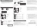
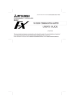
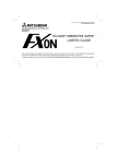
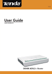
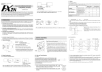
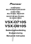
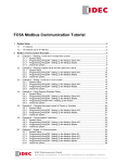
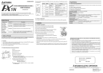
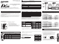
3
The control line is set by b12.
SPECIFICATION
b12 = 0 : No hardware hand shaking. Send and receive are controlled by software protocol.
3.1 General specification
b12 = 1 : Hardware hand shaking. Signal lines ER(DTR)and DR(DSR)are used to control send and receive of data.
General specifications is same as those for the FX2N series programmable controller.
When sending
3.2 Power supply specification
FX2N-232-BD COMMUNICATION BOARD
USER’S GUIDE
JY992D66001A
This manual contains text, diagrams and explanations which will guide the reader in the correct installation and
operation of the FX2N-232-BD and should be read and understood before attempting to install or use the unit.
Further information can be found in the FX SERIES PROGRAMMING MANUAL, FX2N SERIES HARDWARE MANUAL
and FX-485PC-IF USER’S MANUAL.
1
b 12
1
Pin No.
3.3 Specification
b 11
0
3
SD (TXD)
4
6
The communication board FX2N-232-BD for RS232C (hereinafter referred to as “232BD”) can be connected to the main
unit of the FX2N Series programmable controller, and used as the port for the following applications.
(1) To perform data transfer between RS232C devices such as personal computers, bar code readers and printers.
(2) To perform data transfer using the dedicated protocol between RS232C devices. For details of the dedicated
protocol, refer to the users manual of the FX-485PC-IF.
(3) To connect a programming tool.
And when the 232BD is used for the application (1) or (2) above, the communication format including the baud rate, the
parity and the data length is specified by the parameters or the contents of the special data register D8120 of the FX2N
programmable controller.
Only one 232BD can be connected to one base unit. Accordingly, the 232BD cannot be used together with the
FX2N-485-BD or the FX2N-422-BD. When two or more RS232C units are required to be connected for the application,
use the special block for RS232C communication.
1
2
3 4
39
24.99(0.98")±0.3(0.012")
54(2.13")
46(1.81")
5
4
ER (DTR)
DR (DSR)
6
DR (DSR)
9-pin D-SUB type
Pin layout of connector
1:CD(DCD) 2:RD(RXD) 3:SD(TXD) 4:ER(DTR) 5:SG(GND) 6:DR(DSR)
7,8,9:NC(No connection)
b 12
1
Pin No.
LED indicators
RXD, TXD
b 11
1
3
SD (TXD)
Communication method
Half-duplex communication system
Protocol
Programming protocol, dedicated protocol (format 1 or 4), non protocol
2
RD (RXD)
Isolation
No isolation
4
ER (DTR)
6
DR (DSR)
Diagnostic
devices
M8121
M8122
M8123
M8124
M8126
M8127
M8128
M8129
M8161
Diagnostic
devices
Data transmission delayed (RS instruction)
D8120
Data transmission flag (RS instruction)
D8121
Finished receiving data (RS instruction)
D8122
Carrier detection flag (RS instruction)
D8123
Global flag (dedicated protocol)
D8124
On demand handshake flag (dedicated protocol)
D8125
On demand error flag (dedicated protocol)
D8127
On demand Byte/Word flag (dedicated protocol)
D8128
D8129
Selection of 8 bit operations for applied instructions
ASC, RS, ASCI, HEX, CCD (RS instruction)
Operation
➁ Connector for programmable controller
Contents
0 (OFF)
1 (ON)
7 bit
8 bit
b1
b2
Parity
b2,b1
(0, 0) : None
(0, 1) : Odd
➃ TXD LED : Flashes at high speed during sending.
b3
Stop bit
➄ Connector (9-pin D-SUB type) for peripheral unit
The top face of this connector is higher than the top face of the panel
cover of the programmable controller by approximately 3 mm (0.12")
or by approximately 50 mm when the cable is connected.
b4
b5
b6
b7
b7,b6,b5,b4
(0, 0, 1, 1) : 300
Baud rate (bps) (0, 1, 0, 0) : 600
(0, 1, 0, 1) : 1,200
(0, 1, 1, 0) : 2,400
Bit
No.
Communications format (RS instruction, dedicated protocol)
Local station number (dedicated protocol)
Amount of data to be transmitted (RS instruction)
Amount of remaining data already received (RS instruction)
Data header <default STX (02H)> (RS instruction)
Data terminator <default ETX (03H)> (RS instruction)
On demand head device register (dedicated protocol)
On demand data length register (dedicated protocol)
Data network ‘time-out’ timer value (dedicated protocol)
b2,b1
(1, 1) : Even
1 bit
2 bit
b7,b6,b5,b4
(0, 1, 1, 1) : 4,800
(1, 0, 0, 0) : 9,600
(1, 0, 0, 1) : 19,200
➅ Mounting holes of connector <2 - M2.7 (0.11") × 0.635 (0.025")>
0 (OFF)
Data
Data
Data
Receive
Data
WIRING
The connector of the 232BD is 9-pin D-SUB (see Section 1.2 and Chapter 2). The connections of RS232C devices
varies with each device being used. Check the specification of the device, and connect.
4.1 Connection examples
4.1.1 Terminal specification device
RS232C device
Uses ER, DR *
Uses RS, CS
25-pin 9-pin
25-pin 9-pin
Meaning
Meaning
D-SUB D-SUB
D-SUB D-SUB
232BD
9-pin D-SUB
RD (RXD)
3
2
RD (RXD)
3
2
2
RD (RXD)
SD (TXD)
2
3
SD (TXD)
2
3
3
SD (TXD)
ER (DTR)
20
4
RS (RTS)
4
7
4
ER (DTR)
SG (GND)
7
5
SG (GND)
7
5
5
SG (GND)
DR (DSR)
6
6
CS (CTS)
5
8
6
DR (DSR)
* When using ER and DR signals, please also check if RS and CS signals are needed according to the
RS232C device's specifications.
1 (ON)
None
b9
Terminator
character *1
None
b10
Reserved
b11
DTR check
(Control line) *4
Send and receive
Receive
b12
Control line *4
None
RS232C device
Uses ER, DR *
Uses RS, CS
25-pin 9-pin
25-pin 9-pin
Meaning
Meaning
D-SUB D-SUB
D-SUB D-SUB
D8124 *2
D8125 *3
232BD
9-pin D-SUB
CD (DCD)
8
1
CD (DCD)
8
1
1
RD (RXD)
3
2
RD (RXD)
3
2
2
RD (RXD)
SD (TXD)
2
3
SD (TXD)
2
3
3
SD (TXD)
H/W
CD (DCD)
ER (DTR)
20
4
RS (RTS)
4
7
4
ER (DTR)
SG (GND)
7
5
SG (GND)
7
5
5
SG (GND)
DR (DSR)
6
6
CS (CTS)
5
8
6
DR (DSR)
b13
Sum check *5
Sum check code
is not added
Sum check code
is added
automatically
b14
Protocol
No protocol
Dedicated protocol
* When using ER and DR signals, please also check if RS and CS signals are needed according to the
RS232C device's specifications.
b15
Transmission
control protocol *5
Protocol format 1
Protocol format 4
4.1.3 When programming or monitoring
Use F2-232CAB-1 and 25-pin D-SUB to 9-pin D-SUB adapter or make a suitable cable.
*1
Set to “0" when using the dedicated protocol.
*2
Effective only when no protocol (RS instruction) is selected, and has an initial value of STX (02H: Can be modified by
the user).
1
Receive
4.1.2 Modem specification device
Contents
Meaning
Header character
*1
b8
Send
Data
To connect the 232BD to RS232C device use an RS232C cable. Make sure that the shield of cables is connected to
ground (100 Ω or less).
3.5 Communication format D8120
Meaning
Data
4
Operation
Data length
35
ER (DTR)
Connector
b0
6
RD (RXD)
Max. 15m
➀ Mounting holes <2-φ 4.0 (0.16")>
➂ RXD LED : Flashes at high speed during sending.
2
Transmission distance
Bit
No.
Dimensions : mm (inches) Accessory : M3 self-tapping screws × 2, mounting bracket × 2
Send
Conforming to RS232C
To send and receive the data between the RS232C unit using the 232BD, the communication format including the
transmission speed (baud rate) and the parity must be consistent between the 232BD and the RS232C unit.
The communication format can be set using parameters or the contents of special data register D8120 of the FX2N
programmable controller. Make sure to set appropriately the communication format in accordance with the RS232C unit
used. For the setting method using the parameters of the FX2N programmable controller, refer to the manual of the
peripheral unit used.
Make sure to turn off the power of the programmable controller and turn it on again after modifying the setting.
1.1 EXTERNAL DIMENSIONS
Pin No.
Transmission standard
3.4 Related flag and data registers
INTRODUCTION
When receiving
5 V DC, 60 mA is required from the programmable controller.
5
MOUNTING PROCEDURE
Turn off the power of the programmable controller, and mount the 232BD using the following procedure.
TERMINAL LAYOUTS
The connector is a 9-pin D-SUB type, and the pin configuration is as shown below.
Pin No.
1
6
2
7
Signal
Meaning
4
9
5
Effective only when no protocol (RS instruction) is selected, and has an initial value of ETX (03H: Can be modified by
the user).
*4
Set to (b11, b12) = (1, 0) when using the dedicated protocol.
*5
Set to “0" when using no protocol.
CD(DCD)
Carrier detection
ON when carrier is detected for data reception
3.5.1 Example program of setting
2
RD(RXD)
Receive data
Receive data (RS232C device to 232BD)
3
SD(TXD)
Send data
Send data (232BD to RS232C device)
4
ER(DTR)
Send request
Signal requesting preparation for data sending to RS232C
device
The communication format is set by special data register D8120.
Setting the communication format using D8120 is effective only at the time the
RS instruction is driven, and therefore if changed after driving, it is not actually
accepted.
5
SG(GND)
Signal ground
Signal ground
6
DR(DSR)
Send enable
Shows RS232C device is ready to receive
NC
No connection
7,8,9
➀
➁
➂
Function
1
3
8
*3
Data length
8 bit
Parity
Even
Stop bit
2 bit
An example of setting D8120 is shown below.
M8002
MOV
H138F
D8120
H138F = 0001 0011 1000 1111(binary)
The settings for the above program are as right.
Baud rate
9,600
Protocol
No protocol
Header
Used
Terminator
Used
Control line
H/W
DTR check
Send and receive
Remove the panel cover from the top face of the main unit.
Connect the 232BD to the board mounting connector provided on the base unit.
Fix the 232BD to the main unit using the M3 self-tapping screws provided,
fitting the mounting bracket and the round crimp-style terminal with the
ground cable as shown in the figure on the right.
Make sure that the crimp-style terminal is attached in the direction shown
in the figure on the right, and that the ground cable extends from the unit
shown in the figure below.
Tightening torque: 0.3 to 0.6 Nm (3 to 6 kgf⋅cm)
5.5mm(0.22") or less
2
➃
For M3(0.14")
4
1 3
Grounding
Cable
X3
X1
232BD
16mm(0.63") or less
Y0
Cut out the hole provided on the left portion of the panel cover using a tool
such as nippers and cutter so that the terminal block can be seen. The top
face of this connector is higher than the top face of the panel cover of the
programmable controller by approximately 7 mm (0.27").
2
Y2
Y1
6
CAUTION FOR USE
1)
When programming tool is connected the 232BD, do not use any other communication format or parameters. If
communication format or parameters is set, programming is not possible.
2)
Only one programming tool (such as FX-10P, FX-20P, etc.) should be connected to either the programming port or
the port provided on the 232BD. If a programming tool is connected to both connectors, the following may occur.
a)
b)
2)
Preparation of software
• Use ordinary communication software (terminal
emulator) or dedicated program in the personal
computer.
The communication format of the PC for this example
is as follows.
Receive
When the sampling trace function of the programmable controller is used from both ports, the correct sampling
trace result cannot be obtained.
232BD
• Use the communication cable suited to the connector
pin configuration of the personal computer.
(For representative wiring see section 4.)
1)
Data length
8 bit
Parity
Even
Stop bit
1 bit
Baud rate
2400
FX2N
• Send data
• Receive data
• Receive data
• Send data
PROGRAM EXAMPLES
1)
Make sure that the communication format is consistent between the external unit (RS232C unit) and the
programmable controller (D8120). If it is not consistent, correct the setting of the communication parameters or
correct the contents of the D8120. When the D8120 is modified, turn on the RS instruction again. When the
communication parameters are modified, turn off the power of the programmable controller, then turn it on again.
2)
Check the timing for sending and receiving the data. For example, confirm that the counterpart unit is ready for
receiving before sending the data.
3)
If a terminator is not used, make sure that the send data quantity is consistent with the receivable data quantity. If
both quantities are not consistent with each other, make them be consistent. (If the send data quantity varies, use
a terminator.)
4)
Make sure that the external unit is operating correctly.
5)
Make sure that the data format transferred is equivalent. If it is not equivalent, correct it.
6)
When the RS instruction is used twice or more in the program, make sure that only one RS instruction is turned on
in one calculation cycle. Never set the RS instruction to OFF state while the data is being received or sent.
Send
The program inside the programmable controller may not be consistent with the program inside the
programming tool. If the program is modified or the set value for the timer or the counter is modified, a part of
the program may be damaged and the programmable controller may malfunction.
7
8.3 When communication is performed between the computer using the no protocol
Connect 232BD and a personal computer, and exchange data with PC.
If the communication format of the soft ware cannot be
adjusted to this setting, adjust the PC and the software
to be the same.
8.4 When the dedicated protocol is used for communication between the computer
Sequence program
Connecting 232BD and a printer, and printing out the data sent from the PC.
1)
Make sure that the communication format is consistent between the computer (RS232C unit) and the programmable
controller (D8120). If it is not consistent, correct the setting of either the computer or the programmable controller.
When the programmable controller is modified, turn off the power of the programmable controller, then turn it on
again.
2)
Make sure that the station No. of the programmable controller which is the target of data transfer is equivalent to the
station No. set in the communication procedure. If they are not equivalent, correct the wrong one.
3)
Make sure that the communication procedure is correct. If it is not correct, modify the setting of the RS232 unit to
realize correct procedure.
4)
Check whether errors have occurred in the RS232 unit and the programmable controller. For the check method and
the countermeasures, refer to the users manual of the FX-485PC-IF.
5)
If the RS instruction is used in the program, delete it, turn off the power of the programmable controller, then turn it
on again.
M8000
0
M8161
Handled by 8-bit data 1
M8002
3
[MOV H0067 D8120]
Setting of communication format 2
X000
9
[RS D200 K11 D500 K0]
RS instruction drive 3
X001
Send
19
[PLS M0]
M0
22
232BD
• Receive data
[MOV H0074 D200]
Writing of send data 4
Herein, "test line" is sent.
FX2N
[MOV H000D D209]
• Send data
[MOV H000A D210]
• The communication format of the serial printer is as follows.
[SET M8122]
Send request 5
M8123
Data length
8 bit
Parity
Even
81
[MOV D500 K4Y000]
Output of receive data 6
X002
89
[PLS M1]
Receive completion reset 7
M1
Stop bit
1 bit
Baud rate
2400 bps
Sequence program
92
[RST M8123]
96
[END]
Operation
M8000
0
M8161
Handled by 8-bit data 1
Power on
M8002
3
[MOV H0067 D8120]
Setting of communication format 2
Turn on the power of the PC and printer, check the printer
is on line and switch the PC to RUN.
1
2
X000
9
[RS D200 K11 D500 K0]
RS instruction drive 3
X000, ON
X001
19
[PLS M0]
M0
22
RS instruction drive
[MOV H0074 D200]
Turn on X000, and drive RS instruction.
3
[MOV H0065 D201]
[MOV H006E D207]
X001, ON
Writing of send data 4
Herein, "test line" is sent.
Data send
[MOV H0065 D208]
[MOV H000A D210]
[SET M8122]
Send request 5
Data send
[END]
Operation
Power on
Turn on the power of the PC
and printer, check the printer
is on line and switch the PC to
RUN.
1
2
• In this example, CR (H000D) and LF
(H000A) are written at the end of the
message. The printer moves down one
line for each message.
5
Turn on X000, and drive RS
instruction.
Every time X001 is turned on,
the contents of D200 to D210
are sent to the printer, and
"test line" is printed.
• Under no circumstances will Mitsubishi Electric be liable or responsible for any consequential
damage that may arise as a result of the installation or use of this equipment.
• All examples and diagrams shown in this manual are intended only as an aid to understanding
the text, not to guarantee operation. Mitsubishi Electric will accept no responsibility for actual
use of the product based on these illustrative examples.
• Owing to the very great variety in possible application of this equipment, you must satisfy yourself
as to its suitability for your specific application.
DIAGNOSTICS
: JY992D66001
1)
Manual revision
:A
Date
: JUNE 1997
Make sure that the programmable controller is connected and that the POWER LED is lighted on the programmable
controller.
2)
Make sure that the VRRD or VRSC instruction is not used in the program. If such an instruction is used, delete it,
turn off the power of the programmable controller, then turn it on again.
3)
When the special auxiliary relay M8070 or M8071 is turned on, turn off the relay using the peripheral unit, turn off the
power of the programmable controller, then turn on the power again.
4)
Make sure that wiring is performed correctly. Refer to Section 4.
5)
Make sure using the peripheral unit that the communication parameters are set correctly in accordance with the
application. If the setting is not correct, set the parameters correctly using the peripheral unit.
HEAD OFFICE:MITSUBISHI DENKI BLDG MARUNOUCHI TOKYO 100 TELEX:J24532 CABLE MELCO TOKYO
HIMEJI WORKS:840, CHIYODA CHO, HIMEJI, JAPAN
8.2 When the parallel link function is used
4
5
7
• If in doubt at any stage during the installation of the FX2N-232-BD always consult a professional
electrical engineer who is qualified and trained to the local and national standards. If in doubt
about the operation or use of the FX2N-232-BD please consult the nearest Mitsubishi Electric
distributor.
Manual number
3
X001, ON
6
• This manual has been written to be used by trained and competent personnel. This is defined by
the European directives for machinery, low voltage and EMC.
8.1 Common items
CR : Carriage Return
LF : Line Feed
Data send
After receiving and storing data from personal computer in
D500, it is output to Y000 to Y017. When input X002 is
turned on, the receive completion flag is reset.
8
X000, ON
RS instruction drive
4
Personal
computer
operation
[MOV H000D D209]
80
Every time X001 is turned on, the contents of D200 to
D210 are sent to the personal computer, and "test data" is
displayed.
Guidelines for the safety of the user and protection of the FX2N-232-BD
Note: It may be necessary to set the DIP
switches of your printer.
Check your printer manual for how
to configure the serial
communications.
1)
Make sure that the communication format is in the initial state (D8120 = K0). Check using the peripheral unit how the
communication parameters are set. If the no protocol (RS instruction) or the dedicated protocol is selected, set
the parameters correctly using the peripheral unit.
2)
If the RS instruction is used in the program, delete it, turn off the power of the programmable controller, then turn it
on again.
JY992D66001A
Effective JUN. 1997
Specifications are subject to
change without notice