1
HARDWARE MANUAL
FX2N-32CAN Communication Module
FX2N-32CAN Communication Module
Foreword
• This manual contains text, diagrams and explanations which will guide the reader in the correct installation
and operation of the communication facilities of the FX2N-32CAN module.
• Before attempting to install or use the communication facilities of the FX2N-32CAN module, this manual and
FX2N-32CAB User’s Manual should be read and understood.
• If in doubt at any stage of the installation of the communication facilities of the FX2N-32CAN module always
consult a professional electrical engineer who is qualified and trained to the local and national standards
which apply to the installation site.
• If in doubt about the operation or use of the communication facilities of the FX2N-32CAN module please
consult the nearest Mitsubishi Electric distributor.
• This manual is subject to change without notice.
FX2N-32CAN Communication Module
FX2N-32CAN Communication Module
Manual number : JY992D92901
Hardware Manual
Manual revision : C
Date
: May 2006
This manual confers no industrial property rights or any rights of any other kind, nor does it confer any patent
licenses. Mitsubishi Electric Corporation cannot be held responsible for any problems involving industrial
property rights which may occur as a result of using the contents noted in this manual.
i
FX2N-32CAN Communication Module
Guidelines for the safety of the user and protection of the FX2N-32CAN
Communication Module.
This manual provides information for the use of the FX2N-32CAN Communication Module. The
manual has been written to be used by trained and competent personnel. The definition of
such a person or persons is as follows:
a) Any engineer who is responsible for the planning, design and construction of automatic
equipment using the product associated with this manual should be of a competent
nature, trained and qualified to the local and national standards required to fulfill that
role. These engineers should be fully aware of all aspects of safety with regards to
automated equipment.
b) Any commissioning or service engineer must be of a competent nature, trained and
qualified to the local and national standards required to fulfill that job. These engineers
should also be trained in the use and maintenance of the completed product. This
includes being completely familiar with all associated documentation for said product. All
maintenance should be carried out in accordance with established safety practices.
c) All operators of the completed equipment (See Note) should be trained to use that
product in a safe manner in compliance to established safety practices. The operators
should also be familiar with documentation which is connected with the actual operation
of the completed equipment.
Note : The term ‘completed equipment’ refers to a third party constructed device which
contains or uses the product associated with this manual.
ii
FX2N-32CAN Communication Module
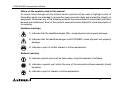
Note’s on the symbols used in this manual
At various times through out this manual certain symbols will be used to highlight points of
information which are intended to ensure the users personal safety and protect the integrity of
equipment. Whenever any of the following symbols are encountered its associated note must
be read and understood. Each of the symbols used will now be listed with a brief description of
its meaning.
Hardware warnings
1) Indicates that the identified danger WILL cause physical and property damage.
2) Indicates that the identified danger could POSSIBLY cause physical and property
damage.
3) Indicates a point of further interest or further explanation.
Software warning
4) Indicates special care must be taken when using this element of software.
5) Indicates a special point which the user of the associate software element should
be aware.
6) Indicates a point of interest or further explanation.
iii
FX2N-32CAN Communication Module
• Under no circumstances will Mitsubishi Electric be liable responsible for any consequential
damage that may arise as a result of the installation or use of this equipment.
• All examples and diagrams shown in this manual are intended only as an aid to
understanding the text, not to guarantee operation. Mitsubishi Electric will accept no
responsibility for actual use of the product based on these illustrative examples.
• Please contact a Mitsubishi Electric distributor for more information concerning applications
in life criticatical situations or high reliability.
iv
FX2N-32CAN Communication Module
Note Concerning the CE Marking
This document does not guarantee that a mechanical system including this product will comply
with the following standards. Compliance to EMC standards of the entire mechanical system
should be checked by the user / manufacturer. Compliance to LVD standards of the entire
mechanical system should be checked by the user / manufacturer.
EMC
The following products have shown compliance through direct testing (of the identified
standards below) and design analysis (through the creation of a technical construction file) to
the European Directive for Electromagnetic Compatibility (89/336/EEC) when used as directed
by the appropriate documentation. Refer to a manual or related material of each product other
than the following.
v
FX2N-32CAN Communication Module
Type :
Programmable Controller (Open Type Equipment)
Models : FX2N-32CAN manufactured
from November 1st, 2001 to April 30th, 2006 are
compliant with EN50081-2 and EN61131-2:1994+A11:1996
after May 1st, 2006 are compliant with EN61131-2:2003
Standard
Remark
EN50081-2:1993 Electromagnetic compatibility
Compliance with all relevant aspects of the standard.
- Generic emission standard
(Radiated Emissions)
Industrial environment
EN61131-2:1994 Programmable controllers
/A11:1996 - Equipment requirements
and tests
Compliance with all relevant aspects of the standard.
(RF Immunity, Fast Transients , ESD and Damped
oscillatory wave)
EN61131-2:2003 Programmable controllers
- Equipment requirements
and tests
Compliance with all relevant aspects of the standard.
(Radiated Emissions, Mains Terminal Voltage
Emissions, RF immunity, Fast Transients, ESD,
Surge, Voltage drops and interruptions, Conducted
and Power magnetic fields)
For more details, please contact the local Mitsubishi Electric sales site.
- Note for using the FX2N-32CAN
For complicance to EC EMC directive, install the FX2N main unit, extension unit/block and
the FX2N-32CAN in a shielded metal cabinet.
vi
FX2N-32CAN Communication Module
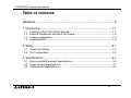
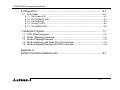
Table of contents
Guideline ............................................................................................. iii
1. Introduction............................................................................................1-1
1.1
1.2
1.3
1.4
Features of the FX2N-32CAN Module.................................................................. 1-1
External Dimensions and Each Part Name ......................................................... 1-2
System configuration ........................................................................................... 1-4
Applicable PLC .................................................................................................... 1-4
2. Wiring ....................................................................................................2-1
2.1 Caution for Wiring................................................................................................ 2-1
2.3 Pin Configuration ................................................................................................. 2-2
3. Specifications ........................................................................................3-1
3.1 Environmental/Standards Specifications ............................................................. 3-1
3.2 Power Supply Specifications ............................................................................... 3-1
3.3 Performance Specifications ................................................................................. 3-2
vii
FX2N-32CAN Communication Module
4. Buffer Memory Structure .......................................................................4-1
4.1 Basic Buffer Memory Structure, BFM #0 ~ BFM #31 .......................................... 4-1
4.2 Buffer Memory Functions .................................................................................... 4-2
4.2.1
4.2.2
4.2.3
4.2.4
4.2.5
4.2.6
4.2.7
4.2.8
Data Transfer Locations, BFMs #0~#19 and #100~#199 ......................................... 4-2
The Data Exchange Mode, BFM #20 ........................................................................ 4-2
Setting the Baud Rate, BFM #24............................................................................... 4-3
Reading the Communication Status, BFM #25 ......................................................... 4-4
The Watch Dog Timer Setting, BFM #26 .................................................................. 4-5
The Node Address, BFM #27 .................................................................................... 4-5
Error Staus, BFM #29................................................................................................ 4-6
BFM Data Memory Backup ....................................................................................... 4-7
4.3 Extended BFM Structure, BFM #32 ~ BFM #32767 ............................................ 4-8
5. Module Parameterization and Configuration .........................................5-1
5.1 Factory Default Mapping/Mode 0 Mapping.......................................................... 5-3
5.2 Mode A Mapping ................................................................................................. 5-4
5.3 Mode B Mapping ................................................................................................. 5-5
5.3.1 Prepare the PDO Mapping Table .............................................................................. 5-6
5.4 PDO Mapping Table Overviews .......................................................................... 5-8
5.4.1 Tx-PDO Mapping Table............................................................................................. 5-8
5.4.2 Rx-PDO Mapping Table .......................................................................................... 5-10
viii
FX2N-32CAN Communication Module
6. Diagnostics............................................................................................6-1
6.1 LED Status .......................................................................................................... 6-1
6.1.1
6.1.2
6.1.3
6.1.4
6.1.5
The Power LED ......................................................................................................... 6-1
The FROM/TO LED................................................................................................... 6-1
The RUN LED ........................................................................................................... 6-2
The Rx/Tx LED .......................................................................................................... 6-2
The ERROR LED ...................................................................................................... 6-3
7. Example Program..................................................................................7-1
7.1
7.2
7.3
7.4
7.5
SDO Write Command .......................................................................................... 7-2
Mode 0 Mapping Command ................................................................................ 7-4
Mode A Mapping Example .................................................................................. 7-5
Mode A Mapping with Node Start Up Command................................................. 7-6
Mode B Mapping Example with SDO Command................................................. 7-8
Appendix A:
Further Information Manual Lists.............................................................. A-1
ix
FX2N-32CAN Communication Module
x
FX2N-32CAN Communication Module
1.
Introduction 1.
Introduction
The FX2N-32CAN Communication Module is an interface block which connects the FX2N(C)/FX1N PLC
to an existing CANopen network. The CANopen network is an internationally accepted network for
industrial automation.
For more information on the CANopen specifications please see the Can in Automation
website at www.can-cia.de.
1.1
Features of the FX2N-32CAN Module
•
•
•
•
A maximum of 120 words can be sent and received as Process Data Object (PDO) data. The number of words can be transmitted in each direction is set from 1 ~ 120.
The buffer memory of the FX2N-CANopen Communication Module is read and written by FROM/TO
instructions.
Eight I/O points from the PLC expansion port are occupied in the PLC.
The node address can be numbered from 1 to 127. A total of 30 nodes can be connected to any
segment of the bus and by the use of repeaters or bridges, the total number can be extended up to
127 nodes.
1-1
FX2N-32CAN Communication Module
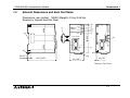
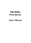
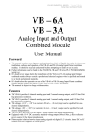
External Dimensions and Each Part Name
Dimensions: mm (inches) MASS (Weight): 0.2 kg (0.44 lbs)
Accessory: Special block No. label
a )
P O W E R
F X
2 N
-3 2 C A N
-3 2 C A N
T x /R x
E R R O R
2 N
c )
F X
e )
f)
g )
h )
i)
R U N
F R O M /T O
9 0 (3 .5 4 ")
1.2
Introduction 1.
k )
j)
b )
d )
9 (0 .3 5 ")
8 8 .7 (3 .4 9 ")
b )
4 3 (1 .6 9 ")
4 (0 .1 6 ")
R e m o v e T o p C o v e r
1-2
FX2N-32CAN Communication Module
Introduction 1.
a) Groove for DIN rail mounting (Width of DIN rail: 35 mm <1.38">)
b) Hook for Din rail
c) Extension cable
d) Direct mounting holes (2-∅4.5 mm <0.18">)
e) RUN LED: Lights when the FX2N-32CAN Communication Module is in Run mode.
f) FROM/TO: Lights when FROM/TO access is performed by the FX2N(C)/FX1N PLC to the
CANopen module.
g) Tx/Rx: Lights up when the module is exchanging data.
h) Error: Lights when a general error has occured.
i) POWER: Lights when 5 Volt power is supplied from the Programmable Controller.
j) 9 Pin D-sub Connector
k) Extension connector
1-3
FX2N-32CAN Communication Module
1.3
Introduction 1.
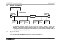
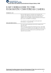
System configuration
Network
Configuration Manager
CANopen Network
Terminating
Resistor 120Ω
Terminating
Resistor 120Ω
Repeater
CANopen
Node
FX1N/FX2N
/FX2NC
FX2N32CAN
FX1N/FX2N
/FX2NC
FX2N32CAN
CANopen
Node
*1 The Maximum extension distance for the FX2N-32CAN module is 5000m at 10kbps (with
repeaters). The extension distance is reduced to 40m (130') at the maximum baud rate of 1 Mbd.
The maximum distance also depends on the specification of other connected CANopen nodes as
well as the connectors and cables used.
1.4
Applicable PLC
FX2N-32CAN can be connected to the FX2N(C) or the FX1N Series PLC.
1-4
FX2N-32CAN Communication Module
2.
Wiring
2.1
Caution for Wiring
Wiring 2.
1) Do not lay signal cable near high voltage power cables or put them in the same trunking
duct. Otherwise, the effects of noise or surge induction are likely to take place. Keep a safe
distance of more than 100 mm (3.94") from these wires.
2) The terminal tightening torque is 0.5 to 0.8 N·m (5 to 8 kgf·cm). Tighten securely to avoid
malfunction.
3) Cut off all phases of power source externally before installation or wiring work in order to
avoid electric shock or damage to the product.
2.2
Cable
The cable should conform to ISO11898/1993.
The recommended cable is a shielded 2 x 2 twisted pair cable with an impedance of about 120
Ohm. (Example: UNITRONIC BUS LD 2 x 2 x 0.22 from company Lapp Kabel,
www.lappkabel.de).
The bus line should be terminated on both ends by connectors that contain 120 Ohm
termination resistors. Recommended is a connector which was designed to be used with
CANopen networks (Example: ERbic series from company ERNI, www.erni.com) but a normal
9 pin D-Sub female connector can be used.
2-1
FX2N-32CAN Communication Module
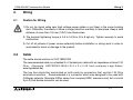
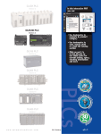
Pin Configuration
The module connector below is a 9-pin D-SUB (#4-40 inc. inch screw thread) type.
Signal
Meaning
2
Can_L
Can_L bus line, dominant low
3
Can_G
Can_Ground
7
Can_H
Can_H bus line, dominant high
A ssigned
N ot ass igned
1,4,5,6,8,9 NC
Pin not Assigned
4
8
3
7
2
6
1
Pin No.
5
9
2.3
Wiring 2.
2-2
FX2N-32CAN Communication Module
Specifications 3.
3.
Specifications
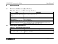
3.1
Environmental/Standards Specifications
Table 3.1: Environmental/Standards Specifications
Item
3.2
Description
Environmental specifications
excluding dielectric withstand
voltage
Same as those of the main unit.
Dielectric Withstand Voltage
500 V AC > 1 min, tested between signal line and ground
CAN Standard
ISO 11898/1993
CANopen Standard by CiA
DS-301 Version 3.0
Additional CANopen Features
NMT, Guarding, and Guarding request based on DS-302 V2.0.
Network Variables based on DS-405 V1.0
Power Supply Specifications
Table 3.2: Power Supply Specifications
Item
Description
External Power Supply
None
Internal Current Consumption
130 mA at 5 V DC
3-1
FX2N-32CAN Communication Module
3.3
Specifications 3.
Performance Specifications
Table 3.3: Performance Specifications
Item
Description
Maximum FX2N-32CAN
Modules that can be
connected to the CANopen
network.
The node address can be set from 1 ~ 127. A total of 30 nodes can be
connected on each bus. By the use of repeaters or bridges, the total
number can be extended up to 127 nodes.
Supported Baud Rate
10 kbps, 20 kbps, 50 kbps, 125 kbps, 250 kbps, 500 kbps,
800 kbps, 1 Mbps
Number of Occupied I/O
Points
8 points taken from either the input or output PLC I/O extension bus
Applicable Programmable
Controller
FX2N(c), FX1N
Communication with
Programmable Controller
FROM/TO instruction
RUN
Lit green when module is exchanging information with the CANopen
network
FROM/TO Lit green when module is receiving FROM/TO commands.
LED Indication
Tx/Rx
Lit green when CAN-interface system is in normal operation.
ERROR
Lit red when communication, overflow, or general error occurs.
POWER
Lit green when the 5 V DC power supplied from main unit.
3-2
FX2N-32CAN Communication Module
4.
Buffer Memory Structure
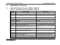
4.1
Basic Buffer Memory Structure, BFM #0 ~ BFM #31
Buffer Memory Structure 4.
Table 4.1: Buffer Memory Structure, BFM #0 - BFM #31
BFM #
BFM #0
BFM #1
:
:
BFM #19
BFM #20
BFM #21
BFM #22
BFM #23
BFM #24
BFM #25
BFM #26
BFM #27
BFM #28
BFM #29
BFM #30
BFM #31
READ (FROM)
Received data (Section 4.2.1-2)
Received data (Section 4.2.1-2)
:
:
Received data (Section 4.2.1-2)
Data exchange status bit (Section 4.2.2)
Reserved
Reserved
Reserved
Read baud rate (Section 4.2.3)
WRITE (TO)
Data to Transmit (Section 4.2.1-2)
Data to Transmit (Section 4.2.1-2)
:
:
Data to Transmit (Section 4.2.1-2)
Data exchange control bit (Section 4.2.2)
Reserved
Reserved
Reserved
Set baud rate (Section 4.2.3, default 10kBd)
Reset + CANopen restart command (Section
Module communication status (Section 4.2.4)
4.2.4)
Read FROM/TO watchdog timer reload value, Set FROM/TO watchdog timer reload value,
“default = 20” equals 200ms. (Section 4.2.5)
“default = 20” equals 200ms. (Section 4.2.5)
Set node address, default = 127. (Section
Read node address (Section 4.2.6)
4.2.6)
Reserved
Reserved
Error status (Section 4.2.7)
Reset latched error status (Section 4.2.7)
Module code (K7100)
(Read only)
Reserved
Reserved
4-1
FX2N-32CAN Communication Module
4.2
Buffer Memory Functions
4.2.1
Data Transfer Locations, BFMs #0~#19 and #100~#199
Buffer Memory Structure 4.
These Buffer memory locations in the FX 2N-32CAN module are used to receive from and
transfer data to the CANbus. The mapping for where each data is sent/received is explained
in Chapter 5.
4.2.2
The Data Exchange Mode, BFM #20
On read access, BFM #20 contains a status bit for data exchange. If bit0 is “1”, the module is in
data exchange mode and the received data are valid (no CAN error occurred). If bit0 is “0”, the
module is not in data exchange mode.
On write access, BFM #20 acts as the data exchange control signal. To ensure that the FX2N32CAN module can handle the PDO data in a consistent way, it is absolutely necessary to
write a “1” to this BFM before reading Rx PDO data (FROM) and after writing Tx-PDO data
(TO) to the module. The data exchange control signal ensures, by internal buffer exchange,
that TO data from the PLC will be transmitted within the same corresponding Tx-PDO at the
same time.
TO data will only be sent to the CAN bus after a write access to BFM #20 (data = 1).
As long as the reading of the previous data is not finished and a new exchange command to
BFM #20 has not been sent, FROM data from the CAN bus will not be (partially) overwritten by
further Rx PDOs with the same ID.
If the CAN open module is in data exchange mode, the received PDO data (Rx-PDO) from
other nodes can be read by the FX 2N(C)/FX 1N PLC by using a FROM instruction and the
transmit PDO data (Tx-PDO) can be written to the module and sent to the network by using a
TO instruction.
4-2
FX2N-32CAN Communication Module
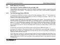
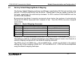
4.2.3
Buffer Memory Structure 4.
Setting the Baud Rate, BFM #24
BFM24 shows the current baud rate of the CANopen network, see the Table below. The baud
rate can be set by writing TO BFM #24. The baud rate must be equal for all nodes on the
CANopen network.
Table 4.2: Baud Rate Settings
Baud Rate
BFM #24 Value
10 kbps
10
20 kbps
20
50 kbps
50
125 kbps
125
250 kbps
250
500 kbps
500
800 kbps
800
1000 kbps
1000
4-3
FX2N-32CAN Communication Module
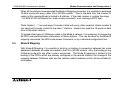
4.2.4
Buffer Memory Structure 4.
Reading the Communication Status, BFM #25
Read the CANopen module’s communication status from BFM #25 per the table below.
Table 4.3: Communication Status
Bit
On
b0: module online/offline
Off
module online
module offline
b1 ~ b7: reserved
b9, b8: CANopen network state
00b = Prepared State
01b = Pre-operational State
10b = Operational State
11b = Not Possible
b10 ~ b15: reserved
Note: On write access, BFM #25 contains the command flags to reset the FX2N-32CAN and to
restart the CAN open stack.
Table 4.4: CANopen Stack Reset
Bit
b0: restart command
On
CANopen stack will be restarted
Off
Normal operation
b1 ~ b15: reserved
The restart command can be used after the baud rate (BFM #24) or the node address (BFM
#27) was changed. By setting B0 to “1” (use the pulse instruction), the module can be forced
to go offline and to restart with the new settings without switching off the power of the host
PLC.
4-4
FX2N-32CAN Communication Module
4.2.5
Buffer Memory Structure 4.
The Watch Dog Timer Setting, BFM #26
The Watch Dog Timer setting is stored in BFM #26 in units of 10 ms. A WDT error will occur if
there is no FROM or TO instruction to any BFM for the time specified. After the WDT has
expired, it must be reset by writing the current or a new value to BFM #26. When the value 0
is written to BFM #26, the FROM/TO watchdog timer is disabled.
During normal operation as soon as the module receives a FROM or TO instruction, the WDT
will reset to time zero.
Note: No Emergency Message will be transmitted if the WDT is disabled and the FROM/TO
communication stops and the FX2N-32CAN module is in operational mode.
4.2.6
The Node Address, BFM #27
The CANopen node supports setting of the node address by the FX2N(C)/FX1N PLC via the TO
instruction. The actual address is displayed in BFM #27. The Node address must be set for
communication to take place via the CANopen bus.
In case of an address change by TO instruction, the new address value (1...127d) must be
written to BFM #27. The new address will only become effective after a power down of the
host PLC or after a restart command written to BFM #25.
4-5
FX2N-32CAN Communication Module
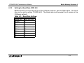
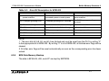
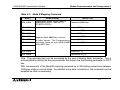
4.2.7
Buffer Memory Structure 4.
Error Staus, BFM #29
BFM #29 reflects the error status of the module. Bit 7 shows the status of the FROM/TO
watchdog timer (see section 4.1.7, BFM #26). In case of a watchdog timer error (b7 is ON) an
external emergency message will be sent to the CANopen network if the module is in
operational mode.
When the value 0 is written to BFM #26, the FROM/TO watchdog timer is disabled and b7 of
BFM #29 will never become “1”.
Table 4.5: Error Bit Description for BFM #29
Bit
b0: general error
On
Off
This bit is ON if b2, b3 or b4 are On
No general error
b2: power error
Power supply error
Power supply normal
b3: CAN bus off error
CAN bus off error
b4:EEPROM/flash memory error
Data in EEPROM or flash memory is EEPROM and flash memory data
corrupted
normal
b1: reserved
b5, b6: reserved
b7: FROM/TO watchdog timer
No FROM/TO instruction received FROM/TO instructions received
(reset by writing a value to BFM (for the time specified in BFM #26) regularly
#26)
b8: Data queue overflow
Data could not be written to internal
No data queue overflow
queue
4-6
FX2N-32CAN Communication Module
Buffer Memory Structure 4.
Table 4.5: Error Bit Description for BFM #29
Bit
On
Off
b9: Command queue or event Data could not be written to internal N o c o m m a n d q u e u e o r eve n t
queue overflow
command queue or event queue
queue overflow
b10: CANopen guarding error
CANopen guarding error occurred
No CANopen guarding error
occurred
b11: Baud rate change error
New baud rate not valid, no change
Set baud rate valid
b12: Address change error
New address not valid, no change
Address is valid
b13: CANopen emergency
CANopen emergency occurred
No emergency exists
b14: CAN error passive state
CAN error passive
CAN error active
b15: Reserved
NOTE:
1. The error bits b2, b8, b9, and b14 are latched and must be reset from the PLC by writing “0”
to the appropriate bit in BFM #29. By writing “0” to all of BFM #29, all latched error flags will be
cleared.
2. All other error flags will be reset automatically as soon as the corresponding error has been
solved.
4.2.8
BFM Data Memory Backup
The data in BFM #24, #26, and #27 are kept by EEPROM.
4-7
FX2N-32CAN Communication Module
4.3
Buffer Memory Structure 4.
Extended BFM Structure, BFM #32 ~ BFM #32767
Table 4.6: Extended BFM Structure
BFM #
READ (FROM)
WRITE (TO)
BFM #32 ~ #99
Reserved
Reserved
BFM #100 ~ #199
Received Output Data
Transmit Data
BFM #200 ~ #999
Reserved
Reserved
BFM #1000 ~ #1066
Module Command Interface
Module Command Interface
BFM #1067 ~ #32767
Reserved
Reserved
The module command interface offers the possibility to send commands directly to the
CANopen module. This command interface can be used to manipulate and control all items in
the object dictionary, to send and receive SDO messages, to send network management
messages, or to send emergency messages.
Please see the FX2N-32CAN User’s Manual for more information.
4-8
FX2N-32CAN Communication Module
5.
Module Parameterization and Configuration 5.
Module Parameterization and Configuration
Each CANOpen node must have certain parameters defined in order to communicate
information to other CANOpen nodes. These parameters include the Node Number, the baud
rate, the Watch Dog Timer setting (specific for FX2N-32CAN module), and the communication
mapping set.
The CANopen network has a defined Object Dictionar y for parameters and data
communication. The FX2N(C)/FX1N PLC can write this information to the CANbus through the
buffer memory addresses of the FX2N-32CAN module.
A network configuration tool is a powerful device for setting the parameter data for any
manufacturers node (including the FX2N-32CAN) and defining the data mapping connection
set. It is recommended to use a network configuration tool for large networks due to the
convenience, flexibility, and ease of use that the tools provide.
To build up a small network or for testing purposes, the module Command InterFace (hereafter
called the CIF) supports three PDO mapping/binding commands designed for and supported
by the FX2N-32CAN module. Example PLC programs are given in Chapter 7. By using these
predefined Mapping configurations, the CAN object ID (COB-ID) number for data exchange for
each node is clearly defined. For example an Rx-PDO (receive process data object) can be
connected to a Tx-PDO (transmit process data object) of another node. These data will
always be transmitted with the same COB-ID and every node can distinguish relevant data by
checking the COB-ID.
Note: It is strongly recommended to execute the Mapping Commands only in the preoperational or stopped mode of the local and all related CANopen nodes.
5-1
FX2N-32CAN Communication Module
Module Parameterization and Configuration 5.
Vocabulary Terms
Rx-PDO - Receive Process Data Objects are data read from other nodes via the CAN bus.
Tx-PDO - Transmit Process Data Objects are the data sent to other nodes via the CAN bus.
CIF - The Command Interface is the FX2N-32CAN tool used to perform actions such as to set
parameters, execute commands, establish communication connections, access the CANopen
Object Dictionary, and read error messages. It is located in BFM #1000~#1066.
COB-ID - The CAN Object ID number is a unique identifying number to distinguish between
different messages on the CANBus (e.g. PDO, SDO,NMT,SYNC, EMCY messages)
BFM - The Buffer Memory is the data storage memory location.
Mapping Mode 0 - Base Configuration where 4 Rx-PDOs and 4 Tx-PDOs are given BFM
assignments for each FX 2N -32CAN node according to the pre-defined connection set of
CANopen.
Mapping Mode A - Mitsubishi Electric defined configuration for the FX2N-32CAN module that
defines the relationship between up to eight FX2N-32CAN nodes, the node BFMs, and the RxPDOs and Tx-PDOs. This mode is very convenient if every node is an FX2N-32CAN module.
Mapping Mode B - Configuration mode that allows specific Rx-PDOs and Tx-PDOs to be
matched on a node by node basis.
For more detailed information on all the features and capabilities of the FX2N-32CAN module
please refer to the FX2N-32CAN User’s Manual.
For more information on the CANopen specifications please see the Can-in-Automation
website at www.can-cia.de.
5-2
FX2N-32CAN Communication Module
5.1
Module Parameterization and Configuration 5.
Factory Default Mapping/Mode 0 Mapping
The Factory Default Mapping conforms to CANopen specification DS-301 and contains only
the first 2 Tx-PDOs and the first two Rx-PDOs. Please refer to the two Tables in section 5.4
that give, repectively, the relationships between Tx-PDO number/COB-IDs/BFM# and the
Rx-PDO/COB-IDs/BFM#.
By executing the Mode 0 mapping command shown below the number of automatically
assigned Tx-PDOs becomes four instead of two. Four Rx-PDOs are also mapped
automatically.
Table 5.1:
Mode 0 Mapping Command
BFM #
READ (FROM)
WRITE (TO)
BFM #1000
Mapping successfully established (8901)
Command (8900 hex)
BFM #1001
Unused
Unused
:
Unused
Unused
BFM #1066
Unused
Unused
The BFM #0 - #15 are distributed to Rx-PDOs 1-4 and Tx-PDOs 1-4 as shown in section 5.4.
This setting is useful for a network that features many different types of node or as a base for a
network mapping configured with the Mode B mapping command.
The PDOs from 5-30 (BFM #16 ~ #19 and BFM #100 ~ #199) are disabled in the default
settings but further mapping of BFM #16 ~ #19 and BFM #100 ~ #199 can be accomplished
using the Mode B mapping technique.
5-3
FX2N-32CAN Communication Module
5.2
Module Parameterization and Configuration 5.
Mode A Mapping
Setting up a CANopen network of only FX2N-32CAN nodes can be accomplished by simply
using the Mode A Mapping configuration. Other types of CANopen modules can be added to
the Network but additional user inputs are necessary.
Table 5.2: Mode A Mapping Command
BFM #
READ (FROM)
WRITE (TO)
BFM #1000
Mapping successfully established (8201 hex).
Command (8200 hex)
Local node number MUST be in the range 1 - 8 (82FF hex)
BFM #1001
Unused
Unused
:
Unused
Unused
BFM #1066
Unused
Unused
To establish communication between a FX2N-32CAN node and up to 7 other FX2N-32CAN
nodes it is only necessary to write the “set Mode A Mapping” command (8200 hex) via the
local PLC of every FX 2N -32CAN. One of the nodes must be configured as the network
manager. The network manager can be defined in the Network Configuration tool or by writing
to the Object Dictionary using the CIF SDO write command. See Chapter 7 for example
programs.
5-4
FX2N-32CAN Communication Module
Module Parameterization and Configuration 5.
When all the stations have executed the Mode A Mapping command, it is possible to exchange
16 data words with every other FX2N-32CAN module*. Due to the data size, the number of
nodes in this mapping Mode is limited to 8 stations. If the node number is outside the range
1-8, BFM #1000 will display the “node number mismatch” error message (82FF hex).
*Note: Nodes 1 - 7 can exchange 16 words of data with every other node but station number 8
can send just 8 words of data to the other 7 stations. Node 8 can read the 16 words of data
from all the other stations.
To include other types of CANopen nodes in the Mode A network, it is necessary to change the
Rx-PDO and communication parameters of these stations. This can be done by the Mode B
mapping commands, the SDO write access Command, or by a standard configuration tool.
5.3
Mode B Mapping
With Mode B Mapping, it is possible to build up a binding (a connection between two node
addresses) between all nodes connected to the FX2N-32CAN module. Also, the binding of any
CANopen node with any other node is supported. The Mode B mapping is limited to the
binding of the PDOs which are already configured in the remote stations (no change of the
mapping between CANopen data and the remote node’s hardware) which will be suitable for
most cases.
5-5
FX2N-32CAN Communication Module
5.3.1
Module Parameterization and Configuration 5.
Prepare the PDO Mapping Table
The Mode B mapping command will modify or add to the current PDO mapping, therefore it is
important to have a clearly defined mapping base before executing any Mode B commands.
Executing the Mode B Mapping commands before creating a PDO mapping base may create
errors in the data transmission or module operation.
The PDO mapping base can be the “Mode 0” mapping or the “Mode A” mapping explained in
previous sections to prepare the default Rx-PDO and Tx-PDO formats as shown in section 5.4.
Another method to create (or reset) a Mapping base is to initialize the Mode B Mapping with a
special instruction at the beginning of the Mode B Mapping Command.
The purpose of the Mode B Mapping Commands is to bind a Tx-PDO from one CANopen node
to a Rx-PDO of another node. This allows certain Buffer Memory information to be transfered/
read in designated nodes around the CANopen network.
The Source parameter specifies the Node number and the specific Tx-PDO. The Destination
parameter specifies the Node number and the specific Rx-PDO that can read the data. The
command consists of four hexadecimal numbers, the two higher byte numbers specify the
node number and the two lower numbers specify the appropriate PDO number.
5-6
FX2N-32CAN Communication Module
Module Parameterization and Configuration 5.
Table 5.3: Mode B Mapping Command
BFM #
BFM #1000
READ (FROM)
Binding done without errors - 8301 H.
Binding error occurs - Hex 83FF H.
CIF BUSY (FFFFh)
WRITE (TO)
Command (8300 hex)
BFM #1001
Source 1 [*1]
BFM #1002
Destination 1 [*2]
BFM #1003
Source 2 [*1]
BFM #1004
Diagnosis Data: 0000 hex = no error
BFM #1005
Source 3 [*1]
All other Values: The Corresponding
parameter cause an error (BFM #1000 Destination 3 [*2]
will be 83FF hex)
BFM #1006
:
:
Destination 2 [*2]
BFM #1065
Source 33 [*1]
BFM #1066
Destination 33 [*2]
:
:
Note: The parameter set must be terminated by the “end of binding Table” parameter. This is
accomplished by setting the Source parameter that follows the final binding parameter to FFFF
hex.
With one execution of the Mode B mapping command up to 33 binding connections between
CANopen stations can be made. To establish more data connections, the command can be
repeated as often as necessary.
5-7
FX2N-32CAN Communication Module
Module Parameterization and Configuration 5.
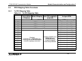
5.4
PDO Mapping Table Overviews
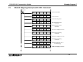
5.4.1
Tx-PDO Mapping Table
Table 5.4: Tx-PDO Mapping Table
Default
Factory/Mode
0 Mapping*
Mode B Mapping
Mode A Mapping (after PDO mapping is
prepared)
Assigned BFM
COB ID
Mapped BFMs (access style)
Tx-PDO 1
0180 hex + node ID
BFM #3 ... BFM #0 (TO)
Tx-PDO 2
0280 hex + node ID
BFM #7 ... BFM #4 (TO)
Tx-PDO 3
0380 hex + node ID
BFM #11 ... BFM #8 (TO)
Tx-PDO 4
0480 hex + node ID
BFM #15 ... BFM #12 (TO)
Tx-PDO 5
BFM #19 ... BFM #16 (TO)
Tx-PDO 6
BFM #103 ... BFM #100 (TO)
Tx-PDO 7
BFM #107 ... BFM #104 (TO)
Tx-PDO 8
Tx-PDO 9
Tx-PDO 10
Tx-PDO 11
Disabled
(COB-ID set to 80000000 hex).
These PDOs can be activated by
mode B mapping commands.
Disabled (COB-ID set to
80000000 hex).
Can be defined by
mode B mapping
command parameter.
BFM #111 ... BFM #108 (TO)
BFM #115 ... BFM #112 (TO)
BFM #119 ... BFM #116 (TO)
BFM #123 ... BFM #120 (TO)
Tx-PDO 12
BFM #127 ... BFM #124 (TO)
Tx-PDO 13
BFM #131 ... BFM #128 (TO)
Tx-PDO 14
BFM #135 ... BFM #132 (TO)
5-8
FX2N-32CAN Communication Module
Module Parameterization and Configuration 5.
Table 5.4: Tx-PDO Mapping Table
Default
Factory/Mode
0 Mapping*
Mode B Mapping
Mode A Mapping (after PDO mapping is
prepared)
Assigned BFM
Tx-PDO 15
BFM #139 ... BFM #136 (TO)
Tx-PDO 16
BFM #143 ... BFM #140 (TO)
Tx-PDO 17
BFM #147 ... BF M#144 (TO)
Tx-PDO 18
BFM #151 ... BFM #148 (TO)
Tx-PDO 19
BFM #155 ... BFM #152 (TO)
Tx-PDO 20
BFM #159 ... BFM #156 (TO)
Tx-PDO 21
Tx-PDO 22
Tx-PDO 23
Tx-PDO 24
Disabled
(COB-ID set to 80000000 hex)
These PDOs can be activated by
mode B mapping commands.
Disabled (COB-ID set to
80000000 hex).
Can be defined by
mode B mapping
command parameter.
BFM #163 ... BFM #160 (TO)
BFM #167 ... BFM #164 (TO)
BFM #171 ... BFM #168 (TO)
BFM #175 ... BFM #172 (TO)
Tx-PDO 25
BFM #179 ... BFM #176 (TO)
Tx-PDO 26
BFM #183 ... BFM #180 (TO)
Tx-PDO 27
BFM #187 ... BFM #184 (TO)
Tx-PDO 28
BFM #191 ... BFM #188 (TO)
Tx-PDO 29
BFM #195 ... BFM #192 (TO)
Tx-PDO 30
BFM #199 ... BFM #196 (TO)
5-9
FX2N-32CAN Communication Module
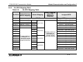
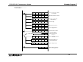
5.4.2
Module Parameterization and Configuration 5.
Rx-PDO Mapping Table
Table 5.5:
Rx-PDO#
Rx-PDO Mapping Table
Default Factory/
Mode 0 Mapping*
Mode A Mapping
Mode B Mapping
(after PDO
Mapping is
prepared)
COB ID
Assigned BFM
Mapped BFMs (access style)
Rx-PDO 1
0200 hex + node ID
181 hex
Rx-PDO 2
0300 hex + node ID
281 hex
Rx-PDO 3
0400 hex + node ID
381 hex
Rx-PDO 4
0500 hex + node ID
481 hex
BFM #15 ... BFM #12 (FROM)
Rx-PDO 5
182 hex
BFM #19 ... BFM #16 (FROM)
Rx-PDO 6
282 hex
Rx-PDO 7
382 hex
Rx-PDO 8
482 hex
Rx-PDO 9
Rx-PDO 10
Rx-PDO 11
Rx-PDO 12
Disabled (COB-ID set
to 80000000 hex).
These PDOs can be
activated by Mode B
mapping commands.
BFM #3 ... BFM #0 (FROM)
383 hex
BFM #11 ... BFM #8 (FROM)
BFM #103 ... BFM #100 (FROM)
Node 2 data
Disabled (COB-ID set
to 80000000 hex).
Can be defined by
mode B mapping
command parameter.
183 hex
283 hex
BFM #7 ... BFM #4 (FROM)
Node 1 data
Node 3 data
BFM #107 ... BFM #104 (FROM))
BFM #111 ... BFM #108 (FROM)
BFM #115 ... BFM #112 (FROM)
BFM #119 ... BFM #116 (FROM)
BFM #123 ... BFM #120 (FROM)
483 hex
BFM #127 ... BFM #124 (FROM)
Rx-PDO 13
184 hex
BFM #131 ... BFM #128 (FROM)
Rx-PDO 14
284 hex
Rx-PDO 15
384 hex
Rx-PDO 16
484 hex
Node 4 data
BFM #135 ... BFM #132 (FROM)
BFM #139 ... BFM #136 (FROM)
BFM #143 ... BFM #140 (FROM)
5-10
FX2N-32CAN Communication Module
Table 5.5:
Rx-PDO#
Module Parameterization and Configuration 5.
Rx-PDO Mapping Table
Default Factory/
Mode 0 Mapping*
Mode A Mapping
Mode B Mapping
(after PDO
Mapping is
prepared)
Assigned BFM
Rx-PDO 17
185 hex
Rx-PDO 18
285 hex
Rx-PDO 19
385 hex
Rx-PDO 20
485 hex
BFM #159 ... BFM #156 (FROM)
Rx-PDO 21
186 hex
BFM #163 ... BFM #160 (FROM)
Rx-PDO 22
Rx-PDO 23
Rx-PDO 24
Rx-PDO 25
Disabled (COB-ID set
to 80000000 hex).
These PDOs can be
activated by Mode B
mapping commands.
286 hex
386 hex
BFM #147 ... BFM #144 (FROM)
Node 6 data
486 hex
187 hex
Rx-PDO 26
287 hex
Rx-PDO 27
387 hex
Rx-PDO 28
487 hex
Rx-PDO 29
188 hex
Rx-PDO 30
288 hex
BFM #151 ... BFM #148 (FROM)
Node 5 data
Node 7 data
BFM #155 ... BFM #152 (FROM)
Disabled (COB-ID set
to 80000000 hex).
Can be defined by
mode B mapping command parameter.
BFM #167 ... BFM #164 (FROM)
BFM #171 ... BFM #168 (FROM)
BFM #175 ... BFM #172 (FROM)
BFM #179 ... BFM #176 (FROM)
BFM #183 ... BFM #180 (FROM)
BFM #187 ... BFM #184 (FROM)
BFM #191 ... BFM #188 (FROM)
Node 8 data
BFM #195 ... BFM #192 (FROM)
BFM #199 ... BFM #196 (FROM)
* The Factory Default Mapping contains only the first two Rx-PDOs and the first two Tx-PDOs
as defined in DS-301. Mode 0 mapping sets the first four Rx-PDOs and Tx-PDOs as shown in
the Tables.
5-11
FX2N-32CAN Communication Module
Module Parameterization and Configuration 5.
MEMO
5-12
FX2N-32CAN Communication Module
6.
Diagnostics
6.1
LED Status
Diagnostics 6.
To show that all LEDs are working, they will all be switched On for a short time after power On.
After that, the status of the LEDs depends on the LED status of the module.
6.1.1
The Power LED
The power LED is lit green when 5V power is supplied from the programmable controller. If it
is not lit, check to see if the extension cable is properly connected.
6.1.2
The FROM/TO LED
This LED is lit green when FROM/TO access is performed by the FX2N(C)/FX1N PLC to the
FX 2N -32CAN module. If there is no FROM/TO access for a longer period of time than is
specified in BFM #26, this LED will turn Off (FROM/TO WDT error).
Note: There are some cases where the FROM/TO instruction will be accessed on every scan
by an outside device. In these instances, the WDT error will not occur. Some examples of this
occurance are when the Special Function Unit’s Buffer Memory is being monitored by GX
Developer or another software program or if an FX1N-5DM is connected to an FX1N PLC.
As long as the FROM/TO WDT is refreshed, the FROM/TO LED will be On. After power On or
after a WDT error, the FROM/TO LED will be off until the next FROM/TO command is
registered. After the FROM/TO watchdog timer error has occurred, the value in the WDT
register (BFM #26) must be refreshed. Otherwise it is not possible to go online and exchange
valid data with the network.
6-1
FX2N-32CAN Communication Module
Diagnostics 6.
If an WDT error has occurred and FROM/TO traffic is recognized before BFM #26 is reset, the
FROM/TO LED will flicker.
If the WDT is disabled (BFM #26 = 0) and no FROM/TO command from the PLC are received,
the FROM/TO LED will be switched off 200ms after the last FROM/TO command was
processed.
6.1.3
The RUN LED
The RUN LED is controlled by the BUS_OFF and the BUS_OK state of the CAN controller.
When the module experiences too many transmission errors (for example, a baud rate
mismatch), it will go to the BUS_OFF state (CAN error number > 255). In the BUS_OFF state,
the RUN LED is OFF. After an internal software reset and a minimum of 128 bus free signals,
the module changes into BUS_OK state (RUN LED is ON).
6.1.4
The Rx/Tx LED
This LED lights up when the module is exchanging data. If the module is in the Preoperational state, the Tx/Rx LED is OFF. In the operational state, the Tx/Rx LED in ON. If an
internal queue overrun occurs, the TxRxLED will start to flicker.
6-2
FX2N-32CAN Communication Module
6.1.5
Diagnostics 6.
The ERROR LED
This LED lights up on a general error.
Check the CAN cable, the connectors, the end of the line terminal resistors, and the status of
the bus management mode. Also check BFM #29 for error bits. After the module enters the
data exchange state, if there are no errors and the module is in the BUS_OK state, the LED is
switched off.
In case of a BUS_OFF error, a general hardware error (BFM #29, bit 0) or if the FROM/TO
watchdog is expired, the LED will always be ON.
The LED will flicker if the FX2N-32CAN is in error passive state (CAN error counter >128) or on
an internal queue overflow.
A flickering ERROR LED does not mean there is a permanent error.
After the node changes from error passive to error active state the LED will be switched off.
In case of an transmit or command queue overflow the error is displayed until the
coresponding latched error flags (b8,b9) in BFM #29 are reset and no new queue overflow
occurs.
6-3
FX2N-32CAN Communication Module
Diagnostics 6.
MEMO
6-4
FX2N-32CAN Communication Module
7.
Example Program 7.
Example Program
The programs shown below are examples of how to set parameters and exchange data on the
CANopen Bus using the FX2N-32CAN module. The examples for Mode A Mapping in sections
7.3 and 7.4 can also be downloaded into two CANopen nodes and used to exchange data.
Please remember that these Mode “0”, “A”, and “B” Mapping Modes were developed to use
with the FX2N-32CAN modules and other CANopen nodes will not have these special settings.
Large networks or networks with many types of nodes can be configured more quickly and
easily if using a commercially available CANopen configuration tool.
The SDO write command in Section 7.1 gives an example of how to access the CANopen
Object Dictionary through the BFMs of the FX2N-32CAN module. The object dictionary can
also be accessed through a configuration tool.
7-1
FX2N-32CAN Communication Module
7.1
Example Program 7.
SDO Write Command
The CANopen Object Dictionary specifies where data and parameters are stored by Index and
Sub-Index number. Information can be stored or network parameters set/changed by writing
values to the appropriate Index and Sub-Index. The SDO command is one method to write the
data.
The programming example below shows how to write the command to start all nodes on
CANopen network bus. The code can be copied with appropriate data changes to perform
other SDO write commands.
M10
FNC 79
TOP
K0
K1001
K0
K1
1)
FNC 79
TOP
K0
K1002
H1F82
K1
2)
FNC 79
TOP
K0
K1003
H80
K1
3)
FNC 79
TOP
K0
K1004
K1
K1
4)
FNC 79
TOP
K0
K1005
K5
K1
5)
FNC 79
TOP
K0
K1000
K2
K1
6)
7-2
FX2N-32CAN Communication Module
Example Program 7.
1) The command must be passed through the BFM to the CANopen Object Dictionary. Node
“0” is used to default to the local node. In general this BFM is used to specify which node
number (1~127) is the target for the SDO access.
2) Write the Index number. In this example, H18F2 is the node start up command index. In
order to perform other network functions, please study the CANopen Object Dictionary and
write to the appropriate Index.
3) Write to the Sub-index. In this example, the nodes to be started is decided and the value
80H defaults to “all nodes”.
4) Write the amount of data to be transferred. The value K1 means that one byte of data will
be transferred.
5) Write the actual data to be transferred, the low byte of BFM #1005 = 1st data Byte; high
byte of BFM #1005 = 2nd data Byte. The value 5H is the signal to turn on the specified
nodes.
6) Write the data to the CANopen network. Up to this point, the data has only been stored in
the FX2N-32CAN BFMs.
7-3
FX2N-32CAN Communication Module
7.2
Example Program 7.
Mode 0 Mapping Command
Initial Pulse
M8002
M10
FNC 79
TO
K0
K27
K6
K1
Set the Node number
FNC 79
TO
K0
K24
K1000
K1
Set the Baud Rate to
1000Kbaud
FNC 79
TO
K0
K26
K20
K1
Set the Watch Dog Timer
FNC 79
TO
K0
K1000
H8900
K1
Set Mode 0 Mapping Command
FNC 78
FROM
K0
K1000
D100
K1
Read Parameter Set Status
SET
M10
M10
D=
M10
D100 H8901
Check that CANopen
parameters have been
correctly set
FNC 78
FROM
K0
K0
D0
K1
Read Data Received from the
CAN Bus
FNC 79
TO
K0
K8
H2222
K1
Write Transmit Data to the
FX2N-32CAN Module
FNC 79
TO
K0
K20
K1
K1
Refresh CANopen Data
MOV
D0
K4Y000
M10
Transfer data to the Outputs
(for monitoring purposes)
7-4
FX2N-32CAN Communication Module
7.3
Example Program 7.
Mode A Mapping Example
Initial
Pulse
M8002
M10
FNC 79
TO
K0
K27
K1
K1
Set the Node number.
FNC 79
TO
K0
K24
K1000
K1
Set the Baud Rate to
1000Kbaud
FNC 79
TO
K0
K26
K20
K1
Set the Watch Dog Timer
to 200 ms
FNC 79
TO
K0
K1000
H8200
K1
Set Mode A Mapping Command
FNC 78
FROM
K0
K1000
D100
K1
Read Parameter Set Status
SET
M10
Check that CANopen
parameters have been
correctly set
M10
D=
M10
D100 H8201
FNC 79
TO
K0
K1
HFFFF
K1
Write Transmit Data to the
FX2N-32CAN Module
FNC 79
TO
K0
K20
K1
K1
Refresh CANopen Data
FNC 78
FROM
K0
K19
DO
K1
Read Data Received from the
CAN Bus
MOV
D0
K4Y000
M10
Transfer data to the Outputs
(for monitoring purposes)
7-5
FX2N-32CAN Communication Module
7.4
Example Program 7.
Mode A Mapping with Node Start Up Command
Initial
Pulse
M8002
M10
FNC 79
TO
K0
K27
FNC 79
TO
K0
K24
FNC 79
TO
K0
FNC 79
TO
FNC 78
FROM
K2
K1
Set the Node number
K1000
K1
Set the Baud Rate to
1000 Kbaud
K26
K20
K1
K0
K1000
H8200
K1
Set Mode A Mapping Command
K0
K1000
D100
K1
Read Parameter Set Status
SET
M10
M10
D=
M10
D100 H8201
Set the Watch Dog
Timer to 200 ms
Check that CANopen
parameters have been
correctly set
FNC 79
TOP
K0
K1001
K0
K1
Access local Node ("0" defaults
to local node)
FNC 79
TOP
K0
K1002
H1F82
K1
Initiate Node startup Command
FNC 79
TOP
K0
K1003
H80
K1
Set Nodes to Start ("H80"
starts all Nodes)
FNC 79
TOP
K0
K1004
K1
K1
Set Data Length
FNC 79
TOP
K0
K1005
K5
K1
Start Node(s) Command
FNC 79
TOP
K0
K1000
K2
K1
Command Code for SDO
Write Access
7-6
FX2N-32CAN Communication Module
Example Program 7.
Continued.............
K10
M10
Set Timer T20 to 1 second
T20
T20
M10
INCP
D10
Increment Value in D10
RST
T20
Reset T20
FNC 79
TO
K0
K3
D10
K1
Write Transmit Data to the
FX2N-32CAN Module
FNC 79
TO
K0
K20
K1
K1
Refresh CANopen Data
FNC 78
FROM
K0
K1
DO
K1
Read Data Received from the
CAN Bus
MOV
D0
K4Y000
M10
Transfer data to the Outputs
(for monitoring purposes)
7-7
FX2N-32CAN Communication Module
7.5
Example Program 7.
Mode B Mapping Example with SDO Command
Initial Pulse
M8002
FNC 79
TO
K0
K27
K5
K1
Set the Node Number
FNC 79
TO
K0
K24
K1000
K1
Set the Baud Rate
FNC 79
TO
K0
K26
H20
K1
Set the Watch Dog Timer
FNC 79
TO
K0
K1001
H0
K1
PDO Initial Parameter Set
Command
FNC 79
TO
K0
K1002
H0
K1
PDO Initial Parameter Set
Command
FNC 79
TO
K0
K1003
H501
K1
PDO Source Mapping Command
FNC 79
TO
K0
K1004
H601
K1
PDO Destination Mapping
Command
FNC 79
TO
K0
K1005
H603
K1
PDO Source Mapping Command
FNC 79
TO
K0
K1006
H513
K1
PDO Destination Mapping
Command
FNC 79
TO
K0
K1007
HFFFF
K1
Command to signal the end of
the PDO Mapping
FNC 79
TO
K0
K1000
H8300
K1
Set Mode B Mapping Command
7-8
FX2N-32CAN Communication Module
Example Program 7.
Continued.............
M10
M10
FNC 79
TOP
K0
K1001
K0
K1
Access local Node ("0" defaults
to local node)
FNC 79
TOP
K0
K1002
H1F82
K1
Initiate Node startup Command
FNC 79
TOP
K0
K1003
H80
K1
Set Nodes to Start ("H80"
starts all Nodes)
FNC 79
TOP
K0
K1004
K1
K1
Set Data Length
FNC 79
TOP
K0
K1005
K5
K1
Start Node(s) Command
FNC 79
TOP
K0
K1000
K2
K1
Command for SDO Write
Access
FNC 78
FROM
K0
K1000
D100
K1
Read Parameter Set Status
SET
M10
M10
D=
M10
D100 H8301
Check that CANopen
parameters have been
correctly set
FNC 78
FROM
K0
K152
D0
K1
Read Data Received from the
CAN Bus
FNC 79
TO
K0
K0
H1111
K1
Write Transmit Data to the
FX2N-32CAN Module
FNC 79
TO
K0
K20
K1
K1
Refresh CANopen Data
MOV
D0
K4Y000
M10
Transfer data to the Outputs
(for monitoring purposes)
7-9
FX2N-32CAN Communication Module
Example Program 7.
MEMO
7-10
FX2N-32CAN Communication Module
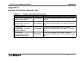
Appendix A:
Appendix A:
Further Information Manual Lists
Table A-1:
Further Information Manual Lists
Manual name
Manual No.
Description
FX2N-32CAN Communication
Module User’s Mnaual
JY992D92801
FX2N Series
Programmable Controllers
Hardware Manual
This manual contains explanations for wiring,
JY992D66301 installation and specification, etc. about FX2N Series
PLC.
FX1N Series
Programmable Controllers
Hardware Manual
This manual contains explanations for wiring,
JY992D89301 installation and specification, etc. about FX1N Series
PLC.
FX Series of
Programmable controllers
Programming Manual ΙΙ
This manual contents text is written instruction
JY992D88101 expranations of FX1S, FX1N, FX2N and FX2NC Series
PLC.
This manual contents expanations for BFM of FX2N32CAN.
A-1
FX2N-32CAN Communication Module
Appendix A:
MEMO
A-2
HARDWARE MANUAL
FX2N-32CAN Communication Module
HEAD OFFICE: TOKYO BUILDING, 2-7-3 MARUNOUCHI, CHIYODA-KU, TOKYO 100-8310, JAPAN
HIMEJI WORKS: 840, CHIYODA CHO, HIMEJI, JAPAN
JY992D92901C
(MEE)
Effective May 2006
Specification are subject to change without notice.