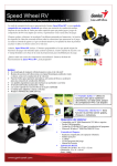
1
Installation tutorial for Console Customs Xbox 360
MaxFire – FUSION V3 rapid fire Mod Chip.
This tutorial is designed to aid you in installation of a console customs MaxFire FUSION V3 modchip. This tutorial covers the
installation of our new 14-pin chip . This chip only works with “common Ground” style wireless controllers. The first part of this
tutorial shows how to find if your controller is a common ground style. This chip will not work with matrix style controllers.
This installation requires soldering several wires to extremely small confined spaces. We do not advise attempting this installation if
you are a beginner at soldering. We recommend reading through all of the instructions and understand them before beginning
your installation.
WARNING: Please proceed with this installation at your own risk. We will not be held responsible for any damage to
yourself, your controller, your Xbox 360 console or any other equipment.
This tutorial requires opening your controller which will void the warranty of your controller.
Tools needed:
•
Torx T8 Security/tamper proof driver (For opening wireless controller)
•
•
•
Soldering iron (A 15w/30w from radio shack is about $12)
Solder (We use rosin core solder from radio shack so there is no need for flux $4)
Wire strippers (that can strip 30ga wire, a 30ga wire wrap tool from radio shack includes a 30ga stripper $8)
•
•
Wire cutters
•
Hot glue gun
9/64th drill bit (or close to it, a 1/8th will also work)
•
Small pocket knife or razor blade
Please visit our website at www.consolecustoms.com
For questions or help please email us at [email protected]
Sending pictures with support requests will help to help you quickly!
Controller Identification
• Before you get started you need to make sure that you have the correct controller type for this installation. Our MaxFire FUSION
Chip requires a CG or CG2 PCB inside your controller. This chip CANNOT be installed into a matrix style controller. The Left side
images show the board from behind the battery door (no need to open the controller) and the right side is with the controller open.
Matrix PCB
From the battery door area you
can see that there is no
Capacitor on the left side while
the other two versions do have a
capacitor.
CG PCB
From the battery door area you
can see that the Capacitor is
horizontally oriented.
CG2 PCB
From the battery door area you
can see that the capacitor is
vertically oriented.
Step 1: First lets start by looking at what is in your kit.
•
You should have the following items in your kit
1. (1) 14 pin PIC microcontroller
2. (1) Button
3. 30ga. Wire ( We include multiple colors)
Step 2: You will start by taking the PIC chip and putting it on its back, also called
(dead bug). Note the location of the notch that is on the top of the chip, the pin
numbers and their purpose.
Notch
Power
Ground
14
1
right trigger
13
2
B Button
12
3
Y Button
11
4
Mod Button
X Button
10
5
RB Button
9
6
8
7
Player 4 LED
Player 3 LED
A Button
Right Thumbstick Click
“Back” Button
Left trigger
Step 3a: You will now attach the wires to the chip using solder.
We use several color wires here to help show where each wire goes. Your kit will contain 4-5 colors of wire.
Starting with pins 1-7:
• Pin 1: This is the power wire and is red in the image, this
wire should be 2 inches long.
• Pin 2: This is the short green wire and is for the A button, this
wire should be 1.5” long.
• Pin 3: This is the yellow wire and will go the right
thumbstick Click, this wire should be 1.5” long.
• Pin 4: This is the whitewire and will goto the Mod button,
This wire should be 2” long.
Notch
• Pin 5: This is the long red wire and will go to the RB button,
this wire should be 3” long
• Pin 6: This is the blue wire and will go to the controllers
“back” button, this wire should be 4” long
• Pin 7: This is the long green wire will go to the Left trigger,
this wire should be 5” long
• Tip: Only strip about 1/8” of the wire for soldering. Exposing
more bare wire could cause a short.
•Tip: Use a pair of self closing tweezers to hold the chip.
• Tip: For information on proper soldering visit
http://www.curiousinventor.com/guides/How_To_Solder
Pin 7
Pin 1
Step 3b: Continuing to the other side of the chip.
pins 8-14:
• Pin 8: This is the long yellow wire for the Player 3 LED and
should be 2.25 inches long.
• Pin 9: This is the long white wire for the Player 4 LED and
should be 2 inches long.
• Pin 10: This is the long blue wire for the X button and should
be 1.5 inches long.
• Pin 11: This is the short yellow wire for Y button and should
be 2 inches long.
• Pin 12: This is the Red wire for B button and should be 2
inches long.
• Pin 13: This is the short blue wire for right trigger and should
be ¾ of an inch long.
• Pin 14: This is the short white wire which will go to ground
and should be ¾ of an inch long.
•tip: Only strip about 1/8” of the wire for soldering. Exposing
more bare wire could cause a short.
Notch
•tip: For information on proper soldering visit
http://www.curiousinventor.com/guides/How_To_Solder
Pin 14
Pin 8
Step 4: Opening the controller
• Remove the 7 screws indicated below. One is behind the small white label.
• The wireless controller requires a T8 Torx security driver. This is a star shaped tip with a hole in the middle
of it. It is very difficult to open the wireless controller without this.
WIRELESS
SCREWS
Step 5: Prep the X, Y, B, A and Back button solder areas
All images shown in this guide are of a CG2 board but all locations are exactly
the same for both CG and CG2 boards.
• To connect the wires from the chip to the X, Y, B and Back buttons you will need to first need to remove some
of the black carbon coting that is coving the pads. This is easiest done with a small pocket knife or razor
blade. Lightly scrape the coating to expose the bare copper underneath. Be carefully to only scrape the
coating from the edge of the pad we want the wire as close to the edge as possible so that the wire and
solder do not interfere with the operation of the button.
B
Y
X
BACK
A
Step 6: Tin the solder pads
• Next you will want to Tin the pads. Tinning is basically coating the exposed copper with solder. This makes
connecting the wire later much easier. To do this you will want to place the tip of your soldering iron on the
pad to heat the pad and touch the solder to the pad (try avoiding touching the solder to the soldering iron) and
the solder should flow onto the pad. You should end of with little bubbles of solder like you see below. You
want to keep the solder to a minimum so that the button still feel the same and function properly. The right side
image is a side shot so you can see that we only have a small bubble of solder. If you have a big tall bubble
you will want to remove some of the solder.
Step 7: Mounting the chip to the circuit board using hot glue.
• Mount the chip on it’s back (dead bug) with hot glue so it is exactly in-between the thumbstick
and the large hole to the right. The chip will sit on top of the pins from the rumble motor, so you
will need to be sure to use enough hot glue to hold it in place.
• Note the orientation from the location of the notch that is on the top of the chip.
Notch
Step 8: Attaching the LED wires.
Now lets start connecting our wires. We will start with the wires to control the Player 3 and 4 LEDs. Be sure to cut
the wires to the exact length needed and keep the wires out of the black circles on the board.
• Solder the yellow wire from Pin 8 to the bottom of the player 3 LED. You must be careful with this as the LED’s are
very fragile and leaving your soldering iron on the end to long could damage the LED. Only touch the very end of
the LED with your soldering iron. DO NOT touch the longer sides or the center of the LED because this will
destroy it.
• Next Solder the white wire from Pin 9 to the bottom of the Player 4 LED.
• Tip: keep your wires as short as possible and follow the path use use below. This will prevent problems with
button operation and allow the controller to close properly without pinching wires.
Step 9: Soldering the X, Y, A and B button wires.
• Now you will need to attach the X (pin 10), Y (pin 11) and B (pin 12) and A (Pin 2) button wires. It is again very
important to keep the wires as short as possible and keep them out of the black circles. If you cross over a
black circle it could possibly prevent one of the buttons on your controller from working when you put it back
together. Solder the wire so that it is along the edge as we have done here
Step 10: soldering the right trigger wire and ground wire.
• In this step you will first solder the white ground wire from Pin 14 to the bottom of the 3 trigger pins that are
located directly above the chip.
• Then solder the blue right trigger wire from pin 13 to the middle of the 3 trigger pins.
Notch
Ground
Right
Trigger
Step 11: Solder the left trigger wire.
• In this step you will need to take the green wire from pin 7 and first run it along the bottom of the
circuit board as shown in the left image. Use some hot glue to hold the wire in place so that it does
not catch on anything when putting the controller back together.
• Next trim the wire so that you do not have extra wire and strip only 1/8” of the end of the wire.
Then use your soldering iron to attach the wire to the middle of the three trigger pins as show in the
right side image.
Tip: trim you wires so they are only as long as you need, then strip the end and solder into place. Long wires will
just cause a place for something to snag when closing the controller.
Hot glue Here
Solder to
middle of the
3 trigger pins
Step 12: Solder the ‘back” button wire.
• Solder the wire from pin 6 (blue wire) to the pad for the back button as shown. Follow
the same route as the player 3 and 4 LED wires.
• We added a little dab of hot glue here as well just to keep everything in place.
Hot glue Here
Step 13: Attaching the RB Button wire.
• Solder the wire from pin 5 (red wire) to the top of the RB Button as shown. You must be careful
and make sure that the wire or solder does not make contact to the metal back support for the RB
button.
• Again make sure the wire is kept short and out of the path of the black circles.
Step 14: Soldering the right thumbstick click wire.
• Flip over the controller and solder the wire from pin 3 (yellow wire) to the pin on the back side for
the right thumbstick click.
Step 15: Soldering the power wire.
• Solder the red wire from pin 1 to the power for the headset as shown. The bottom
picture shows a close-up of the solder point
Solder Here
Plastic clip from headset
Step 16: Onto the case and button. Here we will drill the hole needed for the
button and secure it in place.
• Drill a hole using your drill bit in the spot indicated or where ever you would like to have your button. We prefer
keeping it out of the way because you will only need to press it to change modes.
• Next take your button and we are going to remove one pair of legs
because we only need one pair. Use the image to the right so you know which
legs to remove.
•Next use hot glue to secure the button in place. Do not attempt to use super glue
or other adhesives as it will soak into the button mechanism and cause it to stop
working. Once the button is secured in place bend the two legs out flat away from
the button.
• finally cut another small piece of wire about 2” long and solder to one leg of the
button. This will later be connected to the ground in the controller.
Drill hole here
REMOVE
Step 17: We will now connect the wire from the chip to the button.
• flip over the controller PCB and bring it in close to the back half of the case. Take the one wire that
you have left (White wire from pin 4) and solder it to the remaining pin of the button.
• Finally flip the PCB over onto the back of the case and attach the final wire from the button to
ground. We attach this by scraping some of the green coating from the circuit board along the edge
and soldering the wire. Any of the “honeycomb” area is part of a ground plane and can be scraped
and soldered to for ground.
To ground
From Pin 4
Ground wire
from button
Step 18: Almost done
•
Now onto the top of the case. To make it all fit we may have to make a little bit more room for the chip.
Using a knife or side cutters remove the plastic support shown in the image in red. This is the angled
support for the right side rumble motor.
•
The last thing you need to do is reassemble everything. The easiest way we have found to do this is leave
the top piece face down so all the buttons do not fall out. And hold the circuit board to the back of the
controller and flip it over on the top of the case. Align the rumble motors so they are in their holders and
lay the PCB and back of the case onto the front of the case. Keep it face down and use your finger to
work the thumbsticks through the holes and work the case closed. Do not force it, you may have wires
preventing the case from closing entirely. Just go slow and look at any areas to see what is stopping it
from closing all the way.
•
Now just screw your controller back together and your done! Click the link to se the user guide for you
new mod chip. MaxFire Fusion V3 User Manual