1
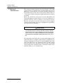
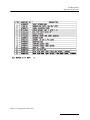
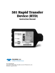
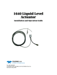
674 Rain Gauge
Installation and Operation Guide
Part #60-3283-011
Copyright © 1992, 2004. All rights reserved, Teledyne Isco, Inc.
Revision J, April 18, 2011
Foreword
This instruction manual is designed to help you gain a thorough understanding of the
operation of the equipment. Teledyne Isco recommends that you read this manual
completely before placing the equipment in service.
Although Teledyne Isco designs reliability into all equipment, there is always the possibility of a malfunction. This manual may help in diagnosing and repairing the malfunction.
If the problem persists, call or e-mail the Teledyne Isco Technical Service Department
for assistance. Simple difficulties can often be diagnosed over the phone.
If it is necessary to return the equipment to the factory for service, please follow the
shipping instructions provided by the Customer Service Department, including the
use of the Return Authorization Number specified. Be sure to include a note
describing the malfunction. This will aid in the prompt repair and return of the
equipment.
Teledyne Isco welcomes suggestions that would improve the information presented in
this manual or enhance the operation of the equipment itself.
Teledyne Isco is continually improving its products and reserves the right to
change product specifications, replacement parts, schematics, and instructions without notice.
Contact Information
Customer Service
Phone:
(800) 228-4373
(USA, Canada, Mexico)
(402) 464-0231
(Outside North America)
Fax:
(402) 465-3022
Email:
[email protected]
Technical Support
Phone:
Email:
(800) 775-2965
(Analytical)
(866) 298-6174
(Samplers and Flow Meters)
[email protected]
Return equipment to: 4700 Superior Street, Lincoln, NE 68504-1398
Other Correspondence
Mail to:
P.O. Box 82531, Lincoln, NE 68501-2531
Email:
[email protected]
Web site:
www.isco.com
Revised March 17, 2009
674 Rain Gauge
Table of Contents
Operation Instructions
1.1
1.2
1.3
1.4
1.5
1.6
1.7
1.8
1.9
Description and Operation . . . . . . . . . . . . . . . . . . . . . . . . . . . . . . . . . . . . . . . . . . . .
Applications . . . . . . . . . . . . . . . . . . . . . . . . . . . . . . . . . . . . . . . . . . . . . . . . . . . . . . . .
Materials and Construction . . . . . . . . . . . . . . . . . . . . . . . . . . . . . . . . . . . . . . . . . . .
Location of the Rain Gauge . . . . . . . . . . . . . . . . . . . . . . . . . . . . . . . . . . . . . . . . . . .
1.4.1 Suggested Siting . . . . . . . . . . . . . . . . . . . . . . . . . . . . . . . . . . . . . . . . . . . . . .
Installation . . . . . . . . . . . . . . . . . . . . . . . . . . . . . . . . . . . . . . . . . . . . . . . . . . . . . . . .
Maintenance . . . . . . . . . . . . . . . . . . . . . . . . . . . . . . . . . . . . . . . . . . . . . . . . . . . . . . .
Electrical Considerations . . . . . . . . . . . . . . . . . . . . . . . . . . . . . . . . . . . . . . . . . . . . .
Technical Specifications . . . . . . . . . . . . . . . . . . . . . . . . . . . . . . . . . . . . . . . . . . . . . .
Replacement Parts List. . . . . . . . . . . . . . . . . . . . . . . . . . . . . . . . . . . . . . . . . . . . . . .
1-1
1-1
1-1
1-2
1-2
1-2
1-3
1-4
1-5
1-5
List of Tables
1-1 Technical Specifications for the 674 Rain Gauge . . . . . . . . . . . . . . . . . . . . . . . . . . 1-5
List of Figures
1-1 Replacement Parts List Illustration . . . . . . . . . . . . . . . . . . . . . . . . . . . . . . . . . . . . 1-6
1-2 Replacement Parts List . . . . . . . . . . . . . . . . . . . . . . . . . . . . . . . . . . . . . . . . . . . . . . 1-7
i
674 Rain Gauge
Table of Contents
ii
674 Rain Gauge
Operation Instructions
1.1 Description and
Operation
The Isco 674 Rain Gauge is a precision instrument for accurately
measuring rainfall. The rain gauge is mounted inside a steel cylinder and has an eight-inch opening on top to collect rain. Rain
falls through a screen into a funnel. From the funnel, rain collects in one side of a two-chambered plastic bucket mounted on
jewelled pivots. When rain fills the chamber, the bucket tips,
draining the water and exposing the other chamber to fill. When
that chamber fills, the bucket tips back and the process begins
again.
Each time the bucket tips from one side to the other, a magnet
passes over a reed switch, momentarily closing the normally
open contacts. This contact closure provides a short-duration
output pulse from the rain gauge for each 0.01 inch of rain.
1.2 Applications
When connected to a flow meter, the rain gauge enables the flow
meter to print rainfall data on its chart or store rainfall data in
memory. It also lets the flow meter actuate an associated Isco
Automatic Wastewater Sampler.
Typical applications include monitoring of storm water runoff,
inflow and infiltration studies (I&I), and combined sewer
overflow monitoring. You can also use the rain gauge for any
other general purpose rainfall measurement as long as the associated equipment is electrically compatible.
1.3 Materials and
Construction
The rain gauge is constructed of steel, stainless steel, aluminum,
and plastic. All metal parts are coated, plated, or painted to
ensure a durable, ruggedly tough instrument capable of resisting
deterioration from exposure to the elements. Screens cover all
openings, preventing clogging by leaves, insects, or other debris.
The powder-coated steel sleeve protects the internal parts. The
jewelled-pivot mounting for the tipping bucket provides long life.
A built-in bubble level makes leveling the rain gauge after installation easy. A 50-foot cable terminated in an M/S connector
attaches the rain gauge to the flow meter or to other equipment.
CAUTION
The rain gauge is factory-calibrated and adjusted. Do not
attempt to make any adjustments to the jewelled-pivot screws.
You may damage the jewel bearings.
1-1
674 Rain Gauge
Operation Instructions
1.4 Location of the Rain
Gauge
Location affects the accuracy of the rainfall catch because the
prevailing winds may tend to carry the rain away from the
gauge. There are advantages and disadvantages to most sites.
Sites may be either open or protected. Totally open sites affect
the accuracy of the catch if the rain is carried on strong winds,
but are satisfactory if rainstorms are generally calm. With no
nearby vegetation the characteristics of the site will not tend to
change over time, which is an advantage. Where strong winds
are characteristic of storms, protected sites are generally preferable. This is because the effect of the wind on the rainfall catch
is reduced. The presence of small groups of objects or objects of
varying heights around the gauge can also affect accuracy by producing eddy currents in the wind which will interfere with the
catch.
1.4.1 Suggested Siting
Groups of objects of uniform height (such as trees) in the vicinity
of the gauge are beneficial for an accurate catch by acting as a
windbreak while not interfering with the catch. Mounting the
rain gauge in the clearing of an orchard or a grove of trees would
be a recommendation for a good site.
The height of the surrounding objects should not exceed twice
their distance from the rain gauge. If vegetation serves as a
windbreak, understand that growth will greatly change the conditions of the site with the passage of time. What may originally
have been a good site may not always remain one.
Vegetation grows dramatically over time. Any construction
nearby that takes place after the installation may also make a
site undesirable by altering the wind currents and rainfall patterns around the gauge. Under no circumstances should any
nearby object be allowed to grow above or hang directly over the
gauge.
The rain gauge is solidly built to withstand years of outside use;
however, vandals could ruin it. Always try to install the rain
gauge where it will be protected from vandalism.
Avoid installation in low places where runoff from heavy storms
could flood the gauge or wash it away. The rain gauge would not
be hurt by submersion, but it would be unable to measure.
Do not drop the rain gauge or expose it to shock; that could
damage the jeweled bearings.
1.5 Installation
To install the rain gauge, follow the procedure below. Step 7 is
optional, depending on the requirements of your particular
installation.
1. Unpack the rain gauge from the shipping box. Save the box
and packing to return the rain gauge to Isco if that
becomes necessary. Remove the outer tube (white cover
with funnel) from the rain gauge by loosening the two
thumb screws on either side.
2. Locate the bottom (mounting) plate of the rain gauge. This
is circular and made of black metal. Mount this plate
securely to a stable horizontal surface that is relatively
1-2
674 Rain Gauge
Operation Instructions
level. Isco suggests using corrosion-resistant hardware for
mounting. The mounting holes will accommodate hardware as large as ¼ inch in diameter.
3. This is very important: Level the rain gauge by adjusting
the three thumb screws on the base until the bubble in the
bubble level is exactly centered.
4. Carefully remove the rubber band used to secure the tipping bucket assembly. Do not apply pressure to the bucket
or the pivot arm. Do not attempt any adjustments.
5. Reinstall the protective outer tube on the rain gauge.
6. Route the cable from the rain gauge to the flow meter. Coil
any extra wire by the flow meter.
7. If necessary, you can increase the distance between the
flow meter and the rain gauge to 1,000 feet (maximum) by
splicing a two-wire #18 AWG cable (user- supplied)
between the Isco-provided cable and the rain gauge, as
described below.
Disconnect the Isco cable from the terminal block inside
the rain gauge and splice the user-supplied cable to that
end of the Isco cable. If the wiring and the splice will be
exposed to the weather, use wire appropriate for outdoor
use and insulate the splice properly. A weatherproof box
may be necessary. Do not cut the M/S connector from the
Isco cable unless you are connecting the rain gauge to
equipment that does not have a compatible connector. You
will not be able to reconnect it easily.
1.6 Maintenance
The Isco Rain Gauge is built of quality materials to withstand
years of exposure to the elements. Normally, no maintenance is
required.
Once a year (or more often if conditions warrant) you may want
to remove the cover and check the gauge to see that it has not
been affected by the buildup of dust, debris, or insect infestation.
The rain gauge is factory-calibrated and needs no further
adjustment. If your installation is temporary and you intend to
move the rain gauge from site to site, use care in transporting
the unit. Again, you could damage the jewelled pivots for the
tipping bucket if you expose the rain gauge to a severe shock - for
example, by dropping it. If you move the rain gauge frequently,
always secure the tipping bucket with a rubber band and use the
original packing box to protect the unit during transport.
Repack the rain gauge as it was originally shipped to you if you
need to return it to Isco.
1-3
674 Rain Gauge
Operation Instructions
1.7 Electrical
Considerations
The electrical output from the Isco Rain Gauge is the rapid
contact closure of a normally open reed switch. The rain gauge is
not itself a powered device. It contains neither batteries nor
transformer and does not connect to the AC line. Electrically, it is
a “dry contact” switch, with power supplied from whatever device
it controls.
When you connect the rain gauge to an Isco Flow Meter, the
current through the switch contacts is very low and there is no
problem with line losses or damage to the switch contacts.
However, if you plan to use the rain gauge for general-purpose
rain measurement with other types of equipment not specified by
Isco, please note the following:
CAUTION
The reed switch is rated for pilot duty only! The sealed contacts
are limited to 10 watts (or 10 VA), 200 VDC maximum. Exceeding these limits may cause welding or rupturing of the reed
switch, ruining it. For safety considerations, Isco recommends
connection only to equipment supplying 30 volts or less, AC or
DC.
Be particularly careful using the rain gauge with equipment supplying DC voltages at higher current loads or equipment presenting an inductive load to the reed switch. Never connect the
rain gauge directly to any equipment where enough current
passes to strike an arc when the contacts switch. You should
always buffer such equipment with a solid-state switch (transistor, IC, SCR, etc.) or a sensitive relay.
1-4
674 Rain Gauge
Operation Instructions
1.8 Technical
Specifications
The technical specifications for the 674 rain gauge are presented
in Table 1-1.
Table 1-1 Technical Specifications for the 674 Rain Gauge
Type:
Tipping bucket
Orifice:
8 inches (20 cm) diameter
Sensitivity:
English: 0.01 inches
Metric: 0.1 mm
Accuracy:
English: ± 1% at 2 inches/hr; +3, -4% up to 5 inches/hr
Metric: ± 1½% at 5 cm/hr; +3.5, -9% up to 13 cm/hr
Maximum Capacity:
English: 22 inches/hr
Metric: 38 cm/hr
Connector Pinout:
Pin A - Red, +12V DC from Flow Meter;
Pin D - Black, Output from Rain Gauge
Output Signal:
Contact closure, 50 milliseconds minimum duration
Switch Type:
Hermetically sealed magnetic reed switch. Normally open.
200V DC, 0.5 A maximum
Height and Diameter:
13 inches (33 cm); 9½ inches (24 cm) at base
Weight:
10 pounds (4.5 kg)
Operating Temperature:
32° to 140° F (0° to 60° C)
Storage Temperature:
-40° to 140° F (-40° to 60° C)
1.9 Replacement Parts
List
The following pages contain a list of replacement parts for the
Isco 674 rain gauge. The illustration shows the location of the
numbered parts, which are described in the accompanying table.
Replacement parts can be purchased by contacting Isco’s Customer Service Department.
Isco, Inc.
Customer Service Department
P.O. Box 82531
Lincoln, NE 68501 USA
Phone: (800) 228-4373
(402) 464-0231
FAX: (402) 465-3022
E-mail: [email protected]
1-5
674 Rain Gauge
Operation Instructions
Figure 1-1 Replacement Parts List Illustration
1-6
674 Rain Gauge
Operation Instructions
Figure 1-2 Replacement Parts List
1-7
674 Rain Gauge
Operation Instructions
1-8
Warranty
Teledyne Isco One Year Limited Warranty*
Factory Service for Teledyne Isco Flow Meters, Waste Water Samplers, and Syringe Pumps
This warranty exclusively covers Teledyne Isco
instruments, providing a one-year limited warranty
covering parts and labor.
Any instrument that fails during the warranty period due to
faulty parts or workmanship will be repaired at the factory
at no charge to the customer. Teledyne Isco’s exclusive
liability is limited to repair or replacement of defective
instruments. Teledyne Isco is not liable for consequential
damages.
Teledyne Isco will pay surface transportation charges both
ways within the 48 contiguous United States if the
instrument proves to be defective within 30 days of
shipment. Throughout the remainder of the warranty period,
the customer will pay to return the instrument to Teledyne
Isco, and Teledyne isco will pay surface transportation to
return the repaired instrument to the customer. Teledyne
Isco will not pay air freight or customer’s packing and
crating charges. This warranty does not cover loss, damage,
or defects resulting from transportation between the
customer’s facility and the repair facility.
The warranty for any instrument is the one in effect on date
of shipment. The warranty period begins on the shipping
date, unless Teledyne Isco agrees in writing to a different
date.
Excluded from this warranty are normal wear; expendable
items such as charts, ribbon, lamps, tubing, and glassware;
fittings and wetted parts of valves; and damage due to
corrosion, misuse, accident, or lack of proper maintenance.
This warranty does not cover products not sold under the
Teledyne Isco trademark or for which any other warranty is
specifically stated.
No item may be returned for warranty service without a
return authorization number issued by Teledyne Isco.
This warranty is expressly in lieu of all other warranties
and obligations and Teledyne Isco specifically disclaims
any warranty of merchantability or fitness for a
particular purpose.
The warrantor is Teledyne Isco, Inc. 4700 Superior,
Lincoln, NE 68504, U.S.A.
* This warranty applies to the USA and countries where Teledyne Isco Inc. does not have an authorized
dealer. Customers in countries outside the USA, where Teledyne Isco has an authorized dealer, should
contact their Teledyne Isco dealer for warranty service.
Before returning any instrument for repair, please call, fax, or e-mail the Teledyne Isco Service
Department for instructions. Many problems can often be diagnosed and corrected over the
phone, or by e-mail, without returning the instrument to the factory.
Instruments needing factory repair should be packed carefully, and shipped to the attention of
the service department. Small, non-fragile items can be sent by insured parcel post. PLEASE
BE SURE TO ENCLOSE A NOTE EXPLAINING THE PROBLEM.
Shipping Address:
Mailing Address:
Phone:
Fax:
Email:
Teledyne Isco, Inc. - Attention Repair Service
4700 Superior Street
Lincoln, NE 68504 USA
Teledyne Isco, Inc.
PO Box 82531
Lincoln, NE 68501 USA
Repair service:
(800) 775-2965 (lab instruments)
(866) 298-6174 (samplers & flow meters)
Sales & General Information: (800) 228-4373 (USA & Canada)
(402) 465-3001
[email protected]
March 8, 2011 P/N 60-1002-040 Rev E