1
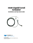
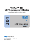
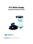
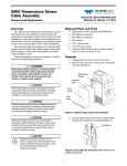
Pressurized Line Liquid Sampling System Instruction Sheet #60-5314-748 Revision A, April 15, 2011 For 6712 and Avalanche Samplers Overview Setup and Installation The pressurized line sampling system for Isco 6712 and Avalanche water samplers consists of the sampler with software option SPA 1376, a relay alarm box, a 3-way actuated ball valve, an aluminum mounting plate, and, if pressures will be in excess of 15 psi, a pressure reduction valve. The system supports sampling from pipes with pressures up to 300 psi. Programming Operation A normal sample routine consists of the sampler pumping first in reverse (pre-purge), then forward (bottle fill), and reverse again (post-purge). When the sampler runs forward, it sends a signal to the relay alarm box (see the instructions under Programming for initializing the sampler software enhancement to activate this function). The alarm box alerts the 3-way valve to allow pumping of the sample liquid. During pre-purge and post-purge, the valve causes the remaining liquid between itself and the sampler to be discharged through the third port into the user-supplied drain. Pressures exceeding 15 psi must be reduced prior to reaching the 3-way valve to maintain accurate sample volumes and avoid damage to the system. Isco offers a stainless-steel pressure reduction valve with 1/2" NPT fittings. Site Requirements The discharge drain must be routed to a point at or near zero pressure for complete purging and prevention of cross-contamination between samples. The Isco pressure reduction valve is not recommended for sample sources containing solids, or with viscosities higher than that of no. 2 oil. The user is responsible for any pre-filtering required. The Isco relay alarm box is an essential component of this system. It is equipped with specific hardware, circuitry, and weatherproof enclosure not feasibly duplicated in the field. The system must be positioned near a mains outlet that is easily accessible, so that power can be quickly removed in the event of an emergency. The line cord is the only disconnect device. Mains power is applied to the system continually. WARNING If this equipment is used in a manner not specified in the instructions, safety may be compromised. When enabled, a software option causes the sampler to delay the bottle fill and post-purge pumping steps by 10 seconds to allow the 3-way valve to fully open. This option must be enabled for proper filling and purging during pressurized sampling. The sampler controller must placed in EXTENDED programming mode to access this function. To enable the pump valve option: 1. Turn the sampler controller on. RUN “EXTENDED 1” PROGRAM VIEW REPORT OTHER FUNCTIONS 2. At the main menu (initial screen), press 6712.9. Depending on your software, you may need to do this more than once. OPTION____ 3. When the screen displays OPTION____, enter 1376 and press Return. 4. Press the red Stop key to return to the main menu. Select OTHER FUNCTIONS and HARDWARE. RUN “EXTENDED 1” PROGRAM VIEW REPORT OTHER FUNCTIONS MAINTENANCE MANUAL FUNCTIONS SOFTWARE OPTIONS HARDWARE 5. Scroll to I/O#1 and press Enter. I/O1 = NONE I/O2 = NONE I/O3 = NONE SET I/O1: Revision A, April 15, 2011 6. As you scroll down, a list of options for I/O#1 will appear: Scroll to PUMP VALVE and press Enter. This selects PUMP VALVE as I/O#1. Refer to your sampler user manual for detailed I/O and other programming instructions. #10 Mounting hardware RUN ERROR FLOW-THRU CONDITIONS NONE I/O ENABLE PUMP VALVE PGM RUNNING PGM ENABLED ‘A’ ENABLED ‘B’ ENABLED PROGRAM DONE ‘A’ DONE ‘B’ DONE 3-way ball valve assembly Mounting plate Liquid source (10-300 PSI) Relay alarm box Accessory connector (see sampler manual) To drain Pressure reduction valve 10ft sampler connect cable 6ft line cord Output to sampler Figure 1: System Components Note A manual shut-off valve (user-supplied) is recommended for placement between the sampling system and the sample source for purposes of system removal, should this become necessary. Consult sampler manual for instructions High Voltage warning Ensure that the sampler outlet is positioned higher than its connection to the 3-way valve to ensure complete purging. CAUTION Ensure that the user-supplied connecting hardware between the liquid source and the system inlet can safely withstand the maximum pressures of the source. Pinch Point warning Pressure Reduction Valve Plumbing and Positioning Connect the drain to a point at or near zero pressure. A 1/2" coupler is provided for connection to the sampler and discharge line. It may be necessary to heat the tubing in order to slip it over the coupler. Connect the line from the pressurized source to the 3-way valve (or pressure reduction valve if used) with the shortest possible length of tubing. The pressure reduction valve (Figure 2) is required for installations where pressures will exceed 15 psi. This is a one-way valve designed to reduce liquid pressure from up to 300 psi to a pressure adjustable between 3 and 30 psi. When used with Isco samplers, the pressure should be adjusted for 8 to 10 psi. Revision A, April 15, 2011 Adjustment bolt Lock nut Figure 2: Pressure reduction valve (Shown uninstalled) The valve comes pre-adjusted from the factory. Field adjustment is seldom required, if ever. However, if adjustment should become necessary: 1. Loosen the lock nut located behind the pressure dial (Figure 3). 2. Turn the adjustment bolt clockwise to increase the valve’s pressure output, or counterclockwise to decrease it. 3. If the pressure gauge does not read between 8 and 10 psi, repeat step 2. Note A sample cycle may be required for the gauge to register a pressure reading. 4. Tighten the lock nut to secure the adjustment bolt. Wiring Standard systems come pre-wired and mounted on the aluminum plate. For assistance with other types of Isco alarm boxes, additional I/O alarms, and systems that are not pre-wired, contact Teledyne Isco. Connect the signal cable from the relay alarm box to the sampler controller Rain Gauge port. Plug the line cord into the AC electrical outlet, and the system is ready for use. Teledyne Isco, Inc. P.O. Box 82531, Lincoln, Nebraska, 68501 USA Toll-free: (800) 775-2965 • Phone: (402) 464-0231 • Fax: (402) 465-3001 E-mail: [email protected] Figure 3: Pressure adjustment Cleaning To clean the system, use a mild detergent in water. For tougher stains, use isopropyl alcohol. If the installation location permits, the system may be hosed down. Specifications Table 1: Technical Specifications Mounting plate H x W Weight Power Maximum input pressure Minimum input pressure System enclosure rating Operating temperature Maximum altitude Pollution degree Installation category Maximum liquid temperature 1 x 2ft (0.3 x 0.6m) 18 lb (8kg) 120 VAC, 60 Hz (system #68-5304-001) 230 VAC, 50/60 Hz, 1.2A (system #68-5304-007) 300 psi 10 psi NEMA 4X, IP66 32 to 140 °F (0 to 60 °C) 2,000 m 3 11 145 °F (62 °C) Last modified April 15, 2011 Revision A, April 15, 2011 DECLARATION OF CONFORMITY Application of Council Directive: 2004/108/EC -The EMC Directive 2002/96/EC – The WEEE Directive 2006/95/EC– The Low Voltage Directive Manufacturer's Name: Manufacturer's Address: Teledyne Isco, Inc. 4700 Superior Lincoln, Nebraska 68504-1398 USA P.O. Box 82531, Lincoln, NE 68501-2531 Phone: +1 (402) 464-0231 Facsimile: +1 (402) 465-3799 Equipment Type/Environment: Light Industrial/Commercial Environments Trade Name/Model No: Year of Issue: Standards to which Conformity is Declared: Pressure Sampling System 2011 EN 61010-1 2nd edition EN 61326-1:2003 Standard Description Safety Requirements for Electrical Equipment for Measurement, Control, and Laboratory Use EMC Requirements for Electrical Equipment for Measurement, Control, and Laboratory Use Severity Applied Performance Criteria EN61000-4-2 Electrostatic Discharge 4kV contact discharge 8kV air discharge A EN61000-4-3 Radiated RF Immunity 80 mHz to 2.7gHz, 80% AM at 1kHz 10V/m A EN61000-4-4 Electrical Fast Transient 2kV on AC lines A 1kV on I/O lines EN61000-4-6 Conducted RF on AC lines 150 kHz to 80 mHz, 3V rms, 80% modulated CISPR11/ EN 55011 RF Emissions Group 1, Class A Industrial, Scientific, and Medical Equipment A The undersigned, hereby declares that the design of the equipment specified above conforms to the above Directive(s) and Standards as of April 18, 2011. USA Representative William Foster Vice President of Engineering 60-5312-002