1
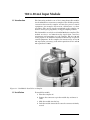
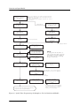
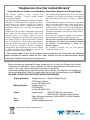
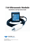
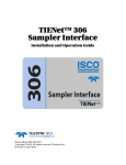
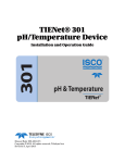
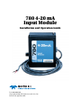
780 4-20 mA
Input Module
Installation and Operation Guide
Part #60-9003-064
Copyright © 1995. All rights reserved, Isco, Inc.
Revision E, April 20, 2011
Foreword
This instruction manual is designed to help you gain a thorough understanding of the
operation of the equipment. Teledyne Isco recommends that you read this manual
completely before placing the equipment in service.
Although Teledyne Isco designs reliability into all equipment, there is always the possibility of a malfunction. This manual may help in diagnosing and repairing the malfunction.
If the problem persists, call or e-mail the Teledyne Isco Technical Service Department
for assistance. Simple difficulties can often be diagnosed over the phone.
If it is necessary to return the equipment to the factory for service, please follow the
shipping instructions provided by the Customer Service Department, including the
use of the Return Authorization Number specified. Be sure to include a note
describing the malfunction. This will aid in the prompt repair and return of the
equipment.
Teledyne Isco welcomes suggestions that would improve the information presented in
this manual or enhance the operation of the equipment itself.
Teledyne Isco is continually improving its products and reserves the right to
change product specifications, replacement parts, schematics, and instructions without notice.
Contact Information
Customer Service
Phone:
(800) 228-4373
(USA, Canada, Mexico)
(402) 464-0231
(Outside North America)
Fax:
(402) 465-3022
Email:
[email protected]
Technical Support
Phone:
Email:
(800) 775-2965
(Analytical)
(866) 298-6174
(Samplers and Flow Meters)
[email protected]
Return equipment to: 4700 Superior Street, Lincoln, NE 68504-1398
Other Correspondence
Mail to:
P.O. Box 82531, Lincoln, NE 68501-2531
Email:
[email protected]
Web site:
www.isco.com
Revised March 17, 2009
780 4-20 mA Input Module
1.1 Introduction
The 780 analog module is one of Isco’s interchangeable modules
for the 6700 Series wastewater samplers. The module provides
connection between the sampler and non-Isco process control
equipment (for example: flow meters, chlorinators, or chart
recorders). The analog signal transmitted to the sampler can
then be used to pace, proportion, or trigger sampling routines.
The 780 module can only be used with 6700 Series samplers. The
module receives a 4 to 20 mA analog signal from a non-Isco
instrument and transmits it to the sampler. The 4 to 20 mA
analog signal is an industrial standard current loop for process
control equipment. In the sampler, the current range of 4 to 20
mA represents percentage, with 4 mA equivalent to 0% and 20
mA equivalent to 100%.
Figure 1-1 780 Module Installed on a Sampler
1.2 Installation
To install the module:
1. Turn the sampler off.
2. Remove the connector cap in the module bay and move it
aside.
3. Slide the module into the bay.
4. Push the module forward to be sure the connector is firmly
seated.
1-1
780 4-20 mA Input Module
Note
The module must be installed on the sampler controller before
the controller is turned on or programmed, and before running
a program that requires a module.
To remove the module, turn the sampler off. Depress the silver
spring button and pull the module from the bay. Do not use the
module’s cord to pull it from the bay. Pulling the cord may
damage the module. Replace the connector cap attached to the
controller.
WARNING
The 780 module has not been approved for use in
hazardous locations as defined by the National Electrical
Code. Before installing any device in a dangerous location,
review the safety precautions in the back of your sampler
manual. Check applicable guidelines, codes, and
regulations of federal, state, city, and county agencies.
1.2.1 Installation Checklist
1. Install the module, then turn the sampler on.
2. Install the non-Isco equipment.
3. Connect the non-Isco equipment to the module (see Wiring
Instructions below).
4. Program the sampler.
5. Set up the sampler (see sampler manual).
6. Run the program.
1.3 Wiring Instructions
The 780 module consists of a case and a 10-foot, non-detachable
cable. The cable ends in a pig tail for splicing to the non-Isco
instrument. The module is a current loop device which is wired
in series with the other instrument. Connect the negative output
of the non-Isco instrument to the module’s black wire and the
positive output to the module’s red wire. The module will only
record accurate measurements if the wire polarity is correct.
1.4 Operation
When a module is installed, the sampler adds the necessary
display screens for programming. These screens appear in Figure
1-2 and Figure 1-3.
You must have the module installed before turning the controller
on. When the controller is turned on, it looks for a module. If the
module is installed after the controller is turned on, you will not
be able to program the sampler to use the module.
The module receives an analog 4-20 mA signal, measures the
current, and sends the reading to the sampler. The sampler then
converts the reading to a percentage. The user selects whether it
will display Level, Flow Rate, or Percentage. When Flow is
1-2
780 4-20 mA Input Module
selected, the current range of 4-20 mA represents flow rate, with
4 mA equivalent to 0% flow and 20 mA equivalent to 100% of the
maximum flow value entered.
For more information about programming, see the Programming
section of the sampler manual.
Note
An asterisk (*) appears next to the flow value if the module was
unable to take a reading. If an asterisk appears, the reading
displayed is the last available reading.
1.4.1 Programmed Enable
When a 4-20 mA module is installed, an additional enable option
is available. Depending on which display option you select, this
option will be LEVEL, FLOW RATE, or PERCENT. For more
information about programming, see Sampler Enable in the
sampler manual.
1.5 Maintenance
The 780 module has no user-serviceable parts. Its case is completely sealed to protect the internal components. To repair the
unit, the case must be broken open and replaced. If you think
your module requires repair, contact the Isco Customer Service
department for information on returning it to the factory.
1.6 Technical
Specifications
Technical specifications for the 780 module are listed in the table
below:
Table 1-1 Technical Specifications for the 780 Analog Module
Weight
1.1 lbs (0.5 kg)
Dimensions
4.9 x 5.7 x 2.0 inches (12.4 x 14.5 x 5.1 cm)
Material
Polystyrene
Operating Temperature
32° to 120° F (0° to 49° C)
Storage Temperature
0° to 140° F (-18° to 60° C)
Enclosure
NEMA 4X, and 6, IP 67
Power
Provided by the sampler.
Memory
Nonvolatile programmable Flash.
Field updatable through the sampler.
Readings
Programmable through sampler at 1, 2, 5, 10, 15, and 30 minute intervals.
Accuracy
± 0.5%
Resolution
± 0.1%
General Notes:
All weights may vary ± 0.2 lb (± 0.1 kg).
All lengths may very ± 1/4 inch (± 0.64 cm).
1-3
780 4-20 mA Input Module
1.6.1 Flash Memory and
Software Upgrades
The 780 module has Flash memory to store its software. With
Flash technology, you can upgrade your module’s software
without sending it back to the factory or replacing the chip.
Simply connect a computer to the sampler with the module
installed and run the Flash Update program.
Note
When updating the Flash memor y, the module must be
attached to the sampler and power must be supplied to the
sampler.
1.6.2 How to Get Help
1-4
Contact information can be found in the Foreword of this
manual.
780 4-20 mA Input Module
This screen appears only when a module has been
changed or if the module was unplugged while the
sampler was powered up.
MODULE INSERTED-DOWNLOAD DATA NOW
OR LOSE ALL DATA!
DONE
Standard
6712
SAMPLER
STANDARD PROGRAMMING
For HELP at any
screen press ? key
Extended
RU N
PROGRAM
VIEW REPORT
OT H E R F U N C T I O N S
SITE DESCRIPTION
“ FA C TO R Y ”
CHANGE?
YES
NO
6712 SAMPLER
EXTENDED PROGRAMMING
Fo r H E L P a t a n y
screen press ? key
RU N “ E X T E N D E D 1 ”
PROGRAM
VIEW REPORT
OT H E R F U N C T I O N S
PROGRAM NAME
“EXTENDED 1”
CHANGE?
YES
NO
See Sampler Manual
See Sampler Manual
SELECT UNITS FOR
LENGTH:
ft
m
SELECT UNITS FOR
FLOW RATE
cfs gps gpm Mgd
lps m3s m3h m3d
N OT E :
To p r o g a
r m the module or
run a program that requires
a module, you must plug in
the module before turning
on the controller.
SELECT UNITS FOR
FLOW VOLUME:
cf gal Mgal
m3 lit
PROGRAM MODULE?
YES
NO
No
Yes
SELECT A 4 - TO - 20 MA
SIGNAL TYPE:
LEVEL FLOW RATE
PERCENT OF MAX
NEW MODULE SETUP-DOWNLOAD DATA NOW
OR LOSE ALL DATA!
DONE
If applicable. This screen appears only when
a selection is changed. Selecting NO will cause the
sampler to not accept the module setup changes.
DATA STORAGE
INTERVAL IN MINUTES
1 2 5
10 15 30
INTERVAL CHANGED-DOWNLOAD DATA NOW
OR LOSE ALL DATA!
DONE
If applicable. This screen appears only when the
interval is changed. If NO is selected, the storage
interval will not change.
Continue with the sampler programming
sequence (see sampler manual)
Figure 1-2 Programming the Sampler to use the 780 4-20 mA Module
1-5
780 4-20 mA Input Module
MODULE INSERTED-DOWNLOAD DATA NOW
OR LOSE ALL DATA!
DONE
This screen appears only when a module has been
changed or if the module was unplugged while the
sampler was powered.
If NO is selected, the sampler responds as if there
is no module.
Standard
6712 SAMPLER
S TA N D A R D P R O G R A M M I N G
For HELP at any
screen press ? key
Extended
RUN
PROGRAM
VIEW REPORT
OTHER FUNCTIONS
SITE DESCRIPTION
“ FAC TO RY ”
6712 SAMPLER
EXTENDED PROGRAMMING
For HELP at any
screen press ? key
RUN “EXTENDED 1”
PROGRAM
VIEW REPORT
OTHER FUNCTIONS
See Sampler Manual
PROGRAM NAME
“EXTENDED 1”
SITE DESCRIPTION
“ FAC TO RY ”
See Sampler Manual
UNITS SELECTED
LENGTH: ft
UNITS SELECTED:
F L O W R AT E : c f s
FLOW VOLUME: Mgal
SELECT UNITS FOR
LENGTH:
ft
m
SELECT UNITS FOR
F L O W R AT E :
cfs gps gpm Mgd
lps m3s m3h m3d
SELECT UNITS FOR
FLOW VOLUME:
cf gal Mgal
m3 lit
4 - TO - 20 mA MODULE
PERCENT OF MAX
SELECT 4-TO-20 mA
SIGNAL TYPE:
LEVEL FLOW RATE
PERCENT OF MAX
NEW MODULE SETUP -DOWNLOAD DATA NOW
OR LOSE ALL DATA!
DONE
NOTE:
To p r o g r a m t h e m o d u l e o r
run a program that requires
a module, you must plug in
the module before turning
on the controller.
FLOW RATE AT 20 mA:
1000 cfs
If appicable. This screen appears
only when a selection is changed.
Selecting NO will cause the sampler
to not accept the module setup changes.
5 MINUTE
DATA INTERVAL
D ATA S T O R A G E
I N T E RVA L I N M I N U T E S :
1
2
5
10
15
30
Continue with the sampler programming
sequence (see sampler manual).
INTERVAL CHANGED -DOWNLOAD DATA NOW
OR LOSE ALL DATA!
DONE
If appicable. This screen appears
only when a selection is changed.
If NO is selected, the storage
interval will not change.
Figure 1-3 Quick View: Programming the Sampler to Use the 780 4-20 mA Module
1-6
Warranty
Teledyne Isco One Year Limited Warranty*
Factory Service for Teledyne Isco Flow Meters, Waste Water Samplers, and Syringe Pumps
This warranty exclusively covers Teledyne Isco
instruments, providing a one-year limited warranty
covering parts and labor.
Any instrument that fails during the warranty period due to
faulty parts or workmanship will be repaired at the factory
at no charge to the customer. Teledyne Isco’s exclusive
liability is limited to repair or replacement of defective
instruments. Teledyne Isco is not liable for consequential
damages.
Teledyne Isco will pay surface transportation charges both
ways within the 48 contiguous United States if the
instrument proves to be defective within 30 days of
shipment. Throughout the remainder of the warranty period,
the customer will pay to return the instrument to Teledyne
Isco, and Teledyne isco will pay surface transportation to
return the repaired instrument to the customer. Teledyne
Isco will not pay air freight or customer’s packing and
crating charges. This warranty does not cover loss, damage,
or defects resulting from transportation between the
customer’s facility and the repair facility.
The warranty for any instrument is the one in effect on date
of shipment. The warranty period begins on the shipping
date, unless Teledyne Isco agrees in writing to a different
date.
Excluded from this warranty are normal wear; expendable
items such as charts, ribbon, lamps, tubing, and glassware;
fittings and wetted parts of valves; and damage due to
corrosion, misuse, accident, or lack of proper maintenance.
This warranty does not cover products not sold under the
Teledyne Isco trademark or for which any other warranty is
specifically stated.
No item may be returned for warranty service without a
return authorization number issued by Teledyne Isco.
This warranty is expressly in lieu of all other warranties
and obligations and Teledyne Isco specifically disclaims
any warranty of merchantability or fitness for a
particular purpose.
The warrantor is Teledyne Isco, Inc. 4700 Superior,
Lincoln, NE 68504, U.S.A.
* This warranty applies to the USA and countries where Teledyne Isco Inc. does not have an authorized
dealer. Customers in countries outside the USA, where Teledyne Isco has an authorized dealer, should
contact their Teledyne Isco dealer for warranty service.
Before returning any instrument for repair, please call, fax, or e-mail the Teledyne Isco Service
Department for instructions. Many problems can often be diagnosed and corrected over the
phone, or by e-mail, without returning the instrument to the factory.
Instruments needing factory repair should be packed carefully, and shipped to the attention of
the service department. Small, non-fragile items can be sent by insured parcel post. PLEASE
BE SURE TO ENCLOSE A NOTE EXPLAINING THE PROBLEM.
Shipping Address:
Mailing Address:
Phone:
Fax:
Email:
Teledyne Isco, Inc. - Attention Repair Service
4700 Superior Street
Lincoln, NE 68504 USA
Teledyne Isco, Inc.
PO Box 82531
Lincoln, NE 68501 USA
Repair service:
(800) 775-2965 (lab instruments)
(866) 298-6174 (samplers & flow meters)
Sales & General Information: (800) 228-4373 (USA & Canada)
(402) 465-3001
[email protected]
March 8, 2011 P/N 60-1002-040 Rev E