1
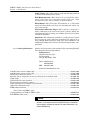
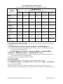
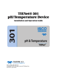
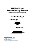
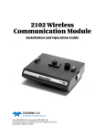
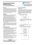
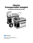
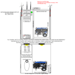
TIENet™ 310 Ultrasonic Level Sensor Installation and Operation Guide Ultrasonic Level Sensor Manual Body #69-4313-010 Copyright © 2012. All rights reserved, Teledyne Isco Revision B, November 5, 2012 Foreword This instruction manual is designed to help you gain a thorough understanding of the operation of the equipment. Teledyne Isco recommends that you read this manual completely before placing the equipment in service. Although Teledyne Isco designs reliability into all equipment, there is always the possibility of a malfunction. This manual may help in diagnosing and repairing the malfunction. If the problem persists, call or e-mail the Teledyne Isco Technical Service Department for assistance. Simple difficulties can often be diagnosed over the phone. If it is necessary to return the equipment to the factory for service, please follow the shipping instructions provided by the Customer Service Department, including the use of the Return Authorization Number specified. Be sure to include a note describing the malfunction. This will aid in the prompt repair and return of the equipment. Teledyne Isco welcomes suggestions that would improve the information presented in this manual or enhance the operation of the equipment itself. Teledyne Isco is continually improving its products and reserves the right to change product specifications, replacement parts, schematics, and instructions without notice. Contact Information Customer Service Phone: (800) 228-4373 (USA, Canada, Mexico) (402) 464-0231 (Outside North America) Fax: (402) 465-3022 Email: [email protected] Technical Support Phone: Email: Toll Free (866) 298-6174 (Samplers and Flow Meters) Toll Free (800) 775-2965 (Syringe Pumps and Liquid Chromatography) [email protected] Return equipment to: 4700 Superior Street, Lincoln, NE 68504-1398 Other Correspondence Mail to: P.O. Box 82531, Lincoln, NE 68501-2531 Email: [email protected] Revised September 2012 TIENet™ 310 Ultrasonic Level Sensor Safety TIENet™ 310 Ultrasonic Level Sensor Safety General Warnings Before installing, operating, or maintaining this equipment, it is imperative that all hazards and preventive measures are fully understood. While specific hazards may vary according to location and application, take heed of the following general warnings: WARNING Avoid hazardous practices! If you use this instrument in any way not specified in this manual, the protection provided by the instrument may be impaired. AVERTISSEMENT Éviter les usages périlleux! Si vous utilisez cet instrument d’une manière autre que celles qui sont specifiées dans ce manuel, la protection fournie de l’instrument peut être affaiblie; cela augmentera votre risque de blessure. Hazard Severity Levels This manual applies Hazard Severity Levels to the safety alerts, These three levels are described in the sample alerts below. CAUTION Cautions identify a potential hazard, which if not avoided, may result in minor or moderate injury. This category can also warn you of unsafe practices, or conditions that may cause property damage. WARNING Warnings identify a potentially hazardous condition, which if not avoided, could result in death or serious injury. DANGER DANGER – limited to the most extreme situations to identify an imminent hazard, which if not avoided, will result in death or serious injury. v TIENet™ 310 Ultrasonic Level Sensor Safety Hazard Symbols The equipment and this manual use symbols used to warn of hazards. The symbols are explained below. Hazard Symbols Warnings and Cautions The exclamation point within the triangle is a warning sign alerting you of important instructions in the instrument’s technical reference manual. The lightning flash and arrowhead within the triangle is a warning sign alerting you of “dangerous voltage” inside the product. Symboles de sécurité Ce symbole signale l’existence d’instructions importantes relatives au produit dans ce manuel. Ce symbole signale la présence d’un danger d’électocution. Warnungen und Vorsichtshinweise Das Ausrufezeichen in Dreieck ist ein Warnzeichen, das Sie darauf aufmerksam macht, daß wichtige Anleitungen zu diesem Handbuch gehören. Der gepfeilte Blitz im Dreieck ist ein Warnzeichen, das Sei vor “gefährlichen Spannungen” im Inneren des Produkts warnt. Advertencias y Precauciones Esta señal le advierte sobre la importancia de las instrucciones del manual que acompañan a este producto. Esta señal alerta sobre la presencia de alto voltaje en el interior del producto. vi TIENet™ Model 310 Ultrasonic Level Sensor Table of Contents Section 1 Introduction 1.1 1.2 1.3 1.4 1.5 Description. . . . . . . . . . . . . . . . . . . . . . . . . . . . . . . . . . . . . . . . . . . . . . . . . . . . . . . . . 310 Sensor Design . . . . . . . . . . . . . . . . . . . . . . . . . . . . . . . . . . . . . . . . . . . . . . . . . . . Operation . . . . . . . . . . . . . . . . . . . . . . . . . . . . . . . . . . . . . . . . . . . . . . . . . . . . . . . . . . Technical Specifications . . . . . . . . . . . . . . . . . . . . . . . . . . . . . . . . . . . . . . . . . . . . . . Accessories . . . . . . . . . . . . . . . . . . . . . . . . . . . . . . . . . . . . . . . . . . . . . . . . . . . . . . . . . 1.5.1 Ordering Information . . . . . . . . . . . . . . . . . . . . . . . . . . . . . . . . . . . . . . . . . . 1-1 1-2 1-2 1-3 1-3 1-4 Section 2 Installation and Setup 2.1 Sensor Installation Considerations . . . . . . . . . . . . . . . . . . . . . . . . . . . . . . . . . . . . . 2-1 2.1.1 Beam Angle . . . . . . . . . . . . . . . . . . . . . . . . . . . . . . . . . . . . . . . . . . . . . . . . . . 2-1 2.1.2 Humidity . . . . . . . . . . . . . . . . . . . . . . . . . . . . . . . . . . . . . . . . . . . . . . . . . . . . 2-1 2.1.3 Surface . . . . . . . . . . . . . . . . . . . . . . . . . . . . . . . . . . . . . . . . . . . . . . . . . . . . . . 2-1 2.1.4 Temperature . . . . . . . . . . . . . . . . . . . . . . . . . . . . . . . . . . . . . . . . . . . . . . . . . 2-1 2.1.5 Waves . . . . . . . . . . . . . . . . . . . . . . . . . . . . . . . . . . . . . . . . . . . . . . . . . . . . . . . 2-2 2.1.6 Wind . . . . . . . . . . . . . . . . . . . . . . . . . . . . . . . . . . . . . . . . . . . . . . . . . . . . . . . . 2-2 2.1.7 Hazardous Locations . . . . . . . . . . . . . . . . . . . . . . . . . . . . . . . . . . . . . . . . . . . 2-2 2.2 Connecting the Cable . . . . . . . . . . . . . . . . . . . . . . . . . . . . . . . . . . . . . . . . . . . . . . . . 2-2 2.3 Sensor Installation . . . . . . . . . . . . . . . . . . . . . . . . . . . . . . . . . . . . . . . . . . . . . . . . . . 2-6 2.3.1 Dead Band . . . . . . . . . . . . . . . . . . . . . . . . . . . . . . . . . . . . . . . . . . . . . . . . . . . 2-6 2.3.2 Submersion and Fouling . . . . . . . . . . . . . . . . . . . . . . . . . . . . . . . . . . . . . . . . 2-6 2.3.3 Mounting Options . . . . . . . . . . . . . . . . . . . . . . . . . . . . . . . . . . . . . . . . . . . . . 2-6 2.4 Installation in Hazardous Locations . . . . . . . . . . . . . . . . . . . . . . . . . . . . . . . . . . . . 2-7 2.4.1 Important Information Regarding “X” Marking . . . . . . . . . . . . . . . . . . . . . 2-8 2.4.2 Electrical Requirements . . . . . . . . . . . . . . . . . . . . . . . . . . . . . . . . . . . . . . . . 2-9 2.4.3 Ambient Environment . . . . . . . . . . . . . . . . . . . . . . . . . . . . . . . . . . . . . . . . . . 2-9 2.5 Configuring the System . . . . . . . . . . . . . . . . . . . . . . . . . . . . . . . . . . . . . . . . . . . . . 2-12 2.5.1 Updating the Device List . . . . . . . . . . . . . . . . . . . . . . . . . . . . . . . . . . . . . . . 2-12 2.5.2 Measurement Setup . . . . . . . . . . . . . . . . . . . . . . . . . . . . . . . . . . . . . . . . . . . 2-14 2.6 Level Calibration. . . . . . . . . . . . . . . . . . . . . . . . . . . . . . . . . . . . . . . . . . . . . . . . . . . 2-15 2.7 Firmware Updates . . . . . . . . . . . . . . . . . . . . . . . . . . . . . . . . . . . . . . . . . . . . . . . . . 2-16 2.8 Contact Teledyne Isco . . . . . . . . . . . . . . . . . . . . . . . . . . . . . . . . . . . . . . . . . . . . . . . 2-16 List of Figures 1-1 Basic Signature monitoring system with 310 (mounting hardware not shown) . . . . . . . . . . . . . . . . . . . . . . . . . . . . . . . . . . . . . . . 1-2 310 Ultrasonic TIENet Sensor . . . . . . . . . . . . . . . . . . . . . . . . . . . . . . . . . . . . . . . . . 2-1 TIENet Device terminal strips . . . . . . . . . . . . . . . . . . . . . . . . . . . . . . . . . . . . . . . . 2-2 Installing cable with a cord-grip fitting . . . . . . . . . . . . . . . . . . . . . . . . . . . . . . . . . 2-3 TIENet Device terminal connections . . . . . . . . . . . . . . . . . . . . . . . . . . . . . . . . . . . 2-4 Attach wired terminal strip to case board socket . . . . . . . . . . . . . . . . . . . . . . . . . . 2-5 Position and secure the cable . . . . . . . . . . . . . . . . . . . . . . . . . . . . . . . . . . . . . . . . . . 2-6 Sensor mounting options . . . . . . . . . . . . . . . . . . . . . . . . . . . . . . . . . . . . . . . . . . . . . 1-1 1-2 2-3 2-3 2-4 2-4 2-5 2-7 vii TIENet™ Model 310 Ultrasonic Level Sensor Table of Contents 2-7 Sensor labeling regarding hazloc installations . . . . . . . . . . . . . . . . . . . . . . . . . . . . 2-9 2-8 Hazardous Location Installation Control Drawing-Atex . . . . . . . . . . . . . . . . . . . 2-10 2-9 Hazardous Location Installation Control Drawing-CSA . . . . . . . . . . . . . . . . . . . 2-11 2-10 Character grid . . . . . . . . . . . . . . . . . . . . . . . . . . . . . . . . . . . . . . . . . . . . . . . . . . . 2-12 2-11 Menu Tree: 310 Configuration . . . . . . . . . . . . . . . . . . . . . . . . . . . . . . . . . . . . . . . 2-13 2-12 Configuring ultrasonic level measurement . . . . . . . . . . . . . . . . . . . . . . . . . . . . . 2-14 2-13 Ultrasonic level adjustment and calibration . . . . . . . . . . . . . . . . . . . . . . . . . . . 2-15 viii TIENet™ Model 310 Ultrasonic Level Sensor Section 1 Introduction The Signature® Flow Meter uses the TIENet™ 310 Device to provide non-contact liquid level measurement. The flow meter has built-in level-to-flow conversions that cover the majority of open channel flow measurement situations. 1.1 Description The ultrasonic sensor is mounted over the flow stream. The flow meter measures the time interval between transmission of a sound pulse from the sensor, and receiving its echo off the surface of the liquid, to determine the level of the stream. Signature Flow Meter 310 TIENet Sensor Figure 1-1 Basic Signature monitoring system with 310 (mounting hardware not shown) 1-1 TIENet™ Model 310 Ultrasonic Level Sensor Section 1 Introduction This non-contact measurement method reduces the frequency of maintenance, and is ideal for applications where the flow may contain chemicals, grease, silt, or suspended solids. 1.2 310 Sensor Design The ultrasonic level sensor consists of a housing with a single transducer that is both pulse transmitter and echo receiver. A temperature sensor within the housing measures the ambient temperature, and a microprocessor automatically compensates for speed-of-sound changes due to any changes in air temperature. The 310 is available with a 10m or 23m cable. For greater distances, external connection via conduit, and connection of additional TIENet devices, the TIENet Expansion Box is available. Bulk TIENet cable may also be used for greater distances. Figure 1-2 310 Ultrasonic TIENet Sensor 1.3 Operation 1-2 The sensor emits multiple ultrasonic pulses per second. Between pulses, the transducer switches from transmitter to receiver. When the transducer receives the echo from the water’s surface, the sound energy is converted into an electrical signal. The signal is then amplified and processed by the Signature flow meter into an “echo-received” signal. The time between the transmitted pulse and the echo-received signal is proportional to the distance between the transducer and the liquid surface. This distance in turn determines the liquid level used to calculate flow. TIENet™ Model 310 Ultrasonic Level Sensor Section 1 Introduction 1.4 Technical Specifications Table 1-1 310 TIENet Device Specificationsa 3.63" x 4" tall (9.1cm x 10.2cm tall) Cable Length 10 or 23 meters standard (32.8 or 75.5ft) standard Mounting Attachment 3 Weight 4 lbs Body Material PVDF Enclosure IP68 when connected and properly sealed with cord-grip fitting. Temperature Range Operating (compensated) Storage Hazardous Locations -22 to 140°F -40 to 158°F -40 to 140°F Sensor Dimensions /4" NPT Pipe thread nipple w/ Conduit lock nut (1.8 kg) (-30 to 60°C) (-40 to 70°C) (-40 to 60°C) Measurement Range Minimum: 1 ft (0.3m) from sensor to liquid surface Maximum: 11 ft (3.3m) from sensor to liquid at minimum level Measurement Accuracy at 72 °F (22 °C) ±0.02ft (0.006m) at 1ft level change or less; ±0.03ft (0.009m) at greater than 1ft level change Temperature Coefficient within compensated range ± 0.0002 x D (m) per degree C ± 0.00011 x D (ft) per degree F (Where D is the distance from the transducer to the liquid surface) Beam Angle 10° Ultrasonic Signal 50KHz Certifications Group II, Category 1G (zone 0), T4 Class I, Division 1 (and Zone 0), T4 a. 5° From center line All specifications are subject to change without notice. 1.5 Accessories Accessories used in sensor installation are briefly described below. Refer to the next section for ordering information. Note Only the Wall Mount Bracket is approved for use in classified hazardous locations. Other accessories must undergo a hazardous location evaluation in order to fulfill safe installation requirements. Spreader Bar – The Spreader Bar is an expandable pipe for suspending equipment inside a manhole. Outward spring pressure secures it against the manhole walls, like a shower curtain rod. Depending on your application, you can then suspend the 310 TIENet Device, or the Signature Flow Meter itself, from the bar. Cable Straightener – The cable straightener is designed for use in installations where the transducer is suspended by its cable only, such as from the Spreader Bar. The straightener helps hold the transducer vertically plumb, thereby stabilizing alignment. 1-3 TIENet™ Model 310 Ultrasonic Level Sensor Section 1 Introduction Cable Clamp – The cable clamp is used with the Spreader Bar to secure the mounting of the sensor. Wall Mount Bracket – This device lets you install the ultrasonic level sensor on a convenient nearby wall over a flow stream, such as the side of a bridge, or other structure. Floor Mount – The Ultrasonic Floor Mount is a collapsible metal stand attached to the floor, for extending the sensor out over a flow stream. Ultrasonic Calibration Target – This option is designed to make calibration of the level sensor more accurate during the installation process by letting you calibrate the level sensor from outside the manhole. Sunshade – The ultrasonic sunshade is a white plastic cap that fits over the top of the ultrasonic transducer. Its purpose is to keep sunlight from heating the body of the level transducer and introducing temperature errors to the internal temperature compensation. 1.5.1 Ordering Information Options and accessories can be purchased by contacting Teledyne Isco’s Customer Service Department. Teledyne Isco Customer Service Dept. P.O. Box 82531 Lincoln, NE 68501 USA Phone: 800 228-4373 402 464-0231 FAX: 402 465-3022 E-mail:[email protected] 310 Ultrasonic sensor w/ 10m cable ........................................................................................ 60-4314-005 310 Ultrasonic sensor w/ 23m cable ........................................................................................ 60-4314-006 Sunshade for ultrasonic sensor ............................................................................................... 60-3004-142 Spreader bar for suspension of sensor or flow meter in manhole shaft ................................ 60-3004-110 Cable clamp .............................................................................................................................. 60-3004-129 Wall bracket for vertical surface.............................................................................................. 60-2443-092 Floor mount for horizontal surfaces ........................................................................................ 60-2004-611 Cable straightener for suspension over stream ...................................................................... 60-3213-061 Ultrasonic calibration target ................................................................................................... 60-3004-143 TIENet Expansion Box ............................................................................................................ 60-4307-023 Kit includes 10ft TIENet cable Cord grip fitting, 3/4" NPT, for TIENet cable........................................................................... 209-0073-12 Bulk TIENet Cable, 23m.......................................................................................................... 60-4303-065 Note Teledyne Isco uses FreeRTOS version 5.4.2 in its TIENet devices. In accordance with the FreeRTOS license, FreeRTOS source code is available on request. For more information, visit www.FreeRTOS.org. 1-4 TIENet™ Model 310 Ultrasonic Level Sensor Section 2 Installation and Setup The Signature Flow Meter does not have to be mounted near the flow stream. You can install the flow meter itself at a convenient, protected location and route the sensor cable to the measurement point. Proper installation of the 310 sensor is critical for accurate measurement. 2.1 Sensor Installation Considerations 2.1.1 Beam Angle Measurement accuracy can be affected by a number of site factors that should be taken into consideration when selecting the location for the sensor. If the sensor cannot obtain a valid reading, an asterisk (*) will appear next to the displayed level, indicating there is an error. The 310 sensor has a 10° beam angle, forming a cone whose apex is the ultrasonic transducer. The sensor can only detect surfaces within this cone. Narrow channels can result in false echoes and incorrect level readings off the walls and sides of the channel. For preventive measures, see Section 2.5.2 Measurement Setup, and the programming steps in Figure 2-13. The beam becomes narrower at shorter distances, which can increase difficulty in detecting the return echo. If the beam is too wide, the sensor may pick up signals from unwanted surfaces, such as the walls of the channel. Sensor elevation is highly specific to the particular site. 2.1.2 Humidity Conditions of extremely high or low humidity can cause detection to occur either earlier or later than under normal conditions. A drop in water level, normally compensated for by the sensor’s interval-based amplifier, may produce errors in echo detection. Additionally, water droplet condensation on the bottom surface of the sensor can cause measurement errors. 2.1.3 Surface Solids, foam, oil, and turbulence can all absorb or weaken the ultrasonic pulses, causing errors in detection. Foam or oil on the surface of the stream can produce false level readings. 2.1.4 Temperature Changes in ambient temperature significantly affect the velocity of sound. If ambient temperature changes rapidly, there may be a delay before the 310’s temperature sensor can activate temperature compensation. If the sensor will be installed outdoors in direct sunlight, use a sunshade to prevent heating of the sensor housing. 2-1 TIENet™ Model 310 Ultrasonic Level Sensor Section 2 Installation and Setup 2.1.5 Waves Waves on the surface of the flow stream can deflect the ultrasonic signal, causing erroneous readings or total loss of signal. The Signature Flow Meter software is able to reject occasional readings that deviate substantially from normal. 2.1.6 Wind Strong winds can significantly reduce the strength of the return echo. Narrow beams can result in the sound being blown away; likewise, greater distances to the flow stream surface are more subject to distortion in strong winds. 2.1.7 Hazardous Locations Installation in classified hazardous locations must meet specific conditions in order to fulfill safety requirements. Installation must be performed only by trained, qualified personnel. Refer to Section 2.4 Installation in Hazardous Locations for complete information. 2.2 Connecting the Cable External TIENet devices such as the 310 are all connected to the Signature flow meter in the same manner, usually using conduit or cord-grip cable fittings. Multiple external TIENet devices can be connected simultaneously. Refer to your Signature flow meter manual for instructions on accessing the instrument’s interior components. WARNING Before proceeding, ensure that the flow meter has been disconnected from mains power. Note The steps that follow include instructions for installing cord-grip fittings. Some applications will use user-supplied 3/4" ID conduit for cable routing. 2-2 TIENet™ Model 310 Ultrasonic Level Sensor Section 2 Installation and Setup 1. Remove one of the 6-position plug-in terminal strip connectors from the case board. Figure 2-1 TIENet Device terminal strips 2. If using a cord-grip fitting, install the cable nut in the appropriate opening on the bottom of the Signature enclosure, securing it to the wall with the lock nut (concave side facing wall). 3. Feed the TIENet device cable end through the sealing nut and seal, and through the cable nut. Lightly tighten the sealing nut, just enough to hold the cable in place while installing the connector. Lock Nut (concave side facing wall) Sealing Nut Cable Nut Seal (color may vary) Figure 2-2 Installing cable with a cord-grip fitting 4. Attach the wire ends to the terminal strip as shown in Figure 2-3, then press the terminal strip back down into its socket on the case board, as shown in Figure 2-4, taking care not to strain any wire connections. Gently tug each wire when finished, to verify secure connection to the screw terminals. 2-3 TIENet™ Model 310 Ultrasonic Level Sensor Section 2 Installation and Setup Note The SHIELD wire is the bare drain emerging from the foil s h i e l d a r o u n d t h e YE L L OW a n d B ROW N w i r e s. T h e BRAID-DRAIN wire is the bare drain emerging from the surrounding braided shield inside the cable jacket. It is not necessary to prevent the two braids from coming into contact with each other. Shield Braid-Drain Figure 2-3 TIENet Device terminal connections 5. Press the terminal strip back down into its socket on the case board, as shown in Figure 2-5, taking care not to strain any wire connections. Figure 2-4 Attach wired terminal strip to case board socket 2-4 TIENet™ Model 310 Ultrasonic Level Sensor Section 2 Installation and Setup 6. Gently tug the cable downward, to remove any slack within the enclosure, taking care not to put any stress on the connection. 7. Tighten the cord grip sealing nut. CAUTION If you are using conduit instead of the cord-grip fitting, the conduit must be sealed to prevent harmful gases and moisture from entering the Signature enclosure. Failure to seal conduit could reduce equipment life. 8. Close the front panel and fasten it shut with the two Phillips screws. Figure 2-5 Position and secure the cable 2-5 TIENet™ Model 310 Ultrasonic Level Sensor Section 2 Installation and Setup 2.3 Sensor Installation The mounting location of the ultrasonic level sensor depends on the type of primary measuring device (such as a weir or flume), and on the method of level-to-flow conversion used. Refer to the Isco Open Channel Flow Measurement Handbook included with your Signature flow meter, or to instructions provided by the manufacturer of the primary device, for detailed information about locating the measuring point. If you intend to measure flow by some other means, such as a gravity flow equation (Manning) or by calibrating a section of the flow channel, you must locate the measuring point based on the hydraulic characteristics of the channel, as well as the level-to-flow conversion method. In most open channel installations where the level may exceed one-half of full pipe, mount the sensor as near as possible to the midpoint between the entrance and exit to measure over the least turbulent flow. 2.3.1 Dead Band Mount the sensor as close as possible to one foot above maximum expected level. The sensor cannot measure within the foot of space directly below it, called the dead band. 2.3.2 Submersion and Fouling Fouling by grease or solids can cause the sensor to malfunction. The sensor is sealed, so unless it was exposed to corrosive substances, temporary accidental submersion should not harm it. Upon retrieval, ensure that the sensor’s surface is clean. Clean the bottom surface very gently with running water and a soft cloth. 2.3.3 Mounting Options The 310 sensor can be mounted over the flow stream in various ways, depending on which method best fits the application. Optional equipment is available from Teledyne Isco for wall, floor, suspension, and horizontal mounting (see Section 1.5 Accessories). The sensor has a 3/4" NPT male pipe thread with a conduit lock nut to connect it to a mounting bracket or cable stiffener. The sensor cable can be routed through user-provided conduit back to the Signature Flow Meter. Regardless of the mounting method you select, always place the sensor over the center of the stream, and always use a circular bubble level for vertical alignment. 2-6 TIENet™ Model 310 Ultrasonic Level Sensor Section 2 Installation and Setup Wall Mount Approved for classified hazardous locations. Floor Stand Not approved for classified hazardous locations. Suspension (cable straightener recommended) Not approved for classified hazardous locations. Figure 2-6 Sensor mounting options 2.4 Installation in Hazardous Locations Read all labels carefully before installing the equipment! The TIENet Model 310 device is ATEX-approved for use in potentially explosive atmospheres when specific conditions are met, as described in this section in reference to “X” Marking. The 310 is Group II, Category 1G equipment for use in gas hazard zones 0, 1, and 2 (European standards), or Class I Division 1 (North American standards). The braid-drain lead depicted in Figure 2-7 Sensor labeling regarding hazloc installations is normally bonded to earth through the Signature connector case terminals or conduit; it is also electrically connected to the anti-static conductive housing of the 310 sensor. Installation must be performed only by trained, qualified personnel. 2-7 TIENet™ Model 310 Ultrasonic Level Sensor Section 2 Installation and Setup Barriers or isolators required for certifiable safe installation are the responsibility of the user. Refer to the control drawings provided in Figures 2-8 and 2-9. Note Only the Wall Mount Bracket is approved for use in classified hazardous locations. Non-Isco hardware must undergo a hazardous location evaluation in order to fulfill safe installation requirements. WARNING The mounting bracket is a potential isolated charge carrier with a conductive path to the cable braid through the anti-static sensor housing. For classified hazardous locations, your installation MUST satisfy earthing requirements. Refer to IEC 60079-14 section 12.2.4 and IEC 60079-11. WARNING Serpentine loop 2.4.1 Important Information Regarding “X” Marking Do not coil the sensor cable; this will form an inductor and create a hazard. The cable should be kept as short as is practical. If necessary, use a serpentine loop (see figure at left) instead. The ATEX labeling on the serial tag of the 310 device includes a number ending in “X.” The X marking indicates that there are specific conditions that must be met in order for the equipment to comply with intrinsic safety requirements. Refer to Figure 2-7 on the following page. These specific conditions are as follows: • The integral cable must be terminated in a manner suitable for the zone of installation. • No additional cable must be added to the sensor during the installation and the sensor integral cable must be connected directly to the terminals of the associated apparatus. • The Li and Ci of the associated apparatus must be negligible. • The physical spacing between the exposed ends of each insulated wire lead, and earth ground and other IS circuits, must be such that the equipment is isolated up to 500V, and to 1500V for non-IS circuitry. 2-8 TIENet™ Model 310 Ultrasonic Level Sensor Section 2 Installation and Setup • The physical spacing between the end of the wire jacketing and the terminal to which a lead is connected must be such that solid foreign objects of 12.5mm and greater shall not be able to fully penetrate. 2.4.2 Electrical Requirements Always refer to the electrical values listed at the bottom of the 310 serial tag when connecting associated apparatus (i.e., power supply, network interface, etc.). This labeling indicates the maximum input voltage (Ui), maximum input current (Ii), and maximum power (Pi) that can be present at the specified terminals without invalidating intrinsic safety. The power supply parameter allowances must exceed maximum internal capacitance (Ci) and either the maximum internal inductance (Li), or the maximum internal inductance-to-resistance ratio (Li/Ri) of the 310 device and integral cable. These parameters are established on the third party certification report and are available by contacting Teledyne Isco. 2.4.3 Ambient Environment Installation in designated hazardous areas must fall within the temperature range of -40 to +60°C, as specified on the serial tag labeling. Temperature range Refer to Section 2.4.1 for important information about ’X’ marking. Ui = Maximum input voltage Ii = Maximum input current No objects of 12.5mm or greater shall penetrate gap. Pi = Maximum power Spacing between bare wires and other wiring, circuitry, and earth ground, shall enable isolation to 500V. Anti-Static Grounding Protection Figure 2-7 Sensor labeling regarding hazloc installations 2-9 TIENet™ Model 310 Ultrasonic Level Sensor Section 2 Installation and Setup Figure 2-8 Hazardous Location Installation Control Drawing-Atex 2-10 TIENet™ Model 310 Ultrasonic Level Sensor Section 2 Installation and Setup Figure 2-9 Hazardous Location Installation Control Drawing-CSA 2-11 TIENet™ Model 310 Ultrasonic Level Sensor Section 2 Installation and Setup 2.5 Configuring the System To configure the Signature flow meter for operation with the TIENet 310 device, press MENU ( ) to access the top menu, and select Hardware Setup. For all TIENet devices including the 310, select Smart Sensor Setup (TIENet). 2.5.1 Updating the Device List When the 310 is physically added to the system, select Perform Scan so that the flow meter detects it. When the scan is complete, the 310 appears in the list of connected devices, ready to be configured with the steps shown in Figure 2-11 on the following page. Note From the Hardware Setup menu, “Configure” refers to defining and selecting the parameters for each connected device. The four parameters that will appear for the 310 device are: 310 Distance – Distance between the bottom of the sensor and the surface of the flow stream. 310 Air Temperature – Temperature of surrounding (ambient) air 310 Level – Level of the flow stream surface 310 Signal – Strength of the return echo The name of any parameter can be customized by highlighting it and pressing Enter ( ) to display the character grid. Navigate the grid using the arrow keys. Select characters with Enter and clear characters with Delete ( ). 310 Distance Done A B O P c d q r @# > ? Cancel C Q e s $ , Figure 2-10 Character grid 2-12 D R f t % . E S g u ^ F T h v & G U i w * H V j x ( I W k y ) J X l z - K L M N Y Z a b m n o p / : ! _ + = < TIENet™ Model 310 Ultrasonic Level Sensor Section 2 Installation and Setup Select Operation 1. Hardware Setup 2. Configure 3. Administration 4. Home Hardware Setup 1. Smart Sensor Setup (TIENet) 2. SDI-12 Setup 3. MODBUS Input Setup 4. MODBUS Output Setup 5. Modem Setup Smart Sensor Setup (TIENet) • Perform Scan • Configure Measurements With initial connection, begin by performing a hardware scan to add the 310. Configure Measurements 1 - XXX XXX Parameter XXX Parameter Press Enter for a list of sensors. Scroll to the 310 and press Enter to select XXX Parameter Configure Measurements Ultrasonic Level Sensor 310 Distance 310 Level 310 Air Temperature 310 Signal Scroll with arrow keys to highlight / select / deselect any displayed parameter or edit its name. Press NEXT to confirm configuration. There may be a slight delay. Smart Sensor Configuration The sensors are being configured. Please wait... Smart Sensor Setup (TIENet) The sensors have been configured. Figure 2-11 Menu Tree: 310 Configuration 2-13 TIENet™ Model 310 Ultrasonic Level Sensor Section 2 Installation and Setup 2.5.2 Measurement Setup From Measurement Setup (Figure 2-12 below), select Level Input Setup to define the measurement range. The Minimum Blanking Distance is the shortest distance from the sensor face (highest expected liquid level). Because of the dead band, this value can never be less than one foot. Depending on the elevation of your sensor, this value may be increased to help ensure that echoes read by the flow meter come only from the surface of the flow stream, and not off the walls or sides of the channel. The Maximum Blanking Distance is the distance between the sensor face and the bottom of the channel, or zero level. You can enter a slightly larger value than calculated, if you prefer. Dead Band Maximum Blanking Minimum Blanking Configure Options 1. Site Setup 2. Measurement Setup 3. Adjust 4. Equation/Trigger Setup 5. Data Storage/Push Setup 6. Sampler Setup 7. Outputs/Alarms Setup 8. Reset Totalizers 9. Reports/History Setup Measurement Setup 1. Level Input Setup 2. Flow Input Setup 3. Volume Input Setup 1. Level Input Setup 1. 310 Level 310 Level Distance from sensor face to maximum expected liquid level LEVEL Blanking Distance Minimum: Blanking Distance 0 ft Maximum: 3 ft Distance from sensor face to bottom of channel Press Next 2x. Figure 2-12 Configuring ultrasonic level measurement 2-14 TIENet™ Model 310 Ultrasonic Level Sensor Section 2 Installation and Setup 2.6 Level Calibration D – d = h (level) d D Although all other programming steps can be performed off-site, level must be set at the measurement site following installation, at ambient temperature. Once the sensor is installed over the flow stream, measure the present liquid level (see figure at left) and enter this value for Level, under Adjust Options. Then highlight “Adjust” and press Enter to confirm. From this screen, you can also update the display to show the current level of the stream. h Configure Options 1. Site Setup 5. Data Storage/Push Setup 2. Measurement Setup 3. Adjust 6. Sampler Setup 4. Equation/Trigger Setup 7. Outputs/Alarms Setup 8. Reset Totalizers 9. Reports/History Setup Adjust 1. Level Adjust Level 1. 310 Level 310 Level LEVEL ADJUSTMENT ft Level: Last reading: X.XXX ft Time of last adjustment: MM/DD/YYYY TT:TT:TT Adjust Update Reset/calibrate level Display current real-time level Figure 2-13 Ultrasonic level adjustment and calibration 2-15 TIENet™ Model 310 Ultrasonic Level Sensor Section 2 Installation and Setup 2.7 Firmware Updates The TIENet device’s firmware is updated via the USB port on the front panel of the Signature Flow Meter. Step-by-step instructions for updating the firmware can be found in Section 2 of the Signature user manual. 2.8 Contact Teledyne Isco If you have further questions about the installation, operation, and maintenance of your TIENet device, please contact our service department at: Teledyne Isco 4700 Superior St. Lincoln, NE 68504 Phone: 866 298-6174 or 402 464-0231 Fax: 402 465-3022 E-mail: [email protected] 2-16 Compliance Statements ℶ❐₼㦘㹡㦘⹂䓸德㒥⏒侯䤓⚜䱿♙⚺摞 Name and amount of Hazardous Substances or Elements in the product 捷ↅ⚜䱿 Component Name 㦘㹡㦘⹂䓸德㒥⏒侯 Hazardous Substances or Elements 㻭 (Hg) 柘 (Cd) ⏼ↆ杻 (Cr(VI)) ⮩䅃勣啾 (PBB) ⮩䅃ℛ勣啾 (PBDE) 兎恾㨎 Circuit Boards X O O O O O 㣍䯉 Display X O O O O O 㘴兎 Wiring O O O O O X ␔捷䟄冕 Internal Cables O O O O O X 䦃㿐䟄㧉 DC Motor X O O O O X 㘴⯃ Connectors O O X O O O 䟄㻯 Battery X 䟄䭐梏 Solenoid valve X D ec la ra ti o n of C on fo rm ity 杔 (Pb) X O O O O O O O X C E X ℶ❐₼㦘㹡㦘⹂䓸德㒥⏒侯䤓⚜䱿♙⚺摞᧶Name and amount of Hazardous Substances or Elements in the product O: 嫷䯉年㦘㹡㦘⹂䓸德⦷年捷ↅ㓏㦘⧖德㧟㠨₼䤓⚺摞⧖⦷ST/ 㪖屓⸩䤓棟摞尐㻑ⅴₚᇭ O: Represent the concentration of the hazardous substance in this component’s any homogeneous pieces is lower than the ST/ standard limitation. X᧶嫷䯉年㦘㹡㦘⹂䓸德咂⺠⦷年捷ↅ䤓㩟⧖德㧟㠨₼䤓⚺摞怔⒉ST/ 㪖屓⸩䤓棟摞尐㻑ᇭ (←₩♾⦷㷳⮓᧨㫈㗽⸭棔㍔⑄⺈ₙ嫷₼㓢“X” 䤓㔏㦾☮⥯扪嫛扪㷴広㢝ᇭ) X: Represent the concentration of the hazardous substance in this component’s at least one homogeneous piece is higher than the ST/ standard limitation. (Manufacturer may give technical reasons to the “X”marks) 䘾≬∎䞷㦮䟀兞洛䫽⸩ᇭ The Environmentally Friendly Use Period (EFUP) was determined through experience. 䞮ℶ㡴㦮嬺冥䪐⦷侊⒦⚆䪐₼ᇭⓜₘ⇜㟿ⷦ䞮ℶ(207 ⅲ嫷 2007 ) ᇭ椞⚝䤓₹ⷦ㹜ⅲ嫷㦗᧶ A 㦗᧨B ℛ㦗᧨䷘䷘ᇭ The date of Manufacture is in code within the serial number. The first three numbers are the year of manufacture (207 is year 2007) followed by a letter for the month. "A" is January, "B" is February and so on. Hazmat Table Signature Meter, Sensors and Accessories 60-4302-091 Rev.A DECLARATION OF CONFORMITY Trade Name/Model No: Year of Issue: Equipment for Light Industrial/Commercial Environments: The device is an ultrasonic transmitter/receiver using reflected impulses from water surfaces to calculate its depth. It is cable connected to flow monitoring instruments and consists of several circuit board assemblies inside a plastic enclosure. The device is intended for safe operation in an ambient temperature range of -40 to +60 C. 310 Ultrasonic Sensor fo rm ity Equipment Type/Environment: Teledyne Isco 4700 Superior, Lincoln, Nebraska 68504 USA Mailing Address: P.O. Box 82531, Lincoln, NE 68501 on Manufacturer's Name: Manufacturer's Address: 2004/108/EC-The EMC Directive 2006/95/EC- The Low Voltage Directive 94/9/EC - The ATEX Directive of C Application of Council Directive: 2011 II 1G Ex ia IIB T4 Ga (-40C < Ta < +60C) IP68 (self-certified; submerged 9 meters for 72 hours) Notified Body for EC-Type Examination: Baseefa 1180 Buxton UK Model Type 310 Ultra Sonic Sensor: Baseffa11ATEX0180X Issued December 8, 2011 C E EC-type Examination Certificate: D ec la ra t io n Provisions of the Directive fulfilled by the Equipment: Notified Body for Production: Harmonized Safety Standards: Other Harmonized Standards and Specifications used: Baseefa 1180 Buxton UK EN60079-0:2009, EN60079-11:2007 EN 61326-1998 - EMC Requirements for Electrical Equipment for Measurement, Control, and Laboratory Use EN60529:1992 - Degrees of Protection Provided by Enclosure; IP-68 I, the undersigned, hereby declare that the design of the equipment specified above conforms to the above Directive(s) and Standards as of December 20, 2011. USA Representative: ________________________________________ Vikas V. Padhye Ph.D. Vice President and General Manager Teledyne Isco Inc. 4700 Superior Street Lincoln, Nebraska 68504 Phone: (402)-464-0231 FAX: (402)-464-0318 60-4312-011 Warranty Teledyne Isco One Year Limited Factory Service Warranty* This warranty exclusively covers Teledyne Isco instruments, providing a one-year limited warranty covering parts and labor. Any instrument that fails during the warranty period due to faulty parts or workmanship will be repaired at the factory at no charge to the customer. Teledyne Isco’s exclusive liability is limited to repair or replacement of defective instruments. Teledyne Isco is not liable for consequential damages. Teledyne Isco will pay surface transportation charges both ways within the 48 contiguous United States if the instrument proves to be defective within 30 days of shipment. Throughout the remainder of the warranty period, the customer will pay to return the instrument to Teledyne Isco, and Teledyne Isco will pay surface transportation to return the repaired instrument to the customer. Teledyne Isco will not pay air freight or customer’s packing and crating charges. This warranty does not cover loss, damage, or defects resulting from transportation between the customer’s facility and the repair facility. The warranty for any instrument is the one in effect on date of shipment. The warranty period begins on the shipping date, unless Teledyne Isco agrees in writing to a different date. Excluded from this warranty are normal wear; expendable items such as charts, ribbon, lamps, tubing, and glassware; fittings and wetted parts of valves; and damage due to corrosion, misuse, accident, or lack of proper maintenance. This warranty does not cover products not sold under the Teledyne Isco trademark or for which any other warranty is specifically stated. No item may be returned for warranty service without a return authorization number issued by Teledyne Isco. This warranty is expressly in lieu of all other warranties and obligations and Teledyne Isco specifically disclaims any warranty of merchantability or fitness for a particular purpose. The warrantor is Teledyne Isco, 4700 Superior, Lincoln, NE 68504, U.S.A. * This warranty applies to the USA and countries where Teledyne Isco does not have an authorized dealer. Customers in countries outside the USA, where Teledyne Isco has an authorized dealer, should contact their Teledyne Isco dealer for warranty service. Before returning any instrument for repair, please call, fax, or e-mail the Teledyne Isco Service Department for instructions. Many problems can often be diagnosed and corrected over the phone, or by e-mail, without returning the instrument to the factory. Instruments needing factory repair should be packed carefully, and shipped to the attention of the service department. Small, non-fragile items can be sent by insured parcel post. PLEASE BE SURE TO ENCLOSE A NOTE EXPLAINING THE PROBLEM. Shipping Address: Mailing Address: Phone: Fax: Email: Teledyne Isco - Attention Repair Service 4700 Superior Street Lincoln, NE 68504 USA Teledyne Isco PO Box 82531 Lincoln, NE 68501 USA Repair service: (800) 775-2965 (lab instruments) (866) 298-6174 (samplers & flow meters) Sales & General Information: (800) 228-4373 (USA & Canada) (402) 465-3001 [email protected] February 28, 2012 P/N 60-1002-040 Rev G