1
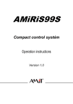
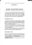
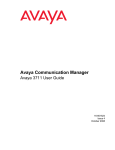
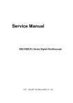
Model 228A Voltage/Current
All references
to the Model
01985,
228 apply
Source
also to the Model
Keithley Instruments, Inc.
All rights reserved.
Cleveland, Ohio, U.S.A.
Document Number: 228A.904.01
228A
WARRANTY
Keithley Instruments, Inc. warrants this product to be fox from defects in ma&al
from date of shipment.
Keithley Instruments, Inc. warrants the following
batteries, diskettes, and documentation.
and workmanship for a period of I year
items for 90 days from the date of shipment: probes, cables, rechargeable
During the warranty period, we will, at our option, either repair or replace any product that proves to be defective,
To exercise this warranty, write or call your local Keithley representative, or contact Keithley headquarters in Cleveland, Ohio.
You will be given prompt assistance and return instructions. Send the product, transportation prepaid, to the indicated service
facility. Repairs will be made and the product returned, transportation prepaid. Repaired or replaced products are warranted for
the balance of the original warranty period, or at least 90 days.
LIMITATION
OF WARRANTY
This warranty does not apply to defects resulting from product modification without,Keithley’s express written consent, or
misuse of any product or part. This warranty also does not apply to fuses, software, non-rechargeable batteries, damage from
battery leakage, or problems arising from normal wear or failure to follow instructions.
THIS WARRANTY IS IN LIEU OF ALL OTHER WARRANTIES, EXPRESSED OR IMPLIED, INCLUDING ANY
IMPLIED WARRANTY OF MERCHANTABILITY
OR FITNESS FOR A PARTICULAR USE. THE REMEDIES PROVIDED HEREIN ARE BUYER’S SOLE AND EXCLUSIVE REMEDIES.
NEITHER KEITHLEY INSTRUMENTS, INC. NOR ANY OF ITS EMPLOYEES SHALL BE LIABLE FOR ANY DIRECT,
INDIRECT, SPECIAL, INCIDENTAL
OR CONSEQUENTIAL
DAMAGES ARISING OUT OF THE USE OF ITS
INSTRUMENTS AND SOFTWARE EVEN IF KEITHLEY INSTRUMENTS, INC., HAS BEEN ADVISED IN ADVANCE
OF THE POSSIBILITY OF SUCH DAMAGES. SUCH EXCLUDED DAMAGES SHALL INCLUDE, BUT ARE NOT LIMITED TO: COSTS OF REMOVAL AND INSTALLATION, LOSSES SUSTAINED AS THE RESULT OF INJURY TO ANY
PERSON, OR DAMAGE TO PROPERTY.
Safety Precautions
The following
safety precautions should be observed before using
[his product and any associated instrumeniarion.
Although some instmmen~s and accessories would normally be used with non-hazardous voltages. rhere are situations where hazardous conditions
may be present.
This product is intended for use by qualified personnel who recognize shock hazards and are familiar with the safety precaurions required to avoid possible injury Read the operating information
carefully before using the product.
The types of product users are:
Responsible body is Ihe individual or group responsible for the use
and maintenance of equipment, for ensuring rhat the equipment IS
operared within its specifications
and operating limits. and for ensurin~ rhat operators are adequately trained.
Operators use the product for its intended function. They must be
trained in electrical safety procedures and proper use of the instilln,ent. They must be protected from electric shock and contact with
hazardous live circuits.
Maintenance
personnel perform routine procedures on the product
to keep it operating, for example, setting the line voltage or replacing consumable materials. Maintenance procedures are described in
the manual. The procedures explicitly state if the operator may Peru
form them. Otherwise, they should be performed only by service
personnel.
Service personnel are trained to work on live circuits, and perform
safe installations and repairs of products. Only properly trained service personnel may perform installation and service procedures.
Exercise extreme caution when a shock hazard is present. Lethal
voltage may be present on cable connector jacks or test fixtures. The
Am&an
Xational Standards Institute (ANSI) states that a shock
hazard exists when vo,,age levels grearer than 30V RMS. 42.4V
peak, or 60VDC are present. A good safety practice is to expect
that hazardous voltage is present in any unknown circuit before
measuring.
Users of this product must be pnxecred from e,cc,ric shock at all
times. The responsible body must ensure lhar users are prevenred
access and/or insulated from every connection point. In some cases.
connections musk be exposed 10 polenrial human contacI. Producl
users in these circumsmnces must be rained IO protect themselves
irom the risk of electric shock. If the circuit is capable of operatins
BI or above 1000 VOIIS. no conductive
part of the circuit may be
exposed.
As described in rhe
(IEC) Standard IEC
(e.g.. Keithley Models
Inslallation Category
Installation Category
International
Eleclrotechnical
Commission
664. digital multimeter
measuting circuits
I75A, 199. 2000,200l.
2002, and 2010) are
II. A,, orher i”strume”,s’
s;gnaI lerminals are
I and must nor be connected to mains.
Do not connect switching cards direcdy 10 unlimited power circuits~
They are intended to be used with impedance limited sources.
NEVER connect swiiching cards directly 10 AC mains. When connecting sources to switching cards. install protective devices 10 limit fault currem and voltage to rhe card.
Before operating an ins,rumen,. make sure rhe line cord is connccted to a properly grounded power receptacle. lnrpcct the connccim~
cables, test leads. and jumpers for possible wear. cracks. or breaks
before each use.
For maximum safety, do not touch the product, test cables. or an)
orher instruments while power is applied IO the circuil under :es,.
ALWAYS remove power from ihe entire lest system and discharge
any capacitors before: connccring or disconnecting cables or jumpers, installing or removing switching
cards. or making imemal
changes, such as installing or removmg]umpers.
Do not louch
common side
Always make
dry. insulated
measured.
any objea rhat could provide a currcm path to the
of the circuit under rest or power line (earth) sround.
measurements wirh dry hands while rrandinp on a
surface capable of wirhstanding
[he voltage being
The instrument and accessories must be used in accordance with its
specifications and operating instructions or the safety of the equipment may be impaired.
The WARNING
heading in a manual explains dangers that might
result in personal injury or death. Always read the associated information very carefully before performing the indicated procedure.
Do not exceed the maximum signal levels of the instruments and accessorics, as defined in the specifications
and operating information, and as shown on the instrument or test fixture panels, or
switching card.
The CAUTION
heading in a manual explains hazards that could
damage the instrument. Such damage may invalidate the warranty.
When fuses are used in a product, replace with same rype and rating
for continued protection against fire hazaid.
Before performing
all test cables.
Chassis connections must only be used as shield connections
measuring circuits, NOT as safety earth ground connections.
for
If you are using a rest fixture. keep the lid closed while power is applied to the device under test. Safe operation requires the use of a
lid interlock.
lfa 0, mew is present, connect it to safety earth ground using the
wire recommended in the user documentation.
The h
symbol on an instrument indicates that the user should refer to the operaring instructions located in the manual.
Then
symbol on an instrument shows that it can source or measure 1000 volts or more. including the combined effect of normal
and common mode voltages. Use standard safety precautions IO
avoid personal contact with these voltages.
Insrmmentation
and accessories
shall not be connected
any maintenance,
disconnect
to humans.
the line cord and
To maintain protection from electric shock and fire, replacement
components in mains circuils, including the power transformer, test
leads, and input jacks, must be purchased from Keithley lnstrumerits. Standard fuses, with applicable national safely approvals,
may be used if the rating and type are the same. Other componenrs
that are not safety related may be purchased from other suppliers as
long as they are equivalent to the original component. (Note that selected pans should be purchased only through Keithley Instruments
to maintain accuracy and functionality
of the product.) If you are
unsure about the applicability
of a replacement component, call a
Keithley instruments office for information.
To clean an instrument, use a damp cloth or mild, water based
cleaner. Clean the exterior of the instrument only. Do not apply
cleaner directly to [he instrument or allow liquids to enter or spill
on the instrument. Products that consist of a circuit board with no
case or chassis (e.g., data acquisition board for installation
inm a
computer) should never require cleaning if handled according to instructions. If the board becomes contaminated and operation is affected, the board should be returned to the factory for proper
cleaning/servicing.
Rev. 10199
CHAPTER
1
Introduction
This booklet has been written to help the user understand the operation and specifications
of the Model 228 Voltage/Current
Source. The chapters in this booklet have been written
to aid the user in some applications. Terms relating to the V/I source such as: stability, line
regulation, load regulation and sensing are defined in the glossary. For a complete explanation of the instrument including front panel controls and IEEE-468 bus operation refer to
the Model 228 Instruction Manual (Document Number 228-901-01).
The Model 228 is a power supply that can source OT sink electrical power. These unique
features set it apart from ordinary power supplies. Actually, because of the Model 228’s
precision and wide dynamic range, the term SOURCE is used to differentiate it from ordinary power supplies. Most power supplies do what the name implies they supply powerusually voltage or current. The Model 228 is capable of precise control of voltage or current
while sourcing or sinking power.
In general, instruments that are defined as power sources supply electrical power to a connected load. Some power sources can also act as a load for a” external source. This is generally
known as sinking power. There are numerous applications for a” instrument that can sink
power as well as supply power. For example, the Model 228 can charge then discharge a
battery at a controlled rate.
There are three features that differentiate
1. Multiple Ranges
2. Four Quadrant Operation
3. Constant Voltage/Co”sta”t
Current
the Model
228 from power supplies:
Glossary
Accuracy-Accuracy
is defined as how close the actual output value reflects the programmed
value. Display monitor accuracy is defined as how close the display monitor reflects
the actual output value.
Auto Cal-The A/D converter in the Model 228 measures various gains and offsets within
the instrument. With this information,
the microprocessor calculates calibration factors which it uses when programming the output. Power on, Program 6 and Program
9 all start the Auto Cal sequence.
Battery Back Up-Values programmed into the 100 step memory are saved even when the
AC power is turned off. This is possible because the values are stored in CMOS memory
which is powered by a rechargeable battery.
Common Mode Voltage-Common
mode voltage is the potential difference between
“earth ground and normally common” output terminal of the Model 228. This voltage
is normally generated when connecting two power supplies in series.
Compliance-Compliance
is defined as the extent to which an output parameter (voltage
or current) deviates from the programmed value without compromise of the output
parameter. e.g. For constant voltage operation, current control yields to voltage control
as long as the actual output current is within the range of +ISE~ING (the programmed setting) to -IsETTING (the compliance setting). Outside this range, the current
control circuit attempts to take control of the output away from the voltage control circuit.
Constant Voltage/Current-A
constant current source can force current through a device
under test almost independently
of the load resistance. A constant voltage source can
deliver a voltage across a device almost independently
of the load resistance.
Current Monitor-The
Model 228 output current is sensed internally and converted to the
*lV full scale voltage. This voltage is routed to the A/D converter and circuitry but,
also is available to the user via the current monitor output terminals.
Dwell Time-Dwell
time is the time spent on a specific memory location. Dwell time is used
in the Single Step, Single Cycle and Continuous memory control modes. The range
of dwell time is 20msec to 1000sec.
Floating-Floating
is the term used to describe a condition where a common mode voltage
exists between earth ground and the instrument or conductor of interest.
Four Quadrant Operation-In
four quadrant operation, voltage or current can be either
positive or negative thus, four combinations are possible. Positive polarity of voltage
and current is defined as “source quadrants”, where power is delivered from the Model
228 to the user’s load. Opposite polarity of voltage and current (+V, -I) or (-V, +I) is defined as “sink quadrants”, where power from the user is dissipated in the Model 228.
Impedance-The
effect of R, L, or C in series or parallel with the output. This causes the
output voltage or current to vary slightly when load changes occur.
Load-The device to which power is delivered.
Load Line-The load line is the operating line on the V vs I graph for a particular load.
Load Regulation-Load
regulation is the ability of the Model 228 to keep the output voltage
or current constant when the load changes.
Modulation (External)-External
modulation is a low frequency (DC to 600H.z) low voltage
(rlOV) signal that is supplied by the user and is superimposed on the output signal
of the Model 228.
2
Operate-Operate
programs the output to the user selected values. Standby programs the
output to OV, OA. During operate, the two displays show actual measured values of
voltage and current. During standby, the programmed settings are displayed.
Quick Disconnect Board-An
output board that contains the OUTPUT, SENSE, EXTERNAL
MODULATION
and CURRENT MONITOR terminals. This board fits into the recessed slot on the rear panel of the Model 228.
Response Time-Response
time is the time the Model 228 microprocessor takes to respond
to a signal on the External Trigger input. Response time is measured from trigger input until the output has change 99% of the difference between the old memory step
and the new memory step. A range change, polarity change or change between voltage
and current extends the response time.
Self Test-During
the power on sequence the Model 228 tests memory (RAM and ROM),
the AID converter control circuitry and power supplies. During operation, the Model
228 monitors temperatures,
power supplies and the AID converter. If an error is
discovered, the Model 228 attempts to protect the user and itself.
Sense (Local and Remote)-Remote
sensing maintains regulation at the load instead of the
output terminals of the Model 228 therefore, compensating for the test leads IR voltage
drop. Local sensing maintains regulation at the output terminals of the Model 228.
Source (Vice Sink-Source
is a condition where in the Model 228 delivers power to the user’s
load.
Stability-Stability
is the ability to keep from changing.
Trigger IN & OUT-The
TRIGGER IN and TRIGGER OUT connectors are female BNC connectors that accept or output a negative going greater than 10~s~ TTL pulse. The trigger
input pulse starts the memory control mode. The trigger output pulse appears at the
TRIGGER OUT connector at the end of each programmed dwell time.
Standby (Vice Operate)-The
standby mode programs the Model 228 to output OV, OA and
displays the programmed settings instead of the actual values. Polarity and range
changes are delayed until the OPERATE button is pressed. Modulation
is disabled
in the standby mode.
Sink (Vice Source)-Sink
is described as the ability of the Model 228 to dissipate power supplied by the user’s circuit. This includes discharging batteries, inductive loads and
capacitive loads.
Sink Only-Sink
only reduces internal dissipation so that a full 1OOW can be dissipated by
the Model 228 for long periods of time, even at high ambient temperatures, with no
derating. Since this function reduces the Model 228’s sourcing capability (= 1.5A) it
should only be used when sourcing is not required.
3
CHAPTER
2
Safety Precautions
The following information outlines general safety precautions that should be observed before,
during and after operating the Model 228.
1. Before operation, ground the Model 228 through a properly earth grounded receptacle.
Failure to ground the instrument may result in severe injury or death in the event of
a short circuit or malfunction.
2. Never assume the output is at a safe potential while the AC line is connected.
3. Never come into contact with the output connections while the instrument is turned on.
4. Always set up the test circuit while power is turned off. Do not come into contact with
any part of the test circuit while power is on.
5. Always place the instrument in standby after the measurement or test is complete.
6. Use cables for the output that have appropriate current and insulation rating. For example, if 1OV at 10A is to be produced, or dissipated, then the cables must be rated for
that amount. Also, use insulated lugs for connections on the quick disconnect board.
7. The Model 228 is capable of producing several times its current rating for short periods
of time. Keep this in mind when choosing a load. Brief bursts of high current are still
enough to damage other inskumentation
and cause serious injury.
8. Do not operate the Model 228 with the top and/or bottom covers removed. Lethal potentials are present throughout the mainframe. The covers must also be in place to allow
proper air flow through the instrument. Proper air flow is required to cool the instrument during operation. If proper cooling is impeded the instrument may overheat.
9. When connecting active circuits, observe proper polarity (sink mode). A reversed polarity
may allow the instrument to operate at the current limit of the output fuse (20A).
10. When using the Model 228 to sink power from an external source refer to the example
program and Program 2 (Sink) in Section 3 of the Model 228 Instruction Manual.
11. The MODULATIONand the I MONITORterminals on the quick disconnect board
are electrically shorted.
12. The OUT- terminal is at a potential similar to the MODULATION
and I MONlTOR
terminals. Shorting the OUT terminal to the MODULATION
and/or I MONITOR terminals shorts the Model 228’s current limiting circuitry. The current limiting circuitry
will not function properly if the terminals are shorted. Grounded equipment can cause
this problem.
Example: A grounded function generator connected to the modulation input of the Model
228 with a grounded oscilloscope connected across the output terminals of the Model 228.
13. When using multiple Model 228’s do not connect the modulation inputs together or the
current monitor outputs. Remember, that the OUT- terminals and these other terminals
are at similar potentials.
5
CHAPTER
3
Operating Considerations
General Specifications
For detailed Model 228 specifications
the Table of Contents.
refer to the instruction
Output
manual. Specifications
& Compliance
precede
Accuracy
Accuracy is defined as the degree of uncertainty of a measure to a standard or true value.
There are two accuracy specifications to take into consideration when using the Model 228:
compliance accuracy and output accuracy. These two specifications are described in the
following paragraphs.
Output accuracy refers to the programmed parameters of the Model 228. The programmed
parameters are the values set for voltage and current. These values are set by the user either
by the use of front panel controls or over the IEEE-488 bus. Output accuracy is in effect
when the load does not cause the output to exceed the values of voltage and current set
by the user. For example, if the Model 228 is set for 5V, IA, a resistive load of lOs2 draws
lOOmA from the Model 228. In the operate mode, the front panel display monitor shows
5.OOV and .lOOA. In this case the programmed parameters were not exceeded. Therefore,
the output accuracy is in effect.
Compliance accuracy is in effect when the Model 228 is in the sink mode. The sink mode
occurs whenever the monitored voltage and current are of opposite polarity. For example,
if the Model 228 is set for 5V, 1A a 1OV battery connected to the output terminals (OUT+
connected to the positive of the battery, OUT- connected to the negative of the battery)
forces the output of the Model 228 to + lOV, -lA. In this example the compliance accuracy
becomes effective on current. If the battery is connected across the output terminals with
reverse polarity (OUT+ connected to negative of battery, OUT- connected to positive of
battery) the Model 228 would be in voltage limit instead of current limit.
CAUTION
Observe proper polarity when connecting active circuits such as
batteries and power supplies to the Model 228.
The stated accuracy specifications for output accuracy and compliance accuracy pertain to
the source mode and sink mode respectively. The output accuracy applies while sourcing
power from the Model 228. The compliance accuracy applies while sinking power to the
Model 228.
Display
Monitor
Accuracy
Accuracy refers to the output of the Model 228. The output value could differ from the programmed value by the specified accuracy. The displayed value could differ from the output
value by the specified accuracy.
The displayed readback of the output is approximately
2’S times per second. The programmed output is fast but has some inherent offset. For steady output the display value
is more accurate than the programmed setting. For changing output, the programmed setting is precise while the displayed value requires sufficient time to assme steady state.
For example, if the output is programmed for l.OOOV with no load, the output will be l.OOOV
i2mV. If the output is l.OOOV, the display will read 1.000 *ZmV.
Programmin g time is stated as 30msec maximum from trigger to 99% of programmed change.
For example, if 15V is present at the output and the instrument is programmed for 5OV,
it will take the Model 228 30msec to reach 49.6V. This specification applies when on the
same range, and polarity. Time is measured from external input to settled output.
Load transient recovery time is specified with a resistive load only. With a resistive load,
the output can recover 90% of any load changes within lmsec after the end of the changes.
This time is specified for the changes which do not cause transfer to another control mode.
(i.e. voltage to current limit, or source to sink).
“SETTING
1
2 kETTlNG
1OOsH
OUT i
1 OOpR
,lO” RANGEl
VSETTING
“SETTING
OUT -
Figure
1. Model
228
Equivalent
Output
Circuit
9
The Model 228 is a constant current voltage/constant
current source. The load determines
the mode of the Model 228, either constant voltage or constant current. For example, if the
load is of high impedance, the Model 228 is in the constant voltage mode with the load
resistance determining the current mode. If the load is of low impedance, the Model 228
is in the constant current mode with the load resistor determining the voltage. For example, if the Model 228 is programmed to 1OV and lOA, a load of more than 10 controls the
current. A load of less than IQ controls the voltage.
1 = lOVi2n = 5A (2Q load, requires 5A)
V = 10A x 0.5Q = 5V (0.5~7 load, requires 5A)
The preceding
paragraph
can be summarized
as follows:
V228 setting
R>
then, the Model 228 operates as a constant
voltage source.
then, the Model 228 operates as a constant
current
1228 setting
V22gsetting
R<
source
1~8 Setting
Where:
V = The voltage setting on the Model 228
I = The current setting on the Model 228.
R = Connected load.
Figure 2 shows the Model 228 using a resistive load line. Figure 3 shows the general graph
of operation for the Model 228.
10
V @ ZERO CURRENT
I @ ZERO VOLTAGE
-1
Figure
2. Model
228
with
Resistive
Load Line
1
+v
A
H
c
A
B
C
D
E
F
=
=
=
=
=
=
+,,S”
(DESTRUCTIVE LIMIT1
-CURRENT L,M,T (+PROGRAMMED,
+“OLTAGE LIMIT ,+PRDGRAMMED)
+CURRENT LIMIT ,+PROGRAMMEDl
-VOLTAGE LIMIT (+PROGRAMMEDl
2DA FUSE
c: -.._ ^ 9 II-,...*
G =
H =
I =
J =
K =
L =
-
F
-LG
1
-115 (DESTRUCTIVE LIMIT)
+C”RRENT
LlMlT ,-PROGRAMMED,
-VOLTAGE LIMIT t-PROGRAMMED1
-CURRENT LIMIT I-PROGRAMMED)
+“DLTAGE LIMIT I-PROGRAMMED1
2DA FUSE
n-n.,*:,..
Sensing (Remote and Local)
The sense (S+ and S-) terminals are located on the quick disconnect board. The sense terminals are used in the volts mode. When a load is connected to the Model 228, there is
an IR lead drop between the load and the Model 228.
CAUTION
Take care to connect the sense terminals (S+ and S-) to the load
with proper polarity. Connect S + to the positive terminal and
S - to fhe negative terminal. Improper polarity may result in
damage to the instrument
and load.
The effects of sense current should be taken into consideration when making extremely sensitive tests. The sense current is small but it can still affect the potential that is delivered
to the load. To minimize the effects of the sense lead current, keep the resistance of the
output leads and sense leads low. Sense current is typically less than 100~A (see Figure 4).
12
Figure
4. Voltage
Error Using
Local
Sensing
13
Load Regulation
(Also See Output
Impedance)
Load regulation is the ability of the Model 228 to keep the output voltage or current constant when the load changes. Output resistance affects the final (or steady state) value of
the ouptut for different loads. Output impedance affects the amount of overshoot, undershoot and settling time (or dynamic response) for a changing load. The Model 228’s load
regulation can be calculated using the following two methods:
1. As a Current
Source
Figure
5. Model
228 as a Current
Source
Ram + COW make up the output impedance
Static load regulation: A 10~~ for different loads
=
A VOUT caused by different
loads
ROUT
For example:
lA, 1OOV range current
Full load
AIOUT
14
=
100kn
-
No load
=
100kn
regulation
lOOV-ov
=lmA
1OOkn
for no load to full load:
The change in the load is 100R to On
as a % I-
A IOUT
IOUT
1mA
x 100% = _
1A
x100%
= 0.1%
2. As a Voltage Source
---+
Lo
0
‘OUT
+
i-V
0
Figure
6. Model
228 as a Voltage
Source
Ro + LO make up the output impedance
Static load regulation: A Vow for different loads =
(A 10~ caused by different ILOADS) x (Ro).
For example: lOOV, 1A range voltage regulation for no load to full load:
A Vow = (1A - OA) x (0.0100) = O.OlOV
O.OlOV
A VOUT
x 100% =x 100% = 0.01%.
as a %,
1oov
v0lJ-r
Stability
Stability is the ability to maintain
clude the following parameters:
l
Warm Up Time
l
Temperature Coefficient
l
Power Coefficient
l
Auto Cal
l
Time
l
Output Impedance/Load
consistancy.
Factors which affect Model 228 stability
in-
15
Warm up time is the time it takes for the Model 228’s internal parts to reach a stable operating
temperature. The Model 228 is 100% functional shortly after power on. However, accuracy
and stability are not specified until after the temperature has stabilized (10 minutes for rated
accuracy).
Temperature coefficient is the additional uncertainty of the output and readback values caused
by operating at ambient temperatures outside the normal 18’C-28’C range. For example:
What is the expected accuracy of the 1OV range at 35’C ambient temperature?
Additional uncertainty
= O.lPC x (0.1% + O.lV) x (35’C -28OC) = 0.07% + 0.07V.
Accuracy = (0 -1% + 0-1V) + (0.07% + 0.07V) = 0.17% + 0.17V.
Auto calibration is performed during the power up sequence. Calibration constants may
change by 0.5 counts between auto calibrations. The previous calibration constants may be
used by pressing CANCEL while the Model 228 is displaying “CAL nn”.
External Current Monitor
The current monitor can be used to obtain a faster and more accurate reading from the Model
228 than the front panel display. A voltage level that is proportional
to the current level
can be monitored using the current monitor output. All current ranges output 1V at full
scale (full scale is 100% of range). The accuracy of the current monitor is the same as the
constant current mode. The current monitor is not connected to the 3’/2 digit A/D converter
and therefore, has a higher resolution than the front panel display. Current monitor readings
may be read back over the IEEE-488 bus, eliminating the need for external metering.
The bandwidth of the current monitor is 5kHz (typical). The output resistance of the CUTrent monitor is 1OkR The current monitor terminals are located on the quick disconnect board.
The current
16
monitor
NOTE
floats at output
LO (OUT-).
CHAPTER
4
Applications
The following applications show how the Model 228 could be used in several situations including: Making low resistance measurements, conducting battery tests, semiconductor
testing and power supply testing.
Semiconductor
Testing
The Model 228 is suitable for testing many of the parameters of power semiconductors such
as VMOS FETs, diodes and bipolar transistors. Typical curves for the transistors can be obtained using one or two Model 228s. The Model 228 supplies up to 1OOWof power for these
applications.
Precautions
The current (voltage) limiting of the Model 228 is not instantaneous. The output capacitance
(inductance) allows a brief current (voltage) surge before the current (voltage) limiting circuitry reacts. There are two methods for dealing with this situation. The fist method is to
simply start the measurement with zero current and gradually increase the current to the
desired level. This method is very simple and requires no additional circuitry. The second
method involves some external circuitry. A resistor in series with the output (zener diode
across the output) could be used as a high speed current (voltage) limit if these components
have a sufficient power rating, Changing the 20A output fuse to a lower value also helps
to protect the user’s circuitry.
The Model 228 is not a high speed pulse generator. The fastest pulse that can be programmed into the Model 228 is 20msec. Secondary breakdown characteristics of semiconductors
are normally specified in the range of microseconds. Thus, 20msec would be sufficient to
destroy the device under test instead of testing the particular parameter.
Obtaining curves for bipolar transistors can be done using two Model 228 sources. One source
is connected between the base and emitter and the other source is connected between the
collector and the emitter. Figure 7 shows the configuration for obtaining the family of curves
for a 2N3055 power kansistor. The curves shown represent the collector-emitter voltage versus collector current (VC-KC curves).
17
Figure
7. Power
Transistor
Test
Set Up (2N3055)
The Model 228 is capable of producing 1OOW of power. The power rating of the 2N3055
transistor is approximately
1OOW. Therefore, the Model 228 is ideal for testing such a widely used power transistor. Refer to Figure 8 for V&Ic
curves for the 2N3055.
Most Vc~iIc curves illustrated in data manuals show the maximum safe forward bias area.
This area is self explanatory and should not be exceeded. Figure 8 shows a typical structure
of V&c
curves. Also shown in Figure 8 is the maximum safe forward bias area.
18
COLLECTOR CURRENT
2N3065.
20
MJ2965
10
0.21
6
I
I
I
I
10
“(-E.
I
I
20
COLLECTOR-EMITTER
I
8. Transistor
I
1
60
VOLTAGE iVOLTS,
A = BONDING WIRE LIMITS
B = THERMALLY LlMlTED @ TC = 25°C ,SIGNAL PULSE1
C = SECOND BREAKDOWN LIMITS (NOTE 228 HAS 2Omsec MINIMUM
Figure
I
40
ICNCE
DWELL TIME1
Curves
For incoming inspection testing, manual testing may not be cost effective. The configuration shown in Figure 7 may be connected to the IEEE-488 bus and a computer. The Model
228 has a built in IEEE-488 interface that allows the test circuit to be incorporated into the
measurement system. Figure 9 shows the configuration
with Model 228s connected to a
computer over the IEEE-488 bus.
19
CONTROLLER
IEEE-488 BUS
MODEL 228 #I
MODEL 228 #2
1
Figure
9. Automated
Test
Set Up
Using the system configuration,
the computer can be programmed to control the testing
automatically. The Model 228 responds to IEEE-488 protocol concerning commands and data.
The following program sets two Model 228s to the user selected values. With the configuration shown in Figure 9, the Nl’N power transistor 2N3055 can be tested for several of its
parameters. Some of these tests inlcude:
l
l
l
l
l
Secondary Breakdown: VCE versus 1~
DC Current Gain: hE versus Ic @ set VCE
On Voltage: Voltage versus Ic, VBE plot @ set VCE
Collector Saturation: VCE versus Is, 1~ plot
Collector cut Off: Ic versus V& VCE plot
The computer used for the example program is the HP-9816. The program can easily be
adapted for voltage as well as current output from the Model 228.
20
PROGRAM
336
COMMENTS
PRI HT i i TIh?EI OFF ALL lIlF THE TEST
EQlJIF~iEt~IT~ 9
21
Power Supply Testing
The Model 228 is capable of acting as a source or as an accurate and stable load. Power supplies and batteries can be tested with the Model 228 acting as the load. Controlled charge
and discharge of batteries is a good application of the Model 228. The load conditions can
be programmed over the IEEE-488 bus or from the front panel. Figure 10 shows the configuration of the Model 228 sinking power from the battery. The battery in the figure is rated
at 1OV. The Model 228 must be programmed for a voltage of less than 1OV to operate in
the sink mode. When the voltage of the Model 228 is less than the voltage of the battery,
current is drawn from the battery into the Model 228. The COMPLJANCE graph shows that
the instrument is operating in the sink mode. The voltage is positive but, the current is being drawn from the battery which shows up on the COMPLIANCE
graph as negative current. Discharge will stop when the battery voltage reaches the programmed voltage (see
Figure 11).
MODEL 228
r---l
,
OUT +
QUICK
DISCONNECT
BOARD
BATTERY
,
IOV =
’
OUT ’
L-.J
1
Figure
22
10. Battery
Life Test
T
ClUICK
DISCONNECT
[
MODEL 228
Figure 11. Data Logging Configuration
When using the Model
if external voltages or
circuit for the external
supplies in the event
228 to test power supplies; most power supplies would be damaged
currents are forced upon them. Figure 12 is a suggested protection
power supply. The two protection diodes in the circuit protect most
one of the following situations occur.
1. Incorrect Model 228 polarity.
2. Improper power on sequence (Model 228 before external
3. The Model 228 is programmed for excessive voltage.
supply),
23
MODEL 228
PROTECTION
Figure
12. Power
Model 228 Extended Voltage
FOR USER’S SUPPLY
Supply
Protection
Circuit
and Current
The Model 228 has several ranges that can be selected to suit a particular application. The
most power a Model 228 can produce is 1OOW. This level of power can be obtained by 1OOV
at 1A or 1OV at 10A. In general, this power is enough for most applications. Sometimes
however, a higher voltage or a higher current that is outside of the Model 228 specifications
is required. In these situations the Model 228 can be connected to another Model 228 for
higher output of voltage or current.
Connecting multiple Model
increase the sink capability.
current source capability.
24
NOTE
228’s in series or parallel does not
Instead, it increases the voltage or
The highest amount of voltage possible from multiple Mode1 228s is 200V. This is due to
the common mode voltage specification of 1OOV. The common mode voltage of 1OOV must
not be exceeded on either instrument. Figure 13 shows the method of connecting two Model
228s in series to obtain a higher voltage. Figure 14 shows the recommended method of connecting more than two Model 228s in series to obtain a higher voltage. In Figure 14 there
are three Model 228s. The voltage obtained is not 300V. The maximum is ZOOV. For example, on the lOV, 1OA range, 30V at 10A can be achieved
Figure
13. Two
Model
228s
in Series
25
NOTE MAXlMUM
COMMON MODE VOLTAGE IS 100”.
DIODES MUST SE RATED FOR TWO TIMES THE MAXlMUM
ONE TIME THE MAXIMUM CURRENT.
Figure
14. Multiple
Model
228s
VOLTAGE
AND
in Series
Higher current can be obtained by connecting multiple Model 228s in parallel. Refer to Figure
15. Two supplies can be connected in parallel for higher current without any additional protection circuitry. If more than two supplies are connected in parallel additional protection
circuitry is required as shown in Figure 16. The diodes allow the supplies to output current
but not to sink current. In Figures 15 and 16 the supplies are set for remote sense.
The amount of current is limited to the number of supplies connected in parallel. Each Model
228 can deliver up to 1OA on the lOV, 10A range. Each additional Model 228 connected in
parallel increases current capability another 10A. For example, if three Model 228s are connected in parallel as shown in Figure 16, current capability is increased to 30A. This rating
is on the lOV, 1OA range. The increase in current capacity applies to all the ranges of the
Model 228. For example, the lOOV, 1A range is increased to lOOV, 3A output.
26
II
228 82
O+r-s+w-
L
Figure
Figure
15. Configuring
16. Configuring
Three
Two
Model
or More
228s
Model
for Higher
228s
Current
for Higher
Current
27
Service Form
Model
Date
Serial No.
No.
Name and Telephone
No.
Company
List all control
settings,
describe
problem
and check boxes that apply
Cl
Intermittent
0
Analog
u
IEEE failure
0
Obvious
i-l
Front
0
All ranges
Display
panel operational
or output
(check
output
problem
display
0
Particular
range or functwn
on power-up
0
Batteries
and fuses are OK
0
Checked
all cables
follows
or functions
Drifts
0
Unable
0
Unstable
0
Will not read applied
0
Overload
D
Calibration
0
Certificate
0
Data
only
What
Relative
to zero
input
of calibration
required
required
any additional
sheets as necessary)
Show a block diagram of your
Also, describe signal source.
Where
are bad
bad; spcclf)
one)
0
(attach
to problem.
is the measurement
power
line voltage
measurement
being performed?
system
(factory,
information.
controlled
all instruments
laboratory,
connected
out-of-doors,
Ambient
is used?
(whether
etc.)
temperature?
Other?
humidity?
Any additional
including
(if special
modifications
have been made by the user, please describe.)
power
is turned
on or not).