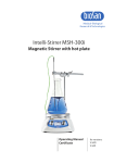
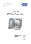
1
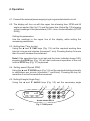
Medical–Biological
Research & Technologies
MR-12
Rocker-Shaker
Operating Manual
Certificate
for version
V.2AW
Contents
1. Safety Precautions
2. General Information
3. Getting Started
4. Operation
5. Specifications
6. Maintenance
7. Warranty and Claims
8. Declaration of Conformity
Page 2
1. Safety Precautions
The following symbol means:
Caution! Make sure you have fully read and understood the present
Manual before using the equipment. Please pay special
attention to sections marked by this symbol.
GENERAL SAFETY
·
Use only as specified in the operating manual provided.
The unit should be saved from shocks and falling.
·
The unit must be stored and transported only in a horizontal position
·
(see marking on the package).
After transportation or storage keep the unit under room temperature for
·
2–3 hrs before connecting it to the electric circuit.
Use only cleaning and decontamination methods recommended by the
·
manufacturer.
Do not make modifications in design of the unit.
·
ELECTRICAL SAFETY
·
Connect only to a electric circuit with voltage corresponding to that on
the serial number label.
·
Do not plug the unit into an ungrounded power socket, and do not use
an ungrounded extension lead.
·
Use only the external power supply unit provided with this product.
·
Ensure that the external power supply connector is easily accessible
during use.
·
Disconnect the unit from electric circuit before moving. Disconnect the
external power supply unit from power socket to turn off the unit.
·
If liquid penetrates into the unit, disconnect it from the external power
supply unit and have it checked by a repair and maintenance technician.
Page 3
DURING OPERATION
Do not impede the platform motion.
·
·
No objects or body parts can be placed between the plaform and shaker
body at any time.
Do not operate the unit in environments with aggressive or explosive
·
chemical mixtures.
Do not operate the unit if it is faulty or has been installed incorrectly.
·
Do not use outside laboratory rooms.
·
Do not place a load exceeding the maximum load value mentioned in
·
the Specifications section of this Manual.
BIOLOGICAL SAFETY
·
It is the user's responsibility to carry out appropriate decontamination if
hazardous material is spilt on or penetrates into the equipment.
2. General Information
MR-12 Rocker-Shaker provides adjustable soft (intensive) growth
media or solutions mixing in vessels or single use plastic bags placed on the
platform.
Adjusting speed and angle of the platform shaking user can optimize a
mixing process according to a task settled.
The device can be used for washing gels after electrophoresis, it is ideal
for biomolecule hybridization on strips and for staining and washing of strips
and slides.
When installed into a bioincubator, the shaker is ideal for incubating cells
and cell cultures in single use plastic bags with working volumes of up to 5
liters.
Rocker-Shaker is equipped with a system of platform overload automatic
detection. In the case of overload an error message is shown on the unit’s
display, accompanied by the sound signal. This option ensures long-term safe
operation.
Page 4
3. Getting started
3.1. Unpacking.
Remove packing materials carefully and retain them for future shipment
or storage of the unit.
Examine the unit carefully for any damage incurred during transit. The
warranty does not cover in-transit damage.
3.2. Complete set. Package contents:
MR-12 Rocker-Shaker ....................................................1 piece
detachable platform ........................................................1 piece
rubber mat........................................................................1 piece
four screws and a wrench .....................................................1 set
external power supply unit ................................................1 piece
power cord .......................................................................1 piece
Operating Manual; Certificate ...........................................1 copy
3.3. Set up:
place the unit upon firm stable even horizontal surface;
remove protective film from the display;
connect the power cord to the external power supply unit;
plug the external power supply unit into the 12 V socket at the rear side
of the unit.
3.4. Platform installation
install the platform on the unit and remove the rubber pad.
secure the platform on the supporting platform on top of the unit with
the four supplied screws.
cover the platform with the rubber mat.
-
Page 5
4. Operation
4.1. Connect the external power supply plug to a grounded electric circuit.
4.2. The display will turn on with the upper line showing time, RPM and tilt
angle set earlier (Set, fig.1/1) and the lower line (Actual fig.1/2) showing
current readings of the parameters (0:00 – time, mode indication (STOP/
RUN)).
Setting the parameters
Use the readings in the upper line of the display, while setting the
necessary parameters.
4.3. Setting time (Time hr:min)
TIME keys (Fig. 1/3) set the required working time
Using the p
and q
interval in hours and minutes (increment 1 min). Pressing the key for more
than 3 sec will increase the increment.
Note! If the operation time is not set and the timer indicator shows 0:00,
pressing the RUN key (Fig. 1/6) will start continuous operation of the unit
until the STOP key (Fig. 1/7) is pressed.
4.4. Setting speed (Speed RPM)
SPEED keys (Fig. 1/4) set the required shaking intensity
Using the p
and q
in oscillations per minute (increment 1 oscill/min). Pressing the key for
more than 3 sec will increase the increment.
4.5. Setting tilt angle (Angle Deg.)
ANGLE keys (Fig. 1/5) set the necessary angle
Using the p
and q
1
2
3
4
5
6
7
30:00
0:00
90
Time
(hr:min)
Speed
(RPM)
10
STOP
Run/Stop
RUN
Angle
(Deg.)
STOP
SPEED
Rocker-Shaker MR-12
Fig.1. Front panel
Page 6
ANGLE
(increment 1º). Pressing the key for more than 3 sec will increase the
increment.
The set parameters can also be changed during operation.
Program execution
4.6. Place samples on the platform, arranging the load symmetrically relative
to the tilt axis.
Caution! Do not place any objects between the platform and the shaker
body.
4.7. Press the RUN key (Fig. 1/6). The platform will start shaking and the timer
indicator will start counting up the time interval (with 1 min precision).
4.8. If the platform is overloaded, the device will make three attempts to
restart the operation (indication: DRIVER ERROR). If the attempts fail, a
flashing OVERLOAD reading will be shown on the display, accompanied
by the repetitive sound signal, until the STOP key (Fig. 1/7) is pressed.
Eliminate the causes of overload before restarting operation (see p. 4.6).
4.9. After the set time elapses, the platform motion will stop and the flashing
STOP reading will be shown on the display, accompanied by the
repetitive sound signal, until the STOP key is pressed.
4.10. If necessary the unit can be stopped at any time during operation before
the set time has elapsed by pressing the STOP key. In this case the
platform motion will stop when the platform achieves horizontal
position. Pressing the RUN key again will start the program from the
beginning (timer will be restarted).
4.11. After finishing the operation disconnect the external power supply unit
from electric circuit.
Page 7
5. Specifications
The unit is designed for operation in cold rooms, incubators and closed
laboratory rooms at ambient temperature from +4°C to +40°C and maximum
relative humidity 80% for temperatures up to 31°C decreasing linearly to 50%
relative humidity at 40°C.
5.1. Mixing frequency control range ...................................1 – 99 oscill/min
5.2. Mixing frequency setting resolution .....................................1 oscill/min
5.3. Tilt angle range
for 1 – 50 oscill/min range .......................................................0 – 10°
for 51 – 99 oscill/min range ...........................................................10°
5.4. Digital time setting ..............................1 min – 99 hrs 59 min / non-stop
5.5. Time setting resolution ..................................................................1 min
5.6. Maximum continuous operation time ........................................168 hrs
5.7. Maximum load .................................................................................5 kg
5.8. Platform working area ......................................................480x380 mm
5.9. Dimensions ...............................................................430x480x210 mm
5.10. Input current/power consumption ............................12 V, 1.1 A / 13 W
5.11. External power supply input AC 100-240 V 50/60 Hz, output DC 12 V
5.12. Weight* .....................................................................................11.9 kg
* Accurate within ±10%.
Replacement parts
Description
Catalogue number
PP-480
Detachable platform with non-slip
rubber mat
BS-010130-AK
Biosan is committed to a continuous programme of improvement and
reserves the right to alter design and specifications of the equipment without
additional notice.
Page 8
6. Maintenance
6.1. If the unit requires maintenance, disconnect the unit from electric circuit
and contact Biosan or your local Biosan representative.
6.2. All maintenance and repair operations must be performed only by
qualified and specially trained personnel.
6.3. Standard ethanol (75%) or other cleaning agents recommended for
cleaning of laboratory equipment can be used for cleaning and
decontamination of the unit.
Page 9
7. Warranty and Claims
7.1. The Manufacturer guarantees the compliance of the unit with the
requirements of Specifications, provided the Customer follows the
operation, storage and transportation instructions.
7.2. The warranted service life of the unit from the date of its delivery to the
Customer is 24 months. Contact to your local distributor to check
availability of extended warranty.
7.3. If any manufacturing defects are discovered by the Customer, an
unsatisfactory equipment claim shall be compiled, certified and sent to
the local distributor address. Please visit www.biosan.lv, Technical
support section to obtain the claim form.
7.4. The following information will be required in the event that warranty or
post-warranty service comes necessary. Complete the table below and
retain for your records.
Model
Serial number
Date of sale
Page 10
MR-12 Shaker-Rocker
8. Declaration of Conformity
Version 2.01 – October 2013