1
Medical–Biological
Research & Technologies
MM-1000
Overhead stirrer
Multi Mixer
Operating Manual
Certificate
for version
V.2AW
Contents
1. Safety Precautions
2. General Information
3. Getting Started
4. Operation
5. Program setting
6. Specifications
7. Maintenance
8. Warranty and Claims
9. Declaration of Conformity
Page 2
1. Safety Precautions
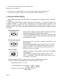
The following symbol means:
Caution! Make sure you have fully read and understood the present Manual
before using the equipment. Please pay special attention to sections
marked by this symbol.
GENERAL SAFETY
·
Use only as specified in the Operating Manual provided.
·
The unit should be saved from shocks or falling.
·
After transportation or storage keep the unit under room temperature for 2-3hrs
before connecting to electric circuit.
·
Use only cleaning and decontamination methods recommended by the
manufacturer.
·
Do not make modifications to the design of the unit.
ELECTRICAL SAFETY
·
Connect only to an external power supply unit with voltage corresponding to that
on the serial number label.
·
Use only the external power supply unit provided with this product.
·
Ensure that the switch and external power supply unit are easily accessible
during use.
·
Disconnect the external power supply unit from electric circuit before moving the
unit.
·
If liquid penetrates into the unit, disconnect it from the external power supply unit
and have it checked by a repair and maintenance technician.
DURING OPERATION
Avoid contact of any parts of clothing or body with the moving parts of the unit.
·
Avoid contact the stirrer with the flask surfaces.
Stop operation if strong vibration of the unit occurs. In this case it is necessary to
·
reduce the speed or remedy the reason of imbalance.
·
Do not operate the unit in environments with aggressive or explosive chemical
mixtures.
·
Do not operate the unit if it is faulty or has been installed incorrectly.
·
Do not use outside laboratory rooms.
Page 3
Do not leave the operating unit unattended.
·
BIOLOGICAL SAFETY
·
It is the user's responsibility to carry out appropriate decontamination if
hazardous material is spilt on or penetrates into the equipment.
2. General Information
MM-1000 Overhead stirrer Multi Mixer is designed for mixing solutions of different
viscosity.
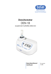
Multi Mixer MM-1000 provides three types of motion: 1) rotational motion, 2)
reciprocal motion, 3) vibro motion, according to the microprocessor protocol. The
protocol enables making not only programs that include mixing motion of one
particular type, but also programs that alternate mixing motions of different types
cyclically.
Rotational motion
Simple even rotation with an option of shifting direction
(clockwise/counterclockwise) after set time.
The speed adjustment range is from 40 to 1000 rpm with
10 rpm increment. The motion time can be set in 0 to 250
sec range or non-stop.
Reciprocal motion
Reciprocal motion direction changing, limited by the
turning angle.
The turning angle adjustment range is from 0° to 360°
with 30° increment. The speed is the same as set for
rotational motion. The motion time can be set in 0 to
250 sec range or non-stop.
Vibro motion
Intensive mixing at high speed with small adjustable
turning angle.
The turning angle adjustment range is from 0° to 5°
with 1° increment. The motion time can be set in 0 to 5
sec range or non-stop.
Reciprocating and Vibro motion types can be replaced by a pause.
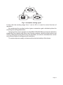
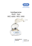
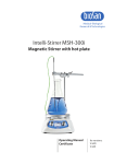
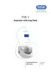
These 3 motions are combined in a cycle and can be used:
- separately (only 1; 2; or 3);
- in combinations by two (1
- all three in one cycle (1
Page 4
2;2
2
3 ;3
3) (Fig. 1).
1 );
1
3
2
Fig.1. Innovative mixing cycle
A timer with the working range from 1 min to 96 hr is used to control the time of
operation.
By combining the provided motion types a researcher gets unlimited options for
choosing the mixing parameters.
Apart from the unique operation modes MM-1000 Multi Mixer possesses attractive
elegant BioForm design and offers user-friendly interface, which provides options not
only for changing the program during the operation, but also for simultaneous control
over different steps of mixing protocol realisation.
The external power supply unit ensures the electrical safety of the device.
Page 5
3. Getting started
3.1 Unpacking.
Remove packing materials carefully and retain them for future shipment or
storage of the unit.
Examine the unit carefully for any damage incurred during transit. The warranty
does not cover in-transit damage.
Do not apply excessive force on the clamping chuck.
At moving hold the unit at the housing, not at the
clamping chuck.
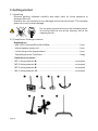
3.2 Complete set. Package contents:
Standard set
MM-1000 Overhead Stirrer Multi Mixer .................................................1 pce.
external power supply unit .....................................................................1 pce.
rod for fixing on the support stand...........................................................1 pce.
Operating manual, Certificate ..............................................................1 copy
Optional accessories
-
MP-1 stirring element u
..................................................................on request
-
МР-2 stirring element v
..................................................................on request
-
МР-3 stirring element w
..................................................................on request
-
МA-1 stirring element x
.................................................................on request
Page 6
-
МС-1 stirring element y
..................................................................on request
-
double clamp z
...............................................................................on request
support stand {
..............................................................................on request
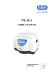
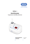
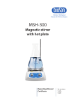
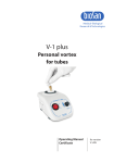
3.3 Set up (fig.2):
- screw the nut (fig.2/2) on the support stand (fig.2/1);
- screw in the support stand (fig.2/1) in the opening (fig.2/4) on the rear side of
the Multi Mixer. Tighten the nut (fig.2/2) turning it clockwise to fasten the fixing
rod;
- fasten the unit on the stand using the double clamp;
- fasten the stirring element axle (fig.2/6) in the
clamping chuck (fig.2/5) without applying
excessive force sideways;
- connect the external power supply unit to the
socket (fig.2/3);
- remove protective film from the display.
1 2 3
4
5
6
Fig.2 Set up
Page 7
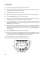
4. Operation
4.1. Connect the external power supply unit to electric circuit.
4.2. Dip the stirrer inside the vessel with the liquid being mixed. The stirring element
should be completely dipped into the liquid.
4.3. Turn ON the power switch on the front panel.
4.4. Set the required program and operation time (see Section 5. Program Setting).
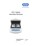
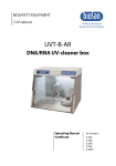
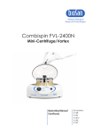
4.5. Press the Run/Stop key (fig.3/5) to start the program.
4.6. The stirrer motion will begin and the corresponding indication (RUN, fig.3/3 and
the changing time values, fig.3/2) will be shown on the display.
4.7. If the operation time is not set and the Time indicator (fig.3/2) shows 0:00,
pressing the Run\Stop key will start continuous operation of the unit until the
Run\Stop key is pressed again.
4.8. If the operation time is set then the unit will stop after the set time interval elapses
(flashing indication STOP (fig.3/3) will be shown on the display) and give a
repetitive sound signal about the end of operation (press the Run\Stop key to
stop the signal).
4.9. Press the Run/Stop key to repeat the preset program.
4.10. The unit can be stopped at any time during operation before the set time elapses
if necessary by pressing the Run\Stop key. Pressing the Run\Stop key again
will start the program from the beginning (timer will be restarted).
4.11. After finishing the operation turn OFF the power switch.
4.12. Unplug the external power supply unit from electric circuit.
2
CW
(rpm)
1
CW/CCW
(deg.)
200 180
OFF 60
Vibro/
/pause
5
5
Time
(hr:min)
0:00
RUN
Time (sec.)
Select
Run
Stop
Fig. 3 Control panel
Page 8
3
4
5
5. Program setting
The program consists of cycles. Each cycle includes three different types motions
(Rotational, Reciprocating and Vibro) set one after another with the duration from 0 to
250 seconds for Rotational and Reciprocal motion types and from 0 to 5 seconds for
Vibro motion.
5.1. Press the Select key (Fig.3/1) to choose the parameter to change (each pressing
of the Select key consecutively activates the parameters in the cycle; the active
parameter is flashing).
Use the ▲ and ▼ keys (Fig.3/4) to set the necessary value. Pressing the key for
more than 2 sec will increase the increment.
5.2. The program can also be changed during the operation - microprocessor
automatically enters the last changes into the memory as the working program
(excluding overall operation time).
5.3. Set the following parameters: speed, turning angle, time for each motion type and
overall operation time.
5.4. If the time for a motion is set to zero (indication OFF), this type of motion will be
skipped in the cycle.
5.5. A pause can be set instead of
Reciprocal (0-250 sec) or Vibro
(0-5 sec) motion. Set the
turning angle of Reciprocal or
Vibro motion to zero to set the
pause. The time, set for this
motion type, will be the pause
duration. The stirrer will not
move in this mode during the
operation, but the time will be
counted down.
5.6. The overall timer (fig.3/2) is used
to control the operation time. The
timer can be set for the period
from 1 min to 96 hours (timer
increment is 1 min).
5.7. Table 1 shows possible motion
combinations in the cycle.
1
2
3
4
5
6
7
8
9
10
11
12
13
14
Rotational
motion
On
On
On
On
On
On
On
On
On
OFF
OFF
OFF
OFF
OFF
Reciprocal
motion
On
OFF
Pause
OFF
Pause
OFF
Pause
On
On
On
Pause
On
OFF
On
Vibro
motion
On
On
On
OFF
OFF
Pause
Pause
OFF
Pause
On
On
Pause
On
OFF
Table 1. Motion combinations
Page 9
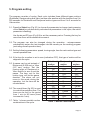
5.8. Further examples illustrate program setting for both separate motions and their
combinations in the cycle.
5.8.1. Rotational motion
Set the speed (A) (40 - 1000 rpm) and time (B) (1 - 250 sec) of Rotational motion.
Turn off Reciprocal motion by setting time (C) of Reciprocal motion to zero (OFF).
Turn off Vibro motion by setting time (D) of Vibro motion to zero (OFF).
Note that Multi Mixer is programmed to change the rotation direction each time
when the motion timer is started, i.e. if the rotational motion time is set to 30 sec
then the direction of rotation will be changed every 30 sec.
A
RPM
200
30
180
5 0:00
OFF OFF STOP
0
Time, s
Time (sec.)
B
Cycle 1
C
Cycle 2
Cycle 3
…
D
Orbital motion run in cycles
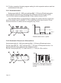
5.8.2. Rotational + Reciprocal + Vibro motions
Set the speed (A) (40 - 1000 rpm) and time (D) (1 - 250 sec) of Rotational motion.
Set the angle (B) (30 - 360º) and time (E) (1 - 250 sec) of Reciprocal motion. It is
performed at the same speed as the rotational motion.
Set the turning angle (C) (1-5º) and time (F) (1 - 5 sec) for Vibro motion.
A
B
C
200
240
180
60
RPM
5
5
0:00
STOP
0
Time, s
Time (sec.)
D
Page 10
E
F
Cycle 1
Cycle 2
…
Rotational, Reciprocal and Vibro
motions run one after another in
cycles
5.8.3. Rotational + Reciprocal motions + Pause
Set the speed (A) (40 - 1000 rpm) and time (D) (1 - 250 sec) of Rotational motion.
Set the turning angle (B) (30 - 360º) and time (E) (1 - 250 sec) of Reciprocal motion. (It
is performed at the same speed as the rotational motion.)
Set the turning angle (C) of Vibro motion to zero. Set the time (F) of Vibro motion (1 - 5
sec) - this is the time of pause duration.
A
B
C
200
240
180
60
RPM
0
5
0:00
STOP
0
Time (sec.)
D
Time, s
F
E
Cycle 1
Cycle 2
…
Rotational motion, Reciprocal motion
and pause run one after another in
cycles.
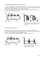
5.8.4. Vibro motion + Pause
Turn off Rotational motion by setting time (C) of Rotational motion to zero (OFF).
Set the turning angle (A) of Reciprocal motion to zero. Set the time (D) for Reciprocal
motion (1 - 250 sec) - this is the time of pause duration.
Set the turning angle (B) (1-5º) and time (E) (1 - 5 sec) for Vibro motion.
A
B
RPM
200
OFF
00
10
5
5
0:00
STOP
0
Time, s
Time (sec.)
C
D
E
Cycle 1
Cycle 2
…
Vibro motion and pause run one
after another in cycles.
Page 11
6. Specification
The unit is designed for operation in cold rooms, incubators and closed laboratory
rooms at ambient temperature from +4°C to +40°C and maximum relative humidity
80% for temperatures up to 31°C decreasing linearly to 50% relative humidity at 40°C.
6.1. Rotational motion
Speed range ................................................40 - 1000 rpm (increment 10 rpm)
Timer .................................................................................................0 - 250 sec
6.2. Reciprocal motion
Turning angle .............................................................0º - 360° (increment 30º)
Timer ................................................................................................0 - 250 sec
6.3. Vibrating motion
Turning angle ...................................................................0º - 5° (increment 1º)
Timer ....................................................................................................0 - 5 sec
6.4. General timer of operation ............1 min - 96 hrs (increment 1 min) /non-stop
6.5. Maximal stirring volume (water) .................................................................20 l
6.6. Maximal stirring liquid viscosity ......................................................1000 mPa.s
6.7. Dimensions (w/out rod) ....................................................140 x 135 x 250 mm
6.8. Rod for fixing on the support stand, diam. x lenght ...........Ø 12 mm x 260 mm
6.9. Stirrer shaft ..........................................................................................Ø 8 mm
6.10. Input current/power consumption ..................................12 V, 700 mA / 8,4 W
6.11. External power supply............ input AC 100-240 V 50/60 Hz, output DC 12 V
6.12. Weight*...................................................................................................2.4 kg
* Accurate within ±10%.
Optional
accessories
Description
Catalogue number
MP-1
Paddle stirring element,
378x(70x70)x8 mm
BS-010306-AK
MP-2
Propeller stirring element, 2 folding blades
326x55x8 mm
BS-010306-BK
MP-3
Propeller stirring element 3 folding blades
325x50x8 mm
BS-010306-CK
MA-1
Anchor stirring element, 332x90x8 mm
BS-010306-DK
MC-1
Centrifugal stir.elem., 358x60(110)x8 mm
BS-010306-EK
Double clamp
for unit fixing
VELA00001300
Support stand
for unit fixing, 40x30x87 cm
VEL A00001301
Biosan is committed to a continuous programe of improvementand reserves the
right to alter design and specifications of the equipment without additional notice.
Page 12
7. Maintenance
7.1. If the unit requires maintenance, disconnect the unit from electric circuit and
contact Biosan or your local Biosan representative.
7.2. All maintenance and repair operations must be performed only by qualified and
specially trained personnel.
7.3. Standard ethanol 75% or other cleaning agents recommended for cleaning of
laboratory equipment can be used for cleaning and decontamination of the unit.
Page 13
8. Warranty and Claims
8.1. The Manufacturer guarantees the compliance of unit with the requirements of
Specifications, provided the Customer follows the operation, storage and
transportation instructions.
8.2. The warranted service life of unit from date of delivery to the Customer is 24
months. Contact your local distributor to check availability of extended warranty.
8.3. If any manufacturing defects are discovered by the Customer, an unsatisfactory
equipment claim shall be compiled, certified and sent to the local distributor
address. Please visit www.biosan.lv, Technical support section to obtain the
claim form.
8.4. The following information will be required in the event that warranty or postwarranty service comes necessary. Complete the table below and retain for your
records.
Model
Serial number
Date of sale
Page 14
MM-1000 Overhead Stirrer Multi Mixer
9. Declaration of Conformity
Page 15
Biosan SIA
Ratsupites 7, build. 2, Riga, LV-1067, Latvia
Phone: +371 6742 6137
Fax: +371 6742 8101
http://www.biosan.lv
Version 2.01 - January 2013