1
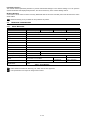
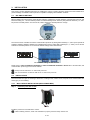
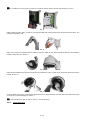
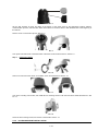
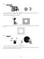
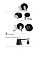
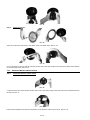
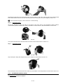
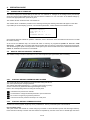
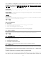
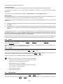
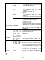
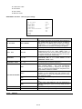
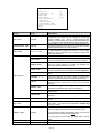
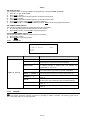
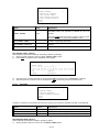
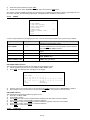
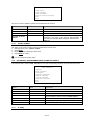
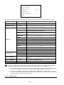
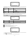
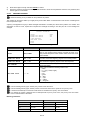
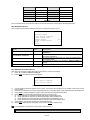
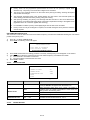
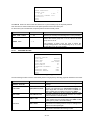
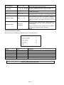
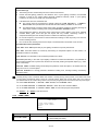
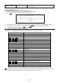
Pic. 26 Pull cables into the back box into the plastic panel. Connect cables to hole of pin. Insert the hole of pin inside the back board. When finished, close the door to the back board and turn on the power. The LED will light up. See Pic. 26. If the LED does not light up, refer to Section 5: Trouble Shooting. Step 2. Install dome drive Set the DIP switches for SW1 and SW2 on the bottom of the dome drive for the appropriate receiver address, communication protocol, and baud rate. Refer to the labels on the dome drive or DIP SWITCH SET in this manual. Pic. 27 Line up link card and faucet of the back board of the dome. Push the dome drive in. See Pic. 27. Step 3. Install dome flange Pic. 28 Snip a flake piece. Keep three flanges away from two clamps on the back board. See Pic. 28. Pic. 29 Push the flange of dome into the back board. Take out the membrane on the clarity flake of the dome drive. See Pic. 29. 3.2.4. POLE MOUNT INSTALLATION See Section 3.2.1 Wall Mount Installation. 11 / 43