Download User Manual - INTEC Controls
Transcript
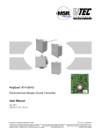
PolyGard AT-1195 v1 Electrochemical Oxygen Transmitter Serial No. EC-S – 003_O2 User Manual January 20, 2009 PolyGard£ is a registered trademark of MSR Phone: (858) 578-7887 & (888) GO INTEC Fax (858) 578-4633 & (888) FX INTEC Specification subject to change without notice. INTEC Wilson Mohr, Inc., 9730 Distribution Ave., San Diego, CA 92121 www.inteccontrols.com Printed in USA 090120 User Manual PolyGard® O2 AT-1195 v1 Page 2 1 Intended Use............................................................................................................3 2 Functional Description ..........................................................................................3 3 Mounting ..................................................................................................................4 3.1 3.2 4 Electrical Connection ............................................................................................4 4.1 4.2 4.3 5 Zero-point calibration.................................................................................................................. 6 Gain calibration........................................................................................................................... 6 Calculation of control voltage ..................................................................................................... 6 Commissioning of the Option Relay Package AT-2R................................................................. 6 Selection of open-circuit/closed-circuit current operation ....................................................... 6 Adjust switching threshold voltage.......................................................................................... 7 Calculation of switching threshold voltage .............................................................................. 7 Select switching hysteresis ..................................................................................................... 7 Maintenance and Inspection ................................................................................8 6.1 6.2 6.3 7 Instruction ................................................................................................................................... 4 Wiring connection ....................................................................................................................... 5 Mounting option relay package AT-2R ....................................................................................... 5 Commissioning .......................................................................................................5 5.1 5.2 5.3 5.4 5.4.1 5.4.2 5.4.3 5.4.4 6 Mounting instructions.................................................................................................................. 4 Installation .................................................................................................................................. 4 Inspections ................................................................................................................................. 8 Calibration .................................................................................................................................. 8 Exchange of sensor element ...................................................................................................... 8 Troubleshooting .....................................................................................................8 7.1 7.2 Diagnostics at the transmitter ..................................................................................................... 8 Diagnostics at option relay package AT-2R ............................................................................... 9 8 Technical Data ......................................................................................................10 9 Figures ....................................................................................................................11 10 Notes and General Information .........................................................................13 10.1 10.2 10.3 10.4 Intended product application .................................................................................................... 13 Installer’s responsibilities.......................................................................................................... 13 Maintenance ............................................................................................................................. 13 Limited warranty ....................................................................................................................... 13 PolyGard£ is a registered trademark of MSR Phone: (858) 578-7887 & (888) GO INTEC Fax (858) 578-4633 & (888) FX INTEC Specification subject to change without notice. INTEC Wilson Mohr, Inc., 9730 Distribution Ave., San Diego, CA 92121 www.inteccontrols.com Printed in USA 090120 User Manual PolyGard® O2 AT-1195 v1 Page 3 Electrochemical Oxygen Transmitter 1 Intended Use The PolyGard O2 Analog Transmitter AT-92-1195 with 4 – 20 mA output and 2-wire connection is used for the continuous monitoring of the oxygen concentration (O2) in the ambient air. Main fields of application are in laboratories, food production etc. where changes of the oxygen content are possible. The sites intended for use are all areas being directly connected to the public low voltage supply, e.g. domestic, commercial and industrial ranges as well as small enterprises. The PolyGard O2 Analog Transmitter is not suitable for the application in areas exposed to explosive hazards. 2 Functional Description The chemical process of the measurement is based upon the principle of a galvanic micro-fuel cell. The target gas and/or the ambient air diffuse through a filtering membrane into the measuring cell to the cathode. Cathode and anode of the sensor are electrically in contact, therefore due to the oxidation there is an electric current proportional to the oxygen partial pressure. This current is translated into a 4 to 20 mA signal by the succeeding amplifier. The diffusion through the membrane and the thin electrolytic coating are complex, temperature-dependant, electrochemical processes which have an influence on the ion current of the sensor. Therefore the sensor is temperature compensated within a specified temperature range. The electrolyte, the material of the cathode and the composition of the anode are designed in a way that the oxygen diffusing to the cathode is reduced electro-chemically. The electrolyte is used up by the electro-chemical process. Thus the life expectance of the sensor is limited to two years. Calibration during the sensor life is not necessary. Option relay package AT-2R: With the PolyGard AT-2R relay package two potential-free contacts are available for the connection to external devices. The switching thresholds of these relays are selectable via potentiometer in the range of 10 - 90 % of the O2 concentration. The hysteresis is programmable via jumpers. Additionally the relay mode, open-circuit or closed circuit, is selectable. The status of the two relays is displayed via LED. Note: There is a small quantity of corrosive liquid in the sensor elements. If in case of damage persons or objects touch the liquid, you have to clean the affected areas as fast and carefully as possible with tap water. Out of use sensors must be disposed in the same way as batteries. PolyGard£ is a registered trademark of MSR Phone: (858) 578-7887 & (888) GO INTEC Fax (858) 578-4633 & (888) FX INTEC Specification subject to change without notice. INTEC Wilson Mohr, Inc., 9730 Distribution Ave., San Diego, CA 92121 www.inteccontrols.com Printed in USA 090120 User Manual PolyGard® O2 AT-1195 v1 Page 4 3 Mounting Caution: Electronics can be destroyed by static electricity. Therefore, do not touch the equipment without a wrist strap connected to ground or without standing on conductive floor. 3.1 Mounting instructions When choosing the mounting site please pay attention to the following: • Installation 1.5 m to max. 1.8 m above floor-level. • Select the location of the sensor according to local regulations. • Consider the ventilation conditions! Do not mount the transmitter in the center of the airflow (air passages, suction holes) • Mount the transmitter at a location with minimum vibration and minimum variation in temperature (avoid direct sunlight). • Avoid locations where water, oil etc. may influence proper operation and where mechanical damage might be possible. • Provide for adequate space for maintenance and calibration work. Air duct mounting • Mount only in a duct section with minimum air vortex. Keep a minimum distance of 1 m (3,5 feet) from any curve or obstacle. • Mount only in a duct system with a maximum air velocity of 10 m/s (2000 ft/min) or less. • Mounting must be performed so that the airflow is in line with probe openings. 3.2 Installation • Open cover of enclosure. • Unplug basic PCB from terminal blocks. • Fix bottom part by screws vertically to the wall (terminal blocks to the ground). • Plug in the basic PCB at X4 and X5. • Replace the cover. 4 Electrical Connection 4.1 Instruction Consider static electricity! See 3. Mounting. • Installation of the electrical wiring should only be performed by a trained specialist according to the connection diagram, without any power applied to conductors and according to the corresponding regulations! • Avoid any influence of external interference by using a shielded cable. • Recommended cable: Belden Twisted Shielded. maximum resistance 73 Ω/km • Cable for Relay Package AT-2R: no recommendations. • When the PBC is mounted, it is important to ensure that the wire shields or any bare wires do not short the PCB. PolyGard£ is a registered trademark of MSR Phone: (858) 578-7887 & (888) GO INTEC Fax (858) 578-4633 & (888) FX INTEC Specification subject to change without notice. INTEC Wilson Mohr, Inc., 9730 Distribution Ave., San Diego, CA 92121 www.inteccontrols.com Printed in USA 090120 User Manual PolyGard® O2 AT-1195 v1 Page 5 4.2 Wiring connection • Open cover of enclosure. • Unplug basic PCB from terminal blocks X4 and X5. • Enter cable through hole; connect cable leads to the terminal block. • Re-plug basic PCB in the terminal blocks X4, X5. • Close cover. 4.3 Mounting option relay package AT-2R Consider static electricity! See 3. Mounting. • Unplug PCB EC- S from terminal blocks fixed on base. • Plug in the relay package at the multipoint connector X2 to the PCB EC- S. See Fig. 2. • Secure by the enclosed screw M2,5x 6 at the back side of the PCB EC- S. • Re-plug basic PCB in the terminal blocks X4, X5. 5 Commissioning Caution: Prior to calibration the sensor element must be fully stabilized by applying power voltage for at least one hour without interruption. Follow commissioning instructions at any exchange of sensor elements. Only trained technicians should perform the following: • Check mounting location. • Check power voltage. • Check PCB EC-S for correct mounting at X4 and X5. • Check sensor element (O2 - A2) for correct mounting at terminal X3 of the PCB EC-S. • Calibration of the transmitter (if not already factory-calibrated) Required instruments for commissioning of the transmitter: • Test gas bottle with target gas O2, in the range of 20 - 25 % vol. (alternatively ambient air with 20,9 % vol.) • Gas pressure regulator with flow meter • Sensor calibration adapter with tube. Type: CONKIT-COMB-AT. See Fig. 4 • Digital voltmeter with range 0 - 10V DC, accuracy 1%. • Screwdriver small. Caution: Please observe proper handling procedures for test gas bottles! PolyGard£ is a registered trademark of MSR Phone: (858) 578-7887 & (888) GO INTEC Fax (858) 578-4633 & (888) FX INTEC Specification subject to change without notice. INTEC Wilson Mohr, Inc., 9730 Distribution Ave., San Diego, CA 92121 www.inteccontrols.com Printed in USA 090120 User Manual PolyGard® O2 AT-1195 v1 Page 6 5.1 Zero-point calibration For the zero-point calibration the 4 mA signal is adjusted without the sensor. The zero-point is already factorycalibrated and only in case of exchange of the sensor the zero-point calibration must be carried out again. • Remove the sensor from X3. • Connect digital voltmeter to test pin X6 "Test" for zero-point calibration. • Adjust the value 200 mV with the potentiometer "Zero". • Ready. • Plug the sensor in X6 again. 5.2 Gain calibration • Connect calibration adapter to the sensor element. • Connect digital voltmeter to the test pin X6. • Apply span calibration gas 20 – 25 % vol. O2, (300ml/min,; 1 Bar) • Wait 2 minutes until the sensor is stable, adjust control voltage with potentiometer ”Gain” until the signal corresponds to the calculated value, see formula section 5.3 ± 3 mV. • Remote calibration adapter with a careful light turn. Inspect the correct mounting of the sensor element Alternatively apply ambient air, 20,9 % vol. (only if concentration is known). 5.3 Calculation of control voltage Control voltage (mV) = 800 (mV) x Test gas concentration O2 (% vol.) + 200 (mV). Measuring range O2 (% vol.) Example: Measuring range O2 25 % vol. O2 Test gas concentration 20.9 % vol. O2 Control voltage 869 mV 800 (mV) x 20,9 (% vol.) + 200 (mV) = 869 mV. 20.9 (% vol.) 5.4 Commissioning of the Option Relay Package AT-2R Note: Option relay package only possible in 3-wire technique. 5.4.1 Selection of open-circuit/closed-circuit current operation Each relay can be configured to open-circuit current operation or closed-circuit current operation via jumper. Take the position of the jumpers from the following table. Closed-circuit mode Relay R9 Jumper in position 9 and 11 Relay R10 Jumper in position 20 and 18 Open-circuit mode 10 and 12 19 and 21 Factory-set: Closed-circuit mode PolyGard£ is a registered trademark of MSR Phone: (858) 578-7887 & (888) GO INTEC Fax (858) 578-4633 & (888) FX INTEC Specification subject to change without notice. INTEC Wilson Mohr, Inc., 9730 Distribution Ave., San Diego, CA 92121 www.inteccontrols.com Printed in USA 090120 User Manual PolyGard® O2 AT-1195 v1 Page 7 5.4.2 Adjust switching threshold voltage Required instruments: • Digital multimeter with range 0 – 10 VDC, accuracy 1%. • Screwdriver small. Switching threshold voltage can be adjusted in the range of 1 V – 9 V, 10 % - 90 % of the measuring range. Adjust switching voltage for relay R 9 • Connect digital multimeter to X9 + and -. Observe polarity! • Adjust calculated switching voltage ± 10 mV, see section 5.4.3. by potentiometer P9. Adjust switching voltage for relay R 10 • Connect digital multimeter to X10 + and X9 -. Observe polarity! • Adjust calculated switching voltage ± 10 mV, see section 5.4.3. by potentiometer P10. 5.4.3 Calculation of switching threshold voltage U threshold (mV) = 8000 (mV) x alarm threshold O2 (% vol.) + 2000 (mV). Measuring range O2 (% vol.) Example: Measuring range O2 25 % vol. Alarm threshold O2 18 % vol. U threshold 7760 mV 8000 (mV) x 18 (% vol.) + 2000 (mV) = 7760 mV. 25 % vol. 5.4.4 Select switching hysteresis The switch-off threshold is calculated according to the following formula: Uoff = Uthreshold – Uhysteresis The switching hysteresis can be selected via jumper to 5% or 10% of the measuring range. Depending on the calculated switching voltage one jumper for each relay has to be plugged into the correct position in order to select either 5% or 10%. See table below for jumper positions. Calculated threshold voltage (V) 1.00 – 3.50 3.51 – 6.50 6.51 – 9.00 Switching hysteresis (%) 5 Relay 9 Jumper in position Relay R10 Jumper in position 7 16 10 5 14 5 4 13 10 6 15 5 5 14 10 8 17 Caution If the calculated voltage is below 1.50 V, it’s not allowed to adjust a switching differential of 10%. The triggered alarm relay would not reset. PolyGard£ is a registered trademark of MSR Phone: (858) 578-7887 & (888) GO INTEC Fax (858) 578-4633 & (888) FX INTEC Specification subject to change without notice. INTEC Wilson Mohr, Inc., 9730 Distribution Ave., San Diego, CA 92121 www.inteccontrols.com Printed in USA 090120 User Manual PolyGard® O2 AT-1195 v1 Page 8 6 Maintenance and Inspection 6.1 Inspections For regular examination and calibration of the transmitters by trained technicians we recommend to conclude a service contract with INTEC Wilson Mohr. Maintenance and inspection has to be done in regular intervals. 6.2 Calibration (see section 5.1 and 5.2) • At commissioning and at periodic intervals determined by the person responsible for the gas detection system (recommendation: every 24 months) • After exchange of the sensor element • If in case of aging, operational or climatic influences the sensitivity of the sensor falls below 60 % in operation, calibration will not be possible any more. Then the sensor has to be changed. 6.3 Exchange of sensor element Consider static electricity! See section 3. Sensor should always be installed without voltage applied • Unplug basic PCB EC-S carefully from the terminal blocks. • Unplug old sensor element from the PCB EC - S. • Take new sensor element out of original packing. • Plug in sensor element into the PCB EC-S at X3. • Plug in carefully the PCB EC-C at terminal blocks X4 and X5. • Calibrate sensor element (see section 5.1 and 5.2). 7 Troubleshooting 7.1 Diagnostics at the transmitter Trouble Cause Solution Output signal 0 mA and/or control voltage 0V Power voltage not applied Measure power voltage at terminal block X4 terminal 3 (+) and 2(-) (18 – 28 VDC) Basic PCB EC-S not plugged in correctly at X4 and X5 Plug in the basic PCB EC-S correctly Sensor element not calibrated Calibrate sensor element Sensor sensivity < 40% Replace sensor element Output signal < 3 mA and/or control voltage < 150 mV Control current signal not correct If faults cannot be eliminated by the above mentioned actions or if other faults not described in this table occur, please contact the service. PolyGard£ is a registered trademark of MSR Phone: (858) 578-7887 & (888) GO INTEC Fax (858) 578-4633 & (888) FX INTEC Specification subject to change without notice. INTEC Wilson Mohr, Inc., 9730 Distribution Ave., San Diego, CA 92121 www.inteccontrols.com Printed in USA 090120 User Manual PolyGard® O2 AT-1195 v1 Page 9 7.2 Diagnostics at option relay package AT-2R Trouble Cause No relay switching Board AT-2R not installed correctly Incorrect relay switching No relay switching at calculated threshold setting Relay return differential too long Solution Plug in AT-2R correctly into board Jumper JP 9 – 12 and/or 18 - 21 not See fig. 3 for correct setting installed See fig. 3 for correct setting Jumper JP 9 – 12 and/or 18 – 21 not installed correctly (open and closed circuit mode) Switching voltage adjusted and/or calculated incorrectly Differential jumper not correct Check switching voltage Check jumper position PolyGard£ is a registered trademark of MSR Phone: (858) 578-7887 & (888) GO INTEC Fax (858) 578-4633 & (888) FX INTEC Specification subject to change without notice. INTEC Wilson Mohr, Inc., 9730 Distribution Ave., San Diego, CA 92121 www.inteccontrols.com Printed in USA 090120 User Manual PolyGard® O2 AT-1195 v1 Page 10 8 Technical Data Electrical Power supply Power consumption - with relay package 18 - 28 VDC, reverse polarity protected 22 mA, max. (0.6 VA) 35 mA, max. (1.0 VA) Sensor Performance Type of gas Sensor element Measuring range Accuracy Long term zero-point drift Response time Sensor life expectancy Mounting height Oxygen (O2) Electrochemical, diffusion 0 – 25 % vol 0.1 % vol < 4 % of measured value /year t90 ≤ 190 s from 20.9 % to 0 % O2 2 years/normal operating environment 1.5 to 1.8 m Output signal Analog output signal Proportional, 4 – 20 mA, load ≤ 500 Ω overload and short-circuit protected Optional 2 x relay contacts, potential-free, max 30 VAC/DC, 0,5 A Operating Environment Humidity Range Working temperature Storage temperature Pressure range 0 - 95 % RH non-condensing -10 °C to + 50 °C 5 °C to 30 °C Atmospheric ± 10 % Physical characteristics Enclosure material Enclosure color Dimensions Weight Protection class Mounting Cable entry Wire connection Wire distance Approvals/Listings Warranty Depending on type Depending on type Depending on type Depending on type Depending on type Wall mounting, pillar mounting, duct mounting, depending on type Standard 1 x M 20 Screw type terminal min. 0.25 mm2, max. 2.5 mm2 Max. loop resist. 500 Ω (= wire resistor + controller input resistor) EMV directive 89/336/EWG CE One year / material (without sensor) PolyGard£ is a registered trademark of MSR Phone: (858) 578-7887 & (888) GO INTEC Fax (858) 578-4633 & (888) FX INTEC Specification subject to change without notice. INTEC Wilson Mohr, Inc., 9730 Distribution Ave., San Diego, CA 92121 www.inteccontrols.com Printed in USA 090120 User Manual PolyGard® O2 AT-1195 v1 Page 11 9 Figures Application Fig.1 shield 4-20 mA 24 VDC 0 VDC 7 shield 6 shield 5 shield 4 4-20 mA 3 24 VDC 2 0 VDC 1 X4 Transmitter ATX2-11XX Zentralgerät Central Controller X5 1 * 2 3 R10 * 4 5 R9 *Ruhestromprinzip De-energized operation NO NC COM NO COM Option: Relay Package O VDC: Nur bei Option Relay Package Only, with Option Relay Package Option Relay Package AT 2R Fig. 3 12 11 10 9 K10 K9 X2 X2 X9 P9 - X10 1 21 20 19 18 9 8 P10 K9 7 6 AT-2R 001 170299 K10 4 3 2 1 P2 X2 1 P1 1 2 3 4 5 6 7 Sensor 9 X2 X9 P9 P10 X10 AT-2R 001 170299 + Zero 4 5 K9 + Gain K10 4 4-20mA 3 24 V 2 GND 1 NC 17 + 5 X6 + Test 16 15 Position Jumper No. + X4 7 6 13 14 Position Jumper No. K9 Position Jumper No. K10 Board PCB/S AT1195 Fig.2 X5 1 NO1 2 NC1 3 COM1 4 NO2 5 COM2 EC-S-002 240703 PolyGard£ is a registered trademark of MSR Phone: (858) 578-7887 & (888) GO INTEC Fax (858) 578-4633 & (888) FX INTEC Specification subject to change without notice. INTEC Wilson Mohr, Inc., 9730 Distribution Ave., San Diego, CA 92121 www.inteccontrols.com Printed in USA 090120 User Manual PolyGard® O2 AT-1195 v1 Page 12 Calibration set-CONKIT-COMB-AT Fig. 4 PolyGard£ is a registered trademark of MSR Phone: (858) 578-7887 & (888) GO INTEC Fax (858) 578-4633 & (888) FX INTEC Specification subject to change without notice. INTEC Wilson Mohr, Inc., 9730 Distribution Ave., San Diego, CA 92121 www.inteccontrols.com Printed in USA 090120 User Manual PolyGard® O2 AT-1195 v1 Page 13 10 Notes and General Information It is important to read this user manual thoroughly and clearly in order to understand the information and instructions. The PolyGard® transmitters must be used within product specification capabilities. The appropriate operating and maintenance instructions and recommendations must be followed. Due to ongoing product development, MSR and INTEC Wilson Mohr reserves the right to change specifications without notice. The information contained herein is based upon data considered to be accurate. However, no guarantee is expressed or implied regarding the accuracy of these data. 10.1 Intended product application The PolyGard® O2 AT-1195 transmitters are designed and manufactured for control applications and air quality compliance in commercial buildings and manufacturing plants. 10.2 Installer’s responsibilities It is the installer’s responsibility to ensure that all PolyGard® transmitters are installed in compliance with all national and local codes and OSHA requirements. Installation should be implemented only by technicians familiar with proper installation techniques and with codes, standards and proper safety procedures for control installations and the latest edition of the National Electrical Code (ANSI/NFPA70). It is also essential to follow strictly all instructions as provided in the user manual. 10.3 Maintenance It is recommended to check the PolyGard® transmitter regularly. Due to regular maintenance any performance deviations may easily be corrected. Re-calibration and part replacement may be implemented in the field by a qualified technician and with the appropriate tools. Alternatively, the easily removable plug-in transmitter card with the sensor may be returned for service to INTEC Wilson Mohr. 10.4 Limited warranty MSR-Electronic and INTEC Wilson Mohr warrants the PolyGard® transmitters for a period of one (1) year from the date of shipment against defects in material or workmanship. Should any evidence of defects in material or workmanship occur during the warranty period, INTEC Wilson Mohr will repair or replace the product at their own discretion, without charge. This warranty does not apply to units that have been altered, had attempted repair, or been subject to abuse, accidental or otherwise. The warranty also does not apply to units in which the sensor element has been overexposed or gas poisoned. The above warranty is in lieu of all other express warranties, obligations or liabilities. This warranty applies only to the PolyGard® transmitter. MSR-Electronic or INTEC Wilson Mohr shall not be liable for any incidental or consequential damages arising out of or related to the use of the PolyGard® transmitters. PolyGard£ is a registered trademark of MSR Phone: (858) 578-7887 & (888) GO INTEC Fax (858) 578-4633 & (888) FX INTEC Specification subject to change without notice. INTEC Wilson Mohr, Inc., 9730 Distribution Ave., San Diego, CA 92121 www.inteccontrols.com Printed in USA 090120


