1
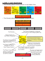
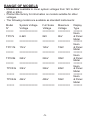
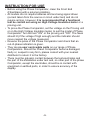
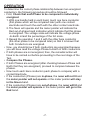
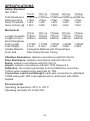
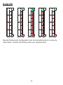
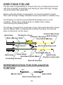
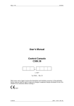
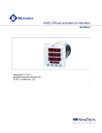
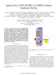
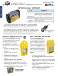
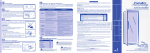
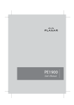
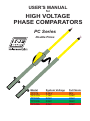
USER'S MANUAL
for
HIGH VOLTAGE
PHASE COMPARATORS
PC Series
Double Poles
Model
TPC7k
TPC11k
TPC22k
TPC33k
TPC44k
System Voltage
6.6kV
11kV
22kV
33kV
44kV
Full Scale
8kV
12kV
24kV
36kV
48kV
INDEX
PAGE
SAFETY RULES.............................................
1
GENERAL DESCRIPTION.............................
2
PRINCIPLE OF OPERATION.........................
2
PROVING THE PHASE COMPARATORS.....
3
LIMIT MARK...................................................
3
LABELS AND MARKING................................
4
RANGE OF MODELS.....................................
5
INSTRUCTION FOR USE..............................
6
OPERATION...................................................
7
SPECIFICATIONS..........................................
8
SCALES..........................................................
9
DIRECTIONS FOR USE................................. 10
TESTING FOR PHASING PRESENCE.......... 11
CARE AND MAINTENANCE..........................
12
LIMITED WARRANTY..................................... 13
NOTES............................................................ 14
SAFETY RULES
• Only Personnel who are fully trained in the use of High Voltage
Phase Comparators should use this equipment.
• Be aware that the system that it will be used on are powered from
high voltages which are lethal.
• Before use, ensure that the Phase Comparators and any
accessories are clean, free from cracks or deep scores, and are
properly secured together.
• Only the proper rated Phase Comparators must be used. Ensure
that the Phase Comparator is properly rated for the voltage of
the system under test.
• Test the operation of the Phase Comparator before and after
each test.
• Do not allow any part of the Phase Comparator except the contact
electrodes to come in contact with energized or earthed items.
• Safe Working distance must always be observed.
• Safety insulated Gloves and protective clothing and glasses
must be wear when using the Phase comparator.
• The Phase Comparator must only be handled by one person
only.
• Do not insert the Phase Comparator beyond its limit mark into
the apparatus under test. The Limit mark is the red band.
• The Phase Comparator should not be used as a synchronising
Device or a voltage detector.
• The Interconnecting lead/cord must not be allowed to come
within 100mm (10cm) of the hand guard and must not be
touched while testing.
• Before using the Phase Comparator in the testing of factory
assembled swtichgear, the manufacturer of the switchgear
must be consulted as the suitability of the Phase Comparator in
such testing.
• Always check for Phase Presence before testing between
Phases. Ensure that voltage is present on both phases
before testing between phases.
• The Phase Comparators are not to be subjected to a constant
voltage for a period longer than 1 minute in every five minutes.
-1-
GENERAL DESCRIPTION
• The range of high Voltage Phase Comparators have been designed
to comply and exceeds the requirements of VDE0681Part5.
• The Phase Comparators are double poles devices which are used
to determine the correct Phase Relationship between two
energized conductors of the Same nominal Voltage and
Frequency.
• Models are available to cover systems voltages from 1kV to 44kV
50/60Hz.
• For other systems voltage, please contact the factory.
• All models may be used indoor and outdoors in dry weather only.
PRINCIPLE OF OPERATION
• The PC range of Phase Comparators is a resistive devise which
comprise mainly of resistors, a neon and a panel meter. The Phase
Comparator draw current from the circuit or source under test.
• The Phase Comparator consist of two inter-connected poles (the
master pole with the panel meter and the slave pole).
• The Master pole carries the panel meter with the color coded scale
and the integral neon light indicator.
• The color coded scale indicates "in-phase/out-of-phase" band on
the scale. (Green = in-phase; Red=out-of-phase).
• The Neon light lit up when the voltage between the poles is greater
than ±1.2kV ±1.5kV.
• If two energized conductors are out-of-phase and a contact
electrode is touched onto each pole, current will flow between the
conductors through the resistors (resistors are inside the fiberglass
front end in each pole) in the poles and the interconnecting
lead/cord. This will cause the neon to lit and the panel meter's
indicator to move into the out-of-phase area (Red).
• If two energized conductors are in-phase and a contact electrode is
touched onto each pole, current will not flow between the
conductors through the resistors in the poles and the
interconnecting lead/cord. This should not cause the neon to lit and
the panel meter's indicator to move. The indicator will stay into the
in-phase area (Green).
• Ensure that voltage is present on both phases before testing
between phases.
-2-
PROVING THE PHASE COMPARATORS
• Before and after using a Phase Comparator and accessories, a
functional test should be performed on the Phase Comparator as
It is to be used on the source or circuit to test.
• A High Voltage Insulation tester can be used for this purpose.
• When using a High Voltage Insulation tester, the Phase
Comparator will indicate the voltage generated by that H.V.
Insulation tester.
• Please note that H.V. Insulation testers are generating DC voltage
and have polarity.
• The PC range of Phase Comparators are using a ½ bridge rectifier
and current only pass one way into the panel meter. However, the
neon must lit both ways.
• When proving with a DC source as with a H.V. Insulation tester,
the poles must be tested for both polarity to confirm that the panel
meter only show voltage in one way, but confirm that the neon
indicates both polarity.
• The reading on the High Voltage Insulation tester also indicate the
total value of the resistor chain and is also a good indication that
the circuit is still correct and in good condition (See specifications).
• A Proving Unit can also be used if a High Voltage Insulation
Meter is not available. The Proving unit does not indicate how
many mega ohms are in the front end or if the circuit is still in
good condition or not. The Proving unit only output a DC voltage
of 5kVdc.
LIMIT MARK
•
•
•
•
Each Phase Comparator has two poles.
Each pole has a front end which is in Fiberglass tubing.
Each pole has an Handle section.
At the junction between the handle section and the front end
section, there is a RED BAND which is the limit mark.
• By definition, this mark, or the Red Band, indicates the physical
limit to which the poles of the Phase Comparators may be
inserted between live components or may touch them.
-3-
LABELS AND MARKING
• The following labels must be present on the Master Pole.
TPC 7k
6.6kV
TPC 22k
22kV
TPC 11k
11kV
50/60Hz
TPC
TPC33k
33k
33kV
50/60Hz
50/60Hz
50/60Hz
50/60Hz
TPC 44k
44kV
50/60Hz
PHASE
PHASE
PHASE
PHASE
PHASE
PHASE
COMPARATOR COMPARATOR COMPARATOR COMPARATOR
COMPARATOR COMPARATOR
7kV
11kV
22kV
33kV
44kV
Climatic Class - Normal
Outdoor
Climatic Class - Normal
Outdoor
Climatic Class - Normal
Outdoor
Climatic
Climatic Class
Class -- Normal
Normal
Outdoor
Outdoor
Climatic Class - Normal
Outdoor
CONFORMS TO DIN VDE 0681/5
• The following labels must be present on BOTH Poles.
NOT FOR USE IN RAIN
CAN BE USED AS A VOLTAGE TESTER
6.6kV
11kV
22kV
33kV
44kV
DANGER: USE ON SYSTEMS UP TO
6.6kV ONLY AS PER INSTRUCTION MANUAL
DANGER: USE ON SYSTEMS UP TO
11kV ONLY AS PER INSTRUCTION MANUAL
DANGER: USE ON SYSTEMS UP TO
22kV ONLY AS PER INSTRUCTION MANUAL
DANGER: USE ON SYSTEMS UP TO
33kV ONLY AS PER INSTRUCTION MANUAL
DANGER: USE ON SYSTEMS UP TO
44kV ONLY AS PER INSTRUCTION MANUAL
The Phase Comparator is designed
to be used up to this voltage system only.
Part Number
Voltage System for
this Phase Comparator
TPC 11k
11kV
50/60Hz
The Phase Comparator will
operate over the frequency
range 50 to 60 Hz.
PHASE
COMPARATOR
11kV
Climatic Class - Normal
Outdoor
The Phase Comparator is
designed for use on
High Voltage Systems.
• Care must be taken to observe the attached labels, which must not be removed.
The labels warn of danger and to use only up to the rated voltage, as per
instruction manual. The Labels "Frequency Range", "Year of Manufacture","not to
be used in the rain", "not to be used as voltage tester" are self-explanatory and are
to be strictly Observed.
Read and Understand the
Instruction manual before
using the Phase Comparator.
The Phase Comparator is suitable
for use either indoor or outdoor in
dry condition
The user must keep hands
The Phase Comparator will
and all parts of the body
perform correctly over
behind the hand guard
the temperaturerange
to maintain safe
of -25°C to + 55°C.
WARNING
working distances.
STAY BEHIND HAND GUARD
-4-
RANGE OF MODELS
• Models are available to cover system voltages from 1kV to 44kV
@50 or 60Hz.
• Contact the factory for information on models suitable for other
voltages.
• The following models are available as standard instruments:
Model
N°
=====
System Voltage
Voltage
============
Full Scale
Voltage
========
Maximum
Voltage
========
TPC7k
6.6kV
8kV
9kV
=====
============
========
========
TPC11k
11kV
12kV
15kV
=====
============
========
========
TPC22k
22kV
24kV
30kV
=====
============
========
========
TPC33k
33kV
36kV
40kV
=====
============
========
========
TPC44k
44kV
48kV
55kV
=====
============
========
========
-5-
Display
Type
======
Neon
& Panel
Meter
======
Neon
& Panel
Meter
======
Neon
& Panel
Meter
======
Neon
& Panel
Meter
======
Neon
& Panel
Meter
======
INSTRUCTION FOR USE
• Before using the Phase Comparator, clean the Front End
(FiberGlass) with a polymer polishing.
• All models do not require batteries and are being signal driven
(current taken from the source or circuit under test) and do not
require arming. However, it is recommended that a functional
test be carried out using an High Voltage Insulation tester or a
proving unit.
• To prove the Phase Comparator, set the voltage on the Proving unit
or on the High Voltage Insulation tester, to suit the model of Phase
Comparator. Turn the test "ON" or the proving unit "ON". The Neon
should lit (if the voltage if high enough) and the indicator should
move nearest the voltage measured.
• Reverse the poles of the Phase Comparator and check that an
out-of-phase indication is given.
• They are no user serviceable parts on our range of Phase
Comparators. Should the Phase Comparator become damaged,
faulty or, suspect in any form, please consult with your nearest
distributor to return it to the factory.
• There must be galvanic contact between the test electrodes and
the part of the installation under test and, no other part of the phase
Comparator, except the electrodes, should be in contact with
energized or earthed parts, in order to ensure accuracy of the
display.
-6-
OPERATION
To determine the correct phase relationship between two energized
conductors, the following procedure should be followed:
• First, Check that each Phase to be compared is individually
energized.
1. With one handle held in each hand, touch one bare conductor
(first phase which will be compared later) with one contact
electrode and touch the earth with the other contact electrode.
2. The Neon will operate and the meter pointer will indicate the
Red out-of-phase band indication which indicate that this phase
is energized. The voltage scale will indicate the voltage phase
-to-Earth or/and the percentage of the full scale.
3. Repeat the operation 1 and 2 with the other bare conductor
(the other phase to be compared later) so that it is known that
both Conductors are energized.
• Now, you should know if both conductors are energized because
you will have read the voltage Phase-to-Earth of both conductors.
• If both phases are not energized, then, the remedial action will
have to be carried out before proceeding to the next stage of the
Test.
• Compare the Phases.
• If both Phases are energized (after checking between Phase and
Earth that they are energized ) proceed to compare between the
phases.
• Now touch each bare conductor (each phase to compare) with a
contact Electrode.
• If the conductors (Phases) are in-phase, the neon will not lit and
the meter pointer will not operate or the meter pointer will stay
in the Green band.
• If the conductors (Phases) are out-of-phase, the neon will lit and
the meter pointer will operate or the meter pointer will go in the
Red band.
-7-
SPECIFICATIONS
Safety Standard
IEC 61481
TPC7k
Total Resistance
Response time
Neon Threshold
Neon Lit Fully @
TPC11k
TPC22k
TPC33k
TPC44k
4.48M ohm 6.78M ohm 10.82M ohm19.68M ohm26.8M ohm
<1Sec
1.2kV
1.5kV
<1Sec
1.2kV
1.5kV
<1Sec
1.2kV
1.5kV
<1Sec
1.2kV
1.5kV
<1Sec
1.2kV
1.5kV
TPC7k
TPC11k
TPC22k
TPC33k
TPC44k
775mm
400mm
775mm
400mm
775mm
500mm
775mm
665mm
775mm
820mm
1.175M 1.175M 1.275M 1.440M
2.1kG
2.1kG
2.2kG
2.4kG
Composite Material with Polyurethane
Fiber Glass Wound Tubing
1.595M
2.5kG
Mechanical
Lenght of Handle
Lenght of Front
End (Fiberglass)
Total Lenght
Total Weight
Handle Material
Front End
Vibration Resistance: tested in accordance with IEC 68-2-6
Drop Resistance: tested in accordance with IEC 68-2-32
Bump: tested in accordance with IEC 68-2-2
Impact: tested in accordance with IEC 1010 Clause 8.2
Deflection: the contact electrodes must not deflect by more than
150mm when loaded at the electrode by 10N.
Connection Lead.Cord Strenght: each pole connection to withstand
10000 swing with 10N Load applied and a vertical pull with 200N
applied.
Environmental
Operating temperature:-25°C to +55°C
Operating Humidity: 20 to 96% RH.
-8-
SCALES
0
0
%
50
%
50
5.3
TPC 22k
32
KV
TPC 11k
KV
KV
KV
KV
TPC 7k
24
24
100
16
%
50
16
12
100
12
%
50
8
8
100
8
0
0
AC
%
50
4
0
0
AC
2.7
0
0
AC
0
AC
AC
0
36
100
TPC 33k
48
100
TPC 44k
Special Scales and configuration can be manufactured on a case by
case basis. Contact the factory with your requirements.
-9-
DIRECTIONS FOR USE
It is the user's responsibility to ensure that only competent personnel,
with the necessary knowledge and training to work with high voltage,
use and handle this equipment.
Before using the Phase Comparators, it is recommended to check
them with an High Voltage Insulation tester (if possible a variable one).
For Phasing, it must be ensured that both feeders are in a live
condition, of the same voltage and in a stable state, before
commencing the phasing tests.
The Phase Comparators comprises of two interconnected parts; these
are the Master Stick, containing the indicator housing. The second
stick is referred to as the slave.
Contact Electrode
Protective Cover
Indicator Housing (Split Probe)
Main (Master) Stick
Front End (Master)
Hand Grip
Hand Guard
Interconnecting Lead
Front End (Slave)
Slave
Stick
Split Probe
Hand Grip
Red Band (Limit Mark)
(Contact electrode)
Insulating element
Resistif element
REPRESENTATION FOR EXPLANATION
PURPOSE
M-S
S-S
Master Stick
Slave Stick
Interconnecting Lead
-10-
TESTING FOR PHASE PRESENCE
Before doing the Phase Comparison test, you must ensure that the
feeders to be compared are live.
FEEDER "1"
Phase "A"
Phase "C"
TESTING FOR PHASING
No Indication - Neon OFF (does not lit) = IN PHASE
FEEDER "1"
Phase "A"
M-S
S-S
FEEDER "2"
Phase "A"
Phase "B"
Phase "B"
Phase "C"
Phase "C"
Indication - Neon ON (does lit) = OUT OF PHASE
FEEDER "1"
Phase "A"
M-S
S-S
FEEDER "2"
Phase "C"
Phase "B"
Phase "B"
Phase "C"
Phase "A"
Note that the links must be arranged so that the phases are
Connected in Phase, as indicated by the dotted lines.
Do Not Use Phasing Sticks unless you have been fully trained
In High Voltage work and understand the system fully.
-11-
S-S
S-S
Earth
To Check Phase Presence,
measure the Voltage between
Phase and Earth. The result
will confirm that voltage
is present and that the
Earth
amplitude are the same.
M-S
M-S
Phase "B"
FEEDER "2"
Example: Preparing to
Phase "A"
Compare two Phases
From different feeders
Check that both phases to Phase "B"
be compared are Live and
have the Same amplitude. Phase "C"
CARE AND MAINTENANCE
• Storage: The Phase Comparator and it's accessories should be
stored in the proprietary carrying case/bag when not in use.
• Transporting: When the equipment is in transit it should be stored
in its carrying case/bag. Whilst the equipment has been designed
for field use it should not be subjected to excessive bumps and
shocks.
• Cleanliness: Dirt can cause surface tracking and it's therefore
necessary to keep the Phase Comparator and its accessories clean
by washing them in mild detergent solution. All part should be
cleaned with the appropriate liquid.
• Mechanical Damage: If surface scratches or dents can easily be
seen by the naked eye, then the equipment should be returned to
the factory of your nearest distributor for repairs since these
blemishes act as traps for dirt and moisture. Mechanical damage
would also necessitate the return of the equipment to the
manufacturer.
• Recelebration and Proof Testing: Every twelve months the Phase
Comparator and it's accessories should be rechecked. This would
include checking the threshold level of the neon, voltage proof
testing in factory or accredited laboratory and pressure testing of
the panel meter housing.
Please note that there are no internal user replaceable parts.
The Phase comparator must always be clean and dry before use
and during use. Please store the Phase Comparator in a dry
Place.
-12-
LIMITED WARRANTY
We warrant the product manufactured by us to be free from
defective material or factory workmanship and agree to repair or
replace this product which, under normal use and service, disclose
the defect to be the fault of our manufacturing, with no charge for
parts and service.
If we are unable to repair or replace this product, we will make a full
refund of the purchase price. Consult the user's manual for proper
instruction regarding use of this instrument. Our obligation under this
warranty is limited to repairing, replacing or making refund of this
test equipment which proves to be defective within forty eight
months from the date of purchase.
This warranty does not apply to any of our products which have
been repaired or altered by unauthorized persons in any way so as,
in our sole judgement, to injure their stability or reliability, or which
have been subject to misuse, abuse, misapplication, negligence or
accident or which have had the serial numbers altered, defaced or
removed.
All warranties implied by law are hereby limited to a period of fourty
eight months, and the provisions of the warranty are expressly in
lieu of any other warranties expressed or implied.
The purchaser agrees to assume all liability for any damages or
bodily injury which may result from the use or misuse of the product
by the purchaser, or it's user, his employees, or others, and the
remedies provided for in this warranty are expressly in lieu of any
other liability we may have including incidental or consequential
damages.
We reserve the right to discontinue models at any time, or change
specification, price or design, without notice and without incuring
Any obligation.
-13-
NOTES
We Exceeded the safety specifications wherever possible. However,
we can't be held liable for misuse or bad manipulation.
We simplified the Phase Comparators by not having any parts to
assemble on site. There is no user serviceable parts or user
assembled part in our Phase Comparators.
Only the tip (contact electrode) has to be screwed on the Front end
of each pole. They generally do not need to be removed by the user.
For other kind of tips and contact electrodes, contact the factory or
you nearest distributor.
Getting regular training on your High Voltage equipment and on the
electrical network / grid you are working on is a good practice and
will help in keeping you safe.
Always make a sketch before proceeding with testing High Voltage
and ensure you are fully in control of the testing and understand
Fully what is going on. Failure to do so can result in fatal accidents.
-14-