1
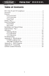
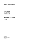
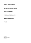
Oakley Sound Systems
Human Voice Module
PCB Issue 1
Builder's Guide
V1.0.5
Tony Allgood
Oakley Sound Systems
CARLISLE
United Kingdom
Introduction
This is the Builder's Guide for the issue 1 Human Voice Module (HVM) from Oakley Sound.
This document contains a basic introduction to the circuit board and a full parts list for the
components needed to populate the board or boards.
For the User Manual, which contains an overview of the unit and goes into some detail
regarding the operation of the module, please visit the main project webpage at:
http://www.oakleysound.com/hvm.htm
For general information regarding where to get parts and suggested part numbers please see
our useful Parts Guide at the project webpage or http://www.oakleysound.com/parts.pdf.
For general information on how to build our modules, including circuit board population,
mounting front panel components and making up board interconnects please see our generic
Construction Guide at the project webpage or http://www.oakleysound.com/construct.pdf.
This is an early version of the documentation. If you do find any errors, even silly little ones,
please do let me know either directly by e-mail or via the forum.
A completed issue 1 HVM circuit board awaiting its case.
2
The Oakley Sound Human Voice Module
The HVM does not have any built in power supply. It is expected that the circuit board be
powered from a regulated split supply of +/-12V to +/-17V. Power is admitted onto the board
via a four way 0.156” (2.96mm) header of MTA or KK type.
The module is designed to be powered by our own Rack Power Supply Unit (RPSU) or any
other split rail compatible supply such as the Oakley PSU. The benefits of using the RPSU is
its small size and ability to take a variety of different AC power sources. Because of the
inherent dangers of using a component level mains transformer in your project I recommend
that you use an external low voltage AC source such as that obtained from a wallwart or line
lump. The RPSU can then be fed from a low voltage alternating current supply so all the high
voltages are kept inside the wallwart or line lump. The User Manual for the RPSU will go into
more detail of the various options for powering your unit. A single RPSU should be capable of
driving both the HVM and SE330 should both projects be built into the same case.
The board size is 198mm (width) x 131mm (depth). Power consumption of the HVM, with no
audio passing through it, is +/-80mA at +/-15V.
The power header on the HVM board. This is a 0.156” (3.96mm) Molex KK. This is similar to the
MTA156 type connector that we normally use on our MOTM compatible modules but the two are not
interchangeable. However, the KK is cheaper and only requires a cheap crimper to make the leads.
3
Parts List
For general information regarding where to get parts and suggested part numbers please see
our useful Parts Guide at the project webpage or http://www.oakleysound.com/parts.pdf.
The components are grouped into values, the order of the component names is of no particular
consequence.
A quick note on European part descriptions. R is shorthand for ohm. K is shorthand for kiloohm. R is shorthand for ohm. So 22R is 22 ohm, 1K5 is 1,500 ohms or 1.5 kilohms. For
capacitors: 1uF = one microfarad = 1000nF = one thousand nanofarad.
To prevent loss of the small ‘.’ as the decimal point, a convention of inserting the unit in its
place is used. eg. 4R7 is a 4.7 ohm, 4K7 is a 4700 ohm resistor, 6n8 is a 6.8 nF capacitor.
Resistors
All resistors 5% or better 0.25W types. Those items marked with 1% need to be 1% metal
film (or better) 0.25W metal film resistors. For the sake of clarity it is recommended to make
all resistors 1% metal film types.
47R
110R
220R
220R 1%
1K
1K2
2K2
3K3
4K7
10K
10K 1%
15K
22K
22K 1%
27K
33K
68K
100K
100K 1%
180K
220K
330K
390K
470K
R70, R69
R94
R23, R20
R107, R106, R34, R35
R74, R103, R66, R73, R108, R38, R100, R44, R41
R28, R25, R83, R51, R89, R64, R32
R16, R61
R113
R93, R105
R77, R79, R110, R60, R78, R67, R49, R80, R17, R48, R65, R109,
R68, R104, R96, R95, R81, R47
R1, R4, R11, R14
R3, R6
R91, R92, R18, R62
R7, R8, R9, R10
R37, R99, R40, R72, R76, R102, R43
R12, R5, R2, R15
R55, R87, R84, R86, R54, R53, R85
R90, R13, R63, R19, R21, R22, R46, R97
R111, R112
R71, R101, R39, R75, R98, R42, R36
R57, R27, R58, R50, R26, R59, R88, R31, R45, R24, R56, R82
R30, R33
R52
R29
4
10K x 8 resistor pack. 9 pin single in line (SIL) package
RN1
Capacitors
100nF axial multilayer ceramic
C25, C27, C47, C49, C76, C23, C53, C39, C6, C7, C9,
C73, C28, C54, C38, C5, C8, C87, C10, C72, C88,
C70, C52, C48, C37, C71, C51, C36, C50, C75, C74,
C24, C77, C26
33pF 2.5mm C0G ceramic
100pF 2.5mm C0G ceramic
470pF 2.5mm C0G ceramic
C40, C84, C85
C2, C14
C13
1n5 polyester
3n3 polyester
3n9 polyester**
8n2 polyester**
12nF polyester
15nF polyester
18nF polyester
47nF polyester
56nF polyester
100nF polyester
680nF polyester
1uF polyester
C61, C62
C35, C22, C34, C21
C58, C44, C60, C46
C81, C83, C66, C68
C63, C64, C78, C79
C3
C55, C56, C42, C41
C33, C19, C20, C32
C31, C30, C18, C17, C12
C1
C16, C15, C69, C4
C89, C29, C11
10uF, 35V electrolytic
10uF, 16V non polarised* elect
C91, C92
C86, C90
* Non polarised capacitors can sometimes be called bipolar. Unlike ordinary polarised
electrolytic capacitors they can be put into the board any way around.
** Both 8n2 and 3n9 may be difficult to find from your normal parts supplier. There are places
on Ebay that sell both values, usually the old green cased 'mylar' capacitors, and these seem
easy enough to get. However, provision on the board has been made to substitute two smaller
value capacitors instead which when combined make up a close approximation of the required
value.
1n5 polyester
6n8 polyester
C68, C66, C83, C81
C67, C65, C82, C80
560pF 5mm ceramic or polystyrene C46, C44, C60, C58
3n3 polyester
C45, C43, C59, C57
Discrete Semiconductors
1N4004 diode
Green or yellow 3mm LED
D1, D2
ON
5
Integrated Circuits
OPA2134PA
TL072
U1, U3, U8, U12, U14, U17
U2, U4, U5, U6, U7, U9, U10, U11, U13, U15, U16
IC sockets are recommended. You need seventeen 8-pin DIL sockets.
Pots
All pots 16mm Alpha or Alps types.
10K log dual gang
10K reverse log
47K linear
FREQUENCY
Q
LEVEL, OUTPUT, GAIN, WET/DRY
Six Alpha pot brackets.
Six knobs to suit.
Switches
SPDT toggle PCB mounted
DPDT toggle PCB mounted
CHO/VOX, UPR/LWR
FOOTAGE
Interconnects
4 way 3.96mm Molex KK or MTA header
2 way 0.1” Molex KK or MTA header
3 way 0.1” Molex KK or MTA header
PSU
INPUT
OUT
Other interconnects may be required if you intend to use the HVM differently to the suggested
design.
Wire Links
These are to be fitted if you are building the suggested design. Use a small piece of
uninsulated wire like a resistor wire clipping.
Link out LK1. This connects the pre-amp output to the chorus filter network.
Link pin 2 of FBO to pin 2 of EQI. Pin 2 is the round pin on each header. This connects the
output of the wet/dry balance circuit to the input of the parametric equaliser.
6
A close up of the resistor network. This is eight resistors in one package manufactured so that one end of
all the resistors are tied to one pin – usually labelled with dot or a line.
A close up of the wire link that joins the FBO and EQI headers
7
Modifications
The HVM is configured to work well with line level signals like those coming from a mixing
desk's auxiliary outputs. It can also be plugged into most synthesiser outputs, including
modulars, with no issues. However, you may wish to use the HVM on an output that is
weaker than normal. Like, for example, an older machine like the Logan String Melody. In this
case it is a good idea to increase the input sensitivity.
The easiest way of doing this is to change the value of R6. This sets the gain of the post input
level amplifier. Doubling the value of R6, to say 33K, will double the sensitivity of the input.
If you find the volume level too low when used in the Vox mode then you can increase the
value of R81. Currently it's at 10K. Increasing it to 22K will double the gain of the filter
network summing amp, based around U13a, and produce an increase in Vox volume.
However, I have chosen 10K for a reason; the Vox mode's filter networks do produce some
very large increases in signal level at certain specific frequencies which may distort the signal.
Feel free to experiment though.
If you do make some interesting changes to the circuit do let the Oakley community know via
our friendly online forum at Muffwigglers. I, for one, am always interested to hear what
people do with their Oakley Sound projects.
8
Mounting the Pots, LEDs and Switches
If you are using the recommended Alpha pots, then they can support the PCB with specially
manufactured pot brackets. You may not normally need any further support for the board
although I do tend to use the rear pair of mounting holes and attach these to threaded hex
spacers which then attach to the bottom panel of the case. When constructing the board, fit
the pot brackets to the pots by the nuts and washers supplied with the pots. Now fit them into
the appropriate holes in the PCB. But only solder the three, or six, pins that connect to the
pot. Do not solder the pot bracket at this stage. When you have soldered all the pots you can
fit the board to your front panel. Position the PCB at right angles to the panel, the pot’s own
pins will hold it fairly rigid for now. Then you can solder each of the brackets. This will give
you a very strong support and not stress the pot connections.
The Alpha pots are labelled with an A, B or C suffix. For example: 50KB or 10KC. Alpha and
ALPS use the key; A = log, B = linear and C = reverse log. So a 47KB is a 50 kilohm linear
pot.
The single board mounted LED must be fitted carefully if you are using the directly mounted
technique. Although this sounds fiddly, it's actually quite easy and it reduces wiring,
interference and possible errors.
A close up of the LED. This should light up when the power is on. You can chose any colour you wish but
I tend to like either green or yellow.
Remove the front panel so that you just have the board again. Get the LED and find the
cathode. Make sure the cathode of the LED will go into the square pad, pin 1, on the board.
Carefully bend the LED’s legs at a point 6mm away from the plastic body of the LED. The
legs should be bent by 90 degrees so that the legs are pointing straight down. Check to see if
they fit into the board. The bottom of the LED’s body should fit just flush to the board edge.
Fit the LED to the board but do not solder it in at this stage. Let its legs poke through, there’s
no need to cut them down yet. Now fit the front panel again to the board and tighten the pot
9
nuts. You should find that the board now fits snugly into position and the LED should be just
poking out of its hole neatly, albeit loosely. Align the LED if it isn't quite straight and then
solder it, trimming its leads nice and short afterwards.
The three switches. These are made by Multicomp (part numbers 1MS1T2B4M7RE for the two SPDT and
1MD1T2B4M7RE for the single DPDT.)
With panel removed once again, you can now fit the switches. The PCB mountable switches
should fit tightly into their respective holes on the board. Indeed, they'll probably work for
short time without soldering them so don't forget to do so.
Make sure the switch body is flat against the board. Now refit the front panel and make sure
the round switch barrel fits into its hole in the front panel. Now solder all the pins on each of
the switches including the two securing pins to the front.
That completes the soldering of the front panel components.
10
Power Supply
Power is admitted onto the board using the usual Oakley power system. That is a single four
way 0.156” (3.96mm) MTA or Molex KK header. For the rack projects I am recommending
the Molex system over the MTA simply because the tool needed to make the interconnects is
much cheaper. It is also possible to solder the crimp terminals used in the KK system. It is, of
course, quite possible to solder your power leads straight onto the board. The board is
protected against reverse polarity with a couple of diodes. Note that these diodes work by
shorting out your power supply in the event of a reversal. Because of this they should not be
relied on if the reversal continues for a long time as this will stress both the diodes and the
power supply. The diodes are simply there to save the board's ICs from certain death in the
event of the power being inadvertently reversed during testing. There is no overvoltage
protection to be careful not to put anything over +/-17V into the board.
The pin out for the power connector, PSU:
Pin 1
Pin 2
Pin 3
Pin 4
+12V to +17V
Ground (0V)
Ground (0V)
-12V to -17V
Pin 1 is indicated by the little diagonal on the header's legend.
Both ground connections need not be connected to your power supply. However, you do
most certainly need at least one of them – either pin 2 or pin 3 will do if you using only one
connection.
A special compact low voltage supply has been made for this, and other Oakley rack projects,
in the form of the Oakley RPSU. You don't have to use this as any decent split rail supply will
do but it is an easy build and is flexible enough to suit most builders' needs. Please see the
RPSU Builder's Guide and User Manual for more details.
11
Inputs and Ouputs
If you are building the suggested design then you have only one input and one output. Both
input and output are balanced and you should use TRS jack sockets. TRS, tip-ring-sleeve,
sockets are ones with three poles and are also used for headphone outputs.
Even though both input and outputs are balanced they are still compatible with unbalanced
signals. This means you can plug ordinary two pole mono jacks into the TRS sockets and the
unit will work as expected.
Audio projects should really be built into metal cases to prevent interference and because of
this we now face a bit of a conundrum. Ideally, balanced input and output sockets should be
grounded to the case. If you have internal mains transformer then the case will be grounded
via the power supply so this will ground the socket and any connecting cables. But this only
works if your sockets have a metal frame and can be guaranteed to make a permanent
electrical connection to the casing when they are tightened up. It also means that your PSU
must be grounding the case directly which, unlike with the internal mains transformer, is not
what I recommend when using an external wall wart.
Therefore I prefer to use plastic framed chassis mounted sockets for my rack projects. This
allows the case to be grounded via the power supply and keep the sleeve terminals of all the
sockets locally isolated from the case. Grounding the sockets must therefore be done via a
short wire link back to either the PSU's main ground star point (which is not so easily done on
the RPSU if both four way headers are being used) or the main HVM PCB.
Input Socket
The two way header, named INPUT, should be wired so that pin 1 goes to the ring of the
input socket and pin 2 goes to the tip. The sleeve, or ground, of the input socket connects to
the sleeve of the output socket.
Output Socket
The three way header, named OUT, should be wired so that pin 1 connects to the tip of the
output socket and pin 3 goes to the ring. The sleeve, or ground, of the output socket connects
to pin 2 of the OUT header.
12
Other I/O Options
The HVM is designed to be very flexible. It has four main circuit parts and all are available
with individual inputs and outputs should you wish to use them. I cannot go into every
possible combination since I will leave this to the builder of the unit to decide. However, I will
give a quick run down of what is available and a description of the slightly cryptic
nomenclature of the headers on the board. It is advisable that if you are planning on some
cunning interfacing that you are able to read the schematic well.
The four main circuit sections are pre-amplifier, chorus filter network, vox filter network and
parametric equaliser.
1. Pre-amplifier.
Input via the balanced input of the header INPUT. Pin 2 is hot (tip) and pin 1 is cold (ring).
Output via pin 2 (middle pad) of the UPR/LWR switch. The output is also hardwired to the
wet/dry mixer pot's dry end. Thus the pre-amplifier's balanced output is also available via the
FBO (filter bank output) header. Pin 2 is hot (tip) and pin1 is cold (ring).
2. Chorus filter network
Input via the CHI (chorus input) header. Pin 2 is signal, pin1 is ground. But this can be, and is
in the suggested design, connected directly to the pre-amp output via LK1. If you want to use
CHI as a separate input you must remove LK1.
Output via the CHO (chorus output) header. Pin 2 is the signal, pin 1 is ground.
3. Vox filter network
Input via one of four inputs, F4U, M8U, M4L & M8L. Each of these inputs represent the
connection that was made on the original VP-330. F4U being Female 4” Upper, M8L being
Male 8” lower, etc. If you have an old string machine with a split keyboard and two available
footages these inputs are the ones to use. It is these I used on my own RS-101 upgrade
project.
The four inputs are accessed by their own headers. Again, pin 2 is the signal input and pin 1 is
ground.
The output of the Vox filter network is available from the VOX header. Pin 2 being the signal
and pin 1 being ground.
Alternatively, the outputs from both Vox and Chorus filter networks can be obtained from the
wet/dry mixer output, header FBO. The CHO/VOX switch will then determine the choice of
filter heard and the wet/dry pot will also allow for the pre-amplifier's output to be mixed in.
13
4. Parametric equaliser
Input is available via the EQI (equaliser input) header. Pin 2 is the signal, pin 1 is ground.
Output is available via the HVM's main balanced output, OUT. Pin 1 is hot (tip), pin 2 is
ground (sleeve) and pin 3 is cold (ring).
Final Comments
If you have any problems with the module, an excellent source of support is the Oakley Sound
Forum at Muffwiggler.com. Paul Darlow and I are on this group, as well as many other users
and builders of Oakley modules.
I'd love to hear about what you have done with your module. Please do post pictures of your
finished module at the Oakley Sound forum on Muffwigglers.
And if you can't get your project to work, then Oakley Sound Systems are able to offer a 'get
you working' service. If you wish to take up this service please e-mail me, Tony Allgood, at
my contact e-mail address found on the website. I can service either fully populated PCBs or
whole modules. You will be charged for all postage costs, any parts used and my time at
25GBP per hour. Most faults can be found and fixed within one hour, and I normally return
modules within a week. The minimum charge is 25GBP plus return postage costs.
If you have a comment about this user guide, or have a found a mistake in it, then please do let
me know. But please do not contact me or Paul Darlow directly with questions about sourcing
components or general fault finding. Honestly, we would love to help but we do not have the
time to help everyone individually by e-mail.
Last but not least, can I say a big thank you to all of you who helped and inspired me. Thanks
especially to all those nice people on Muff's Forum and the Synth-diy and Analogue Heaven
mailing lists.
Tony Allgood at Oakley Sound
Cumbria, UK
© March 2013 - updated August 2013
No part of this document may be copied by whatever means without my permission.
14