1
User Manual V2.48
SF6 AREACHECK P2 – The SF6 Room Monitor
Advanced Gas Sensing Technologies
sf6test.com
User Manual SF6 AREACHECK P2 Room Monitor V2.48 - Page 2
Table of Contents
Declaration of Conformity ....................................... 3
Installation .............................................................. 4
Location ............................................................................................ 4
Wiring ............................................................................................... 5
Network diagram ............................................................................... 6
Operation................................................................. 7
Auto-Zero at Startup .......................................................................... 7
Measuring Interval ............................................................................. 7
Indicator Lights ................................................................................. 8
Lamp Test and Manual Reset .............................................................. 8
Configuration via the PC interface ........................... 9
Connecting to the Host Computer........................................................ 9
User Parameters ................................................................................ 9
Changing the Sensor Unit ...................................... 10
O2 Sensor .............................................................. 11
Functionality .................................................................................... 11
Physical location .............................................................................. 11
Sensor Type .................................................................................... 11
Sensor Lifetime................................................................................ 11
User Interface ................................................................................. 11
Safety ............................................................................................. 11
Technical Data ....................................................... 12
Notes ..................................................................... 13
Advanced Gas Sensing Technologies
sf6test.com
User Manual SF6 AREACHECK P2 Room Monitor V2.48 - Page 3
Declaration of Conformity
Name und Adresse des Herstellers / Manufacture´s name and address / Nom et adresse du Fabricant
abricant
ISM Deutschland GmbH, Laubach 30, D-40822 Mettmann, Germany
Die ISM Deutschland GmbH bescheinigt die Konformität für das Produkt / The ISM Deutschland GmbH declares conformity of
the product / ISM Deutschland GmbH dérclare la conformite du produit
Bezeichnung / Product name :
SF6-Raumluftmonitor / SF6-Roommonitor
Roommonitor
Typ / Type / Type:
SF6 AREACHECK P2
Mit den folgenden Bestimmungen / with applicable regulations / avec les directives suivantes
EMV Richtlinie 89/336/EWG ergänzt durch 91/263/EWG, 92/31/EWG
EMC Drective 89/336/EEC amended by 91/263/EWG, 92/31/EEC
Directive EMC 89/336/CEE amendée par 91/263/EWG, 92/31/CEE
Niederspannungsrichtlinie 73/23/EWG ergänzt durch 93/68/EWG
Low-Voltage
Voltage Equipment Directive 73/23/EEC amended by 93/68/EEC
Directive des equipements basse tension 73/23/CEE amendée par 93/68/CEE
Angewendete harmonisierte Normen / Harmonized standards applied / Normes harmonisées utilisáes
Sicherheit / Safety / Sécurité
EN 61010-1 : 1993 / IEC (CEI) 1010--1 : 1990 A 1 : 1992 / VDE 0411: 1994
Überspannungskategorie / Overvoltage category / Catégorie de surtension: II
Verschmutzungsgrad / Degree of pollution / Degré de pollution: 2
Elektromagnetische Verträglichkeit / Electromagnetic compatibility / Compatibilité electromagnétique
EN 50082-2: 1995 / VDE 0839 T82-2
ENV 50140 : 1993 / IEC (CEI) 1001-4
4-3 : 1995 / VDE 0847 T3
ENV 50141 : 1993 / IEC (CEI) 1000-4
4-6 / VDE 0843 / 6
ENV 61000-4,2 : 1995 / IEC (CEI) 1000-4-2
1000
: 1995 / VDE 0847 T4-2:
Prüfschärfe /Level / Niveau = 2
EN 61000-4-4: 1995 / IEC
EC (CEI) 1000-4-4:
1000
1995 / VDE 0847 T4-4:
Prüfschärfe /Level / Niveau = 3
EN 50081-1 : 1992 / EN 55011 : 1991 / CISPR11 : 1991 / VDE0875 T11 : 1992
Gruppe / group / groupe = 1, Klasse / Class / Classe = B
Datum / Date / Date
01.08.2005
Unterschrift / Signature / Signatur
Hr. Becker – Technical Director
Advanced Gas Sensing Technologies
sf6test.com
User Manual SF6 AREACHECK P2 Room Monitor V2.48 - Page 4
Installation
Location
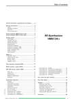
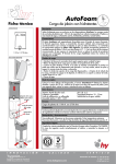
SF6 AREACHECK P2 is designed for indoor wall mounting. Since SF6 tends to sink towards the ground
in undisturbed air, we suggest to place it approx. 50 … 60 cm above ground level.
LED Status
Display
Run / Test / Reset
Key switch
Audible
Alarm
Sample
Intake
Sample
Exhaust
SmartSensor Module
Advanced Gas Sensing Technologies
sf6test.com
User Manual SF6 AREACHECK P2 Room Monitor V2.48 - Page 5
Wiring
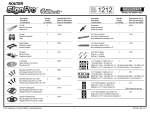
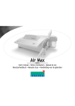
Mains power connects to the orange clamp block, according to the designation printed on the PCB
near each clamp.
For an optional audible and/or visible alarm device, a voltage free switchover relay output is supplied.
It is available on the blue 3 position clamp block in the middle. Contacts are, from left to right: N.O. /
COM / N.C.
During normal operation, COM connects to N.O. During an alarm or error condition, COM disconnects
from N.O. and switches over to N.C. The same applies in case of power failure, and whenever the
instrument is taken into setup mode via the host computer interface via the RS232 connector.
The leftmost 6 position clamp block is provided for network operation. Physically, the network follows
RS485 standards and hence has three wires named A, B, and GND. Their positions are marked on the
PCB next to the clamps. They must be wired to the corresponding pins on the SF6
NETWORKCONTROLLER P2NC. Double clamps are provided for each wire for easy "daisy chaining" of
several instruments.
RS 485 daisy chain PIN B
RS 485 daisy chain PIN A
RS 485 daisy chain PIN GND
Supply Voltage “N”
Supply Voltage “L1”
Supply Voltage “Earth”
RS 232 Connector
Alarm Relay PIN “Normally Closed”
Alarm Relay PIN “Common”
Alarm Relay PIN “Normally Open”
Advanced Gas Sensing Technologies
sf6test.com
User Manual SF6 AREACHECK P2 Room Monitor V2.48 - Page 6
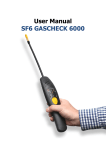
Network diagram
12
3
2
1
wiring detail
GND
A
B
Advanced Gas Sensing Technologies
sf6test.com
User Manual SF6 AREACHECK P2 Room Monitor V2.48 - Page 7
Operation
Auto-Zero at Startup
To precisely determine SF6 concentration, SF6 AREACHECK P2 requires a reference value representing
clean air. This reference value is taken and stored whenever the instrument is powered up or reset.
You should therefore make sure that power up takes place under clean air conditions.
A fresh reference value is also taken after manual reset via the key switch. Therefore, after each
manual reset, the instrument will temporarily only respond to SF6 concentrations exceeding the level
that was present at the time of manual reset. This will avoid the next measuring cycle to trigger an
undesired, new alarm. The reference value will auto-adapt to falling SF6 concentrations, so after once
meeting a clean air condition, SF6 AREACHECK P2 will automatically return to full sensitivity.
Since a reset is also performed when the instrument is taken into setup mode via the host computer
interface, the above also applies in this case.
After Power up or reset, the first measuring cycle starts immediately, beginning with the fan run time.
Measuring Interval
Since SF6 AREACHECK P2 is designed to determine slowly changing concentrations, it samples the air
at a fixed time interval rather than measuring continuously. This feature minimizes the amount of air
per time that passes the instrument’s intake system, thus extending its service life.
Via the measuring time interval, it is possible to perfectly adapt the instrument to the actual
application. For monitoring generally unattended spaces, a long time interval should be selected, while
in the working area a shorter interval is suggested.
SF6 AREACHECK P2 comes with a factory set measuring interval of 30 minutes, which is the suggested
starting point for most applications.
Advanced Gas Sensing Technologies
sf6test.com
User Manual SF6 AREACHECK P2 Room Monitor V2.48 - Page 8
Indicator Lights
6 LEDs on the instrument’s front panel represent its state as follows:
Placement of LEDs:
RUN
This light acts as a life sign to
confirm the SF6 AREACHECK P2 is
in operation. As long as no internal
error condition is met, it will blink
at all times. During the actual SF6
measurement (normally, this phase
is very short), it will blink at a
faster rate.
Should this lamp stop blinking,
an internal error has occurred.
ALARM
This light will be permanently on if the last measuring cycle has determined a SF6 concentration above
the selected alarm threshold.
In case of an internal error state, it will blink quickly.
The instrument’s internal audible alarm works in parallel with this lamp.
500 / 1000 / 1500 / 2000 [ppm]
These 4 yellow lamps reflect the last sampling period’s result in terms of alarm levels as designated.
On instruments equipped with the optional oxygen sensor, these lights have the following additional
functions:
•
The two leftmost LEDs (500+1000ppm) will blink when an oxygen concentration below the
lower alarm threshold of 16% is present.
•
The two rightmost LEDs (1500+2000ppm) will blink when an oxygen concentration above
the upper alarm threshold of 25% is present.
Lamp Test and Manual Reset
When the key switch is turned to the spring return "TEST" position, all lamps, the internal audible
alarm and the optional external alarm device will turn on until the key switch is released.
When released, a pending alarm condition is cleared.
NOTE: An error condition will NOT be cleared!
When the key switch is turned and released twice within 2 seconds, a system reset is performed
which also clears any pending alarm and error conditions, and logs a fresh reference value.
Advanced Gas Sensing Technologies
sf6test.com
User Manual SF6 AREACHECK P2 Room Monitor V2.48 - Page 9
Configuration via the PC interface
Connecting to the Host Computer
Parameter modification in stand-alone operation is done exclusively through the host computer
interface. This has the clear advantage that any unintended or unauthorised fiddling is discouraged.
The user parameters described in the following
are relevant for stand alone operation only. In
network operation, parameters received from
the network base unit will take precedence.
The host computer interface follows RS232
standards. A special interface cable connects
to the 3 position plug, which is found between
the two blue clamp blocks.
The lamp next to the plug indicates the
presence of valid RS232 levels from the host.
It will be lit when the host is on and correctly
connected.
On the host computer, a standard terminal
program is used to talk to the SF6 AREACHECK
P2. A suitable program called "Hyper Termina"
is a standard Microsoft Windows component and by default present in most installations. Optionally,
any other terminal software will work.
Set up the terminal program for the following parameters: 9600 baud, 8 data bits, no parity, 1 stop bit.
This is a standard configuration also known as "9600-8-N-1". Further, select "none" for the handshake
protocol, and "TTY" as emulation if available. The option "append CR" for received lines should be
checked for a more readable screen output. For your convenience, we will be pleased to send you a
predefined configuration file for "Hyper Terminal" which will perform all relevant settings for you.
Note:
While the PC interface is connected, the instrument will talk to the host computer only and no longer
communicate over the network. When present, an SF6 NETWORK CONTROLLER P2NC will see this
station as "OFFLINE" and issue an alarm accordingly.
User Parameters
User adjustable parameters are the time interval between each two samples ("Scan period") and the
alarm level. To activate the setup, from the terminal first send a line feed, then the instruction "TtS",
followed by another carriage return. A choice menu with the following options will then be presented:
<1> Scan period
<2> Alarm level
<3> Exit and resume operation
Just type the corresponding number to invoke the desired option. Any other inputs will be discarded.
After selecting "<1> Scan period", enter the desired time interval in minutes, followed by a carriage
return. The allowed range is 1-99 minutes.
Upon selecting "<2> Alarm level", enter the number corresponding to the desired alarm level.
Option <3> will finish the setup and return the instrument to normal operation. Since it will now
perform a restart.
Advanced Gas Sensing Technologies
sf6test.com
User Manual SF6 AREACHECK P2 Room Monitor V2.48 - Page 10
Changing the Sensor Unit
For changing the sensor unit, carry out the following Steps:
•
Power down the P2 (remove the fuse, observing the hints below)
•
Remove screws
•
Take off SmartSensor as indicated below
•
Pull the connector off the SmartSensor
•
Fit the replacement SmartSensor
•
Power up the P2 (insert fuse observing the hints below)
Note:
To precisely determine SF6 concentration, SF6 AREACHECK P2 requires a reference value representing
clean air. This reference value is taken and stored whenever the instrument is powered up or reset.
You should therefore make sure that power up takes place under clean air conditions.
ATTENTION: The fuse (T1A) is at mains voltage. All works on it are to be carried out by qualified
personnel only, observing appropriate precautions!
Advanced Gas Sensing Technologies
sf6test.com
User Manual SF6 AREACHECK P2 Room Monitor V2.48 - Page 11
O2 Sensor
Functionality
The optionally available O2 sensor continuously measures the O2 content in the ambient air, and
reports it to the network controller if present.
An alarm condition on both the measuring station and network controller is raised whenever the
oxygen level is outside the allowed range of 16…25%.
Physical location
The O2 sensor is part of the SmartSensor, it is found protruding downwards from it.
Sensor Type
The O2 sensor is of galvanic cell type. It exhibits low cross sensitivity to CO2 and other gases, good
stability and linearity over its range.
Sensor Lifetime
With a reasonable safety margin, sensor life is fixed at one year, no matter if shelfed or used – this is
due to the nature of galvanic cells, in which the chemical reaction goes on at all times as long as
oxygen is present.
When lifetime is over, the SmartSensor must be replaced against a fresh, readily calibrated one.
User Interface
When a low oxygen condition is encountered, the measuring station will issue an alarm, involving the
built in alarm buzzer, the red alarm lamp, and the alarm relay. The low oxygen condition will be
reflected by the yellow "500" and "1000" ppm lamps flashing.
In case of a high oxygen condition, the same applies, except that the "1500" and "2000" ppm lamps
will flash.
On the SF6 NETWORK CONTROLLER P2NC, the O2 status will be marked as "OK", "HI", or "LO",
respectively, for each measuring station.
Safety
Should the O2 sensor fail, be missing or spent, a low oxygen alarm will be issued.
Advanced Gas Sensing Technologies
sf6test.com
User Manual SF6 AREACHECK P2 Room Monitor V2.48 - Page 12
Technical Data
Detection principle
SF6: NIC©®
O2: GC (Galvanic Cell)
Range
0 ... 2000 ppmv SF6
0 … 30% O2
Resolution
SF6: 500 ppm
O2: 1%
Mains power
100-240VAC, 50/60Hz
Power consumption
18 VA
Operating temperature range
- 5°C ... 45°C
Storage temperature range
- 20°C ... 60°C
Operating humidity range
10 ... 90% non condensing
Max load, relay output
2,5 A / 230 VAC
Size
H 280 x B 165 x T 125 mm
Protection class
IP 52
Noise level of audible alarm
> 75 dbA, 1m
Weight
1,5 kg (w/o wall mounting bracket)
Fuse
T 1A (Slow Blow)
Advanced Gas Sensing Technologies
sf6test.com
User Manual SF6 AREACHECK P2 Room Monitor V2.48 - Page 13
Notes
Advanced Gas Sensing Technologies
sf6test.com