1
Use of Mobile Devices and Multitouch
Technologies to Enhance Learning
Experiences
Bendik Solheim
Master of Science in Computer Science
Submission date: July 2011
Supervisor:
Asbjørn Thomassen, IDI
Norwegian University of Science and Technology
Department of Computer and Information Science
Problem Description
Procedural knowledge is needed in all kinds of situations to accomplish tasks
with devices. Computer based learning tools for learning such procedural
knowledge assists and aids in the process of training users in the operation
of devices. Our aim with this project is to investigate how such learning
tools can enhance both the initial learning process and refresh partly, or
fully, forgotten knowledge. This will be accomplished through using mobile
devices with multitouch displays to allow for a greater interaction between
the user and the learning tool than static content can provide.
Our project is mainly based on demonstration of concepts using a three dimensional virtual representation of a real-life device that reacts to input from
the user, such as gestures and natural language. The procedural knowledge
is modeled using GOMS. Our focus will be on the 3D modeling of a device and the integration with GOMS, use of multitouch technologies in the
interaction, and mobile devices.
Assignment given: January 2011
Supervisor: Asbjørn Thomassen, IDI
1
2
Acknowledgment
I wish to thank my supervisor Asbjørn Thomassen at the Department of
Computer and Information Science, Norwegian University of Science and
Technology, for invaluable help throughout the work on this thesis. He has
been of enormous help on a number of subjects involved in this project, along
with general guidance.
I would also like to thank Henrik Valstad and Kjetil Aamodt, along with the
others at Fiol, for social events and general help on certain topics.
Last, but not least, I would like to thank my family for making this possible
for me. Without them, these five years would have been much harder to get
through.
Bendik Solheim,
Trondheim, July 2010
3
4
Abstract
The goal of this thesis was to investigate the usage of mobile devices with
multitouch capabilities in the learning of procedural knowledge. A system,
consisting of three prototypes, was to be implemented as a way of examining
our two hypotheses:
H1: Through using a conceptual model close to how the human mind
perceive objects, we can increase consistency both in the creation of new
user manuals and in the learning process.
H2: By taking advantage of multitouch technologies we can introduce a
more natural way of interacting on virtual representations of real-life
objects.
A lot of research was conducted on the usage of a conceptual model containing information on the physical attributes and the procedural knowledge to
back our applications, and how this best could be realized. Existing technologies for creating 3D models was investigated, but was quickly discarded
due to the unique representation that was needed to successfully integrate
the model with GOMS. The research process concluded that an application
for describing new devices would have to be developed as well.
Three applications was developed to investigate our hypotheses: an application for describing the aspects of a device, written for Mac OS, a server for
communicating with prolog over TCP, written in Java, and an application for
displaying the device and allowing for interaction, written for the iOS platform. The final versions of these three prototypes made it possible to create
objects consisting of cubes, storing them on the server, and rendering them
on the mobile application. The report concludes by discussing the utility
of our prototype in regards to the hypotheses. Although not in its optimal
state, the prototype demonstrates the utility of pure gestural interfaces, and
how well established technologies such as prolog and GOMS can be used to
empower them. Finally, interesting extensions and further work based on
this thesis is proposed, demonstrating its versatility.
5
6
Contents
1 Introduction
1.1 Project Context . . . . . . . . . . . . . . . . . . .
1.2 Motivation . . . . . . . . . . . . . . . . . . . . . .
1.2.1 Problems Regarding the Current Situation
1.2.2 Personal Motivation . . . . . . . . . . . .
1.3 Project Goal . . . . . . . . . . . . . . . . . . . . .
1.3.1 Hypothesis . . . . . . . . . . . . . . . . . .
2 Research
2.1 Related Work . . . . . . . . . . . . . . .
2.2 Theory . . . . . . . . . . . . . . . . . . .
2.2.1 Representing the Data . . . . . .
2.2.2 The Geometry Subtree . . . . . .
2.2.3 The Actions Subtree . . . . . . .
2.3 Creating the Model . . . . . . . . . . . .
2.4 Platforms . . . . . . . . . . . . . . . . .
2.4.1 The Mobile Application . . . . .
2.4.2 The Server . . . . . . . . . . . . .
2.4.3 The Creator Application . . . . .
2.5 Networking . . . . . . . . . . . . . . . .
2.5.1 Java . . . . . . . . . . . . . . . .
2.5.2 Objective-C . . . . . . . . . . . .
2.5.3 Zero Configuration Networking .
2.6 Displaying and Operating on the Model .
2.6.1 Rendering 3D Objects . . . . . .
2.6.2 Interaction with the Model . . . .
.
.
.
.
.
.
.
.
.
.
.
.
.
.
.
.
.
.
.
.
.
.
.
.
.
.
.
.
.
.
.
.
.
.
.
.
.
.
.
.
.
.
.
.
.
.
.
.
.
.
.
.
.
.
.
.
.
.
.
.
.
.
.
.
.
.
.
.
.
.
.
.
.
.
.
.
.
.
.
.
.
.
.
.
.
.
.
.
.
.
.
.
.
.
.
.
.
.
.
.
.
.
.
.
.
.
.
.
.
.
.
.
.
.
.
.
.
.
.
.
.
.
.
.
.
.
.
.
.
.
.
.
.
.
.
.
.
.
.
.
.
.
.
.
.
.
.
.
.
.
.
.
.
.
.
.
.
.
.
.
.
.
.
.
.
.
.
.
.
.
.
.
.
.
.
.
.
.
.
.
.
.
.
.
.
.
.
.
.
.
.
.
.
.
.
.
.
.
.
.
.
.
.
.
.
.
.
.
.
.
.
.
.
.
.
.
.
.
.
.
.
.
.
.
.
.
.
.
.
15
15
16
16
17
18
18
.
.
.
.
.
.
.
.
.
.
.
.
.
.
.
.
.
21
21
22
25
27
28
30
33
33
34
35
35
36
37
37
38
38
40
3 Solution & Implementation
49
3.1 Overall Architecture . . . . . . . . . . . . . . . . . . . . . . . 50
3.2 The Server . . . . . . . . . . . . . . . . . . . . . . . . . . . . . 51
7
3.3
3.4
The Creator Application . . .
3.3.1 Utility . . . . . . . . .
3.3.2 Models . . . . . . . . .
3.3.3 Views . . . . . . . . .
3.3.4 Controllers . . . . . . .
The Mobile Application . . .
3.4.1 The Objective-C Part
3.4.2 OpenGL . . . . . . . .
.
.
.
.
.
.
.
.
.
.
.
.
.
.
.
.
.
.
.
.
.
.
.
.
.
.
.
.
.
.
.
.
.
.
.
.
.
.
.
.
.
.
.
.
.
.
.
.
.
.
.
.
.
.
.
.
.
.
.
.
.
.
.
.
.
.
.
.
.
.
.
.
.
.
.
.
.
.
.
.
.
.
.
.
.
.
.
.
.
.
.
.
.
.
.
.
4 Discussion & Evaluation
4.1 The Hypothesis and our Solution . . . . . . . . . .
4.1.1 The Conceptual Model . . . . . . . . . . . .
4.1.2 Multitouch Surfaces and Gestural Interfaces
4.1.3 Prolog & Networking . . . . . . . . . . . . .
4.2 A Solid Foundation . . . . . . . . . . . . . . . . . .
4.3 Related Work . . . . . . . . . . . . . . . . . . . . .
.
.
.
.
.
.
.
.
.
.
.
.
.
.
.
.
.
.
.
.
.
.
.
.
.
.
.
.
.
.
.
.
.
.
.
.
.
.
.
.
.
.
.
.
.
.
.
.
.
.
.
.
.
.
.
.
.
.
.
.
.
.
.
.
.
.
.
.
.
.
.
.
.
.
.
.
.
.
55
56
58
59
60
63
63
64
.
.
.
.
.
.
69
69
70
71
72
73
75
5 Conclusions & Further Work
77
5.1 Conclusions . . . . . . . . . . . . . . . . . . . . . . . . . . . . 77
5.2 Further Work . . . . . . . . . . . . . . . . . . . . . . . . . . . 78
A Contact with Sunset Lake Software
i
B CocoaAsyncSocket
i
8
List of Figures
2.1
2.2
2.3
2.4
2.5
2.6
3.1
3.2
3.3
3.4
3.5
3.6
3.7
Mental models exists both in the minds of designers and users.
Simple radio consisting of 3 components . . . . . . . . . . . .
Radio in Fig 2.2 represented as a tree . . . . . . . . . . . . . .
The iPhone application Molecules, by Sunset Lake Software. .
Discrete versus continuous gestures. Image courtesy of Apple .
Translating 2D coordinates into 3D coordinates through the
use of an arcball. . . . . . . . . . . . . . . . . . . . . . . . . .
23
25
26
43
46
The overall architecture of our system. . . . . . . . . . . . . .
Screenshot of the server with the creator application connected.
Simplified class diagram of the server architecture. . . . . . . .
Screenshot of the creator application. . . . . . . . . . . . . . .
Screenshot of the mobile application. . . . . . . . . . . . . . .
The basic structure of our OpenGL rendering engine. . . . . .
Screenshot of the radio from Figure 3.4. . . . . . . . . . . . .
51
52
53
56
64
66
68
9
48
10
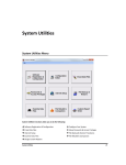
List of Tables
2.1
Built-in gesture recognizers in iOS . . . . . . . . . . . . . . . . 45
3.1
Event callbacks in NetworkController . . . . . . . . . . . . . . 62
B.1 Event callbacks in NetworkController . . . . . . . . . . . . . .
11
ii
12
Listings
2.1
2.2
2.3
2.4
2.5
2.6
3.1
3.2
3.3
3.4
Prolog representation of our radio. . . . . . . . . . . . . . . .
NGOMSL method for turning on a radio . . . . . . . . . . . .
NGOMSL rule represented in prolog . . . . . . . . . . . . . .
Execute engine and locate predicate . . . . . . . . . . . . . . .
The four different touch methods . . . . . . . . . . . . . . . .
Receiving gesture events when a user performs the ”panning”
gesture. . . . . . . . . . . . . . . . . . . . . . . . . . . . . . .
Starting the server with Naga . . . . . . . . . . . . . . . . . .
Structs to hold coordinates of a shape. . . . . . . . . . . . . .
Enum defining six directions in a cartesian coordinate system .
C structures used by OpenGL . . . . . . . . . . . . . . . . . .
13
27
29
29
30
45
46
54
57
58
65
14
CHAPTER
1
Introduction
This thesis is based upon research carried out in a previous project on the
state of multitouch in the consumer market. This project examined the
current situation of available smart home solutions, with a special emphasis on multitouch and its capabilities. Furthermore, the structure of a few
different commercially available multitouch devices was examined to understand in which degree they gave developers the opportunity to interact with
the hardware. A few differences was found across different manufacturers
and platforms, but none of which remarkably constrained functionality. The
project concluded by suggesting a few ways of using multitouch gestures to
resemble gestures performed on real life objects to perform tasks. This thesis
will take this even further, suggesting an application which uses these gestures to ease interaction with virtual objects. More specific, it explores the
idea of creating an intelligent user manual for an object to ease the learning experience of new technologies and technical devices. This chapter will
describe the ultimate project goal, and the motivation that lies behind it.
1.1
Project Context
This report documents the master thesis of the author at at the Norwegian
University of Science and Technology. It is part of the Intelligent Systems
program at the Department of Computer and Information Science, under the
Faculty of Information Technology, Mathematics and Electrical Engineering.
It is partially based on the depth project ”Multitouch Interaction in Smart
15
Homes” conducted by the same author
1.2
Motivation
This section will describe the motivation behind this project. The first section
briefly describes some problems with the situation we have today, while the
second section provides some insight on the personal motivation behind this
project.
1.2.1
Problems Regarding the Current Situation
In the book ”The Age of Spiritual Machines” [Kur99] the author, Ray Kurzweil,
writes about the future course of humanity in relation to technological improvements. In this book he proposes what he calls ”The law of accelerating
returns”, suggesting that the rate of technological development and progress
is constantly accelerating. If we skim through the history of technology during the last 100 years, it is not hard to see a progress in the number of
complex technological devices used in everyday life. Although these devices
most certainly exists to assist us with everyday tasks and automate processes,
it also forces us to understand and operate an increasing amount of nontrivial machines. If these machines were easy to understand and operate, there
would be no problem, but as different manufacturers have different views on
usability, this is often not the reality. As a solution to this, the manufacturers
include large manuals to instruct the user on what to do. The problems here
are numerous:
• For every product sold, a printed manual is often included. The paper industry has for a long time been criticized for its impact on the
environment through harvesting of trees, pollution, and finally large
amounts of waste from used paper.
• Reading manuals will take an increasing amount of time as the number of technological devices increase. This is somewhat limitable by
increasing user friendliness, but no matter how much care one takes
in designing with the user in mind one can’t get around the fact that
users have different backgrounds for understanding how things work.
16
• Manuals mostly needs to be kept as long as the device is in use, taking
up space.
• Reading may not be the most effective way of acquiring practical skills
in something.
Although the user manual in form of printed material most certainly has done
its duty so far, it may be time to rethink the whole concept of user manuals
to come up with a more suitable system for the more modern devices.
Another important topic is the idea of dematerialization. Dematerialization
is the act of gradually exchanging physical objects with virtual ones. The
transfer from physical CDs to virtual music files such as MP3s is an example
of dematerialization. It is an ongoing process to reduce the impacts on the
environment through pollution and destruction
1.2.2
Personal Motivation
In a project preceding this thesis, I investigated the current situation of smart
homes, both as commercially available products and as a field of research.
Even though smart homes, at least the way most people think about them,
still may be a long way from becoming a reality, concepts and ideas from such
homes and solutions are starting to become a reality. The report concluded
by ’nominating’ touch displays as one of the more promising technologies as
of now, with mobile phones, tablets, and laptops among others adopting them
as the primary way of interaction. This new way of interaction has shown a
shift in how devices are operated and in which situations they are used. As
touch displays and interfaces are constantly becoming more popular, I really
wish to see them being utilized in a way that may enhance our everyday
life and experience with new devices. If this can be a part of the global
dematerialization as well, I believe that this really is something to investigate.
Another aspect of my personal motivation is increasing my general understanding of programming, both in the mobile world and in the more traditional world of desktop computers. I wish to investigate possible differences
and, in the case of any, how this affects the way of thinking when developing
for the two platforms. This project will touch a number of programming
topics, ranging from the more trivial to the more advanced subjects, such as
network and 3D programming.
17
1.3
Project Goal
The main goal of this project is to come up with a prototype for an application
that can aid in helping people understand and learn in a more efficient way by
utilizing an increasingly popular technology: touch screens. More specifically,
I wish to develop a tool that eventually may take over the role a user manual
has today, while at the same time improving it. There are a number of ways
to improve what we have today:
• By taking advantage of natural language and artificial intelligence, a
user can ask for what he needs to know instead of looking through table
of contents, finding the correct page, and reading how to accomplish
the task.
• User manuals can be large, and is generally not possible to carry around
at all times. Just like we can carry around our whole music library on
an MP3 player, we could carry around our user manuals on our mobile
phones.
• By giving the user an opportunity to operate directly on a virtual
representation of the device itself, the user can actually perform the
task instead of just reading how to do it.
1.3.1
Hypothesis
H1: Through using a conceptual model close to how the human mind
perceive objects, we can increase consistency both in the creation of new
user manuals and in the learning process.
H2: By taking advantage of multitouch technologies we can introduce a
more natural way of interacting on virtual representations of real-life
objects.
Let us elaborate on these two hypotheses.
A conceptual model is our mental representation of something, describing its
entities and relations between them. This conceptual model describes the
different aspects of the object and is our way of explaining how it works on
an abstract level. When we learn about a new device, we build ourselves such
18
a model, step by step as we understand and learn more. H1 proposes the
idea of using such a conceptual model to support in the process of learning
to operate new devices. By using a conceptual model that fits with the way
our mind perceives and understands devices, and building the application
around this concept, we should be able to increase consistency and the overall
learning process.
A product can be described by its physical attributes and the tasks we can
use it for. In order to make such an application, we can use a system that
integrates both modeling of the product and description of possible actions in
an integrated manner. We can use well established concepts such as GOMS
to describe different actions performable on the device, and reference directly
to the different parts of the model we are creating, thereby ensuring a consistency between the two domains. This opens the way for quite interesting
ways of creating an object and describing its actions: we can give the creator
a lot of freedom, while at the same time ensuring that the finished product
is consistent and gives the user a good learning experience.
H2 proposes some interesting possibilities a mobile phone with a touch display will give us. By displaying a virtual representation of a device on a
multitouch display, and letting the user interact with this model, we can
provide an advanced task-oriented way of helping the user. We can make
use of the fact that touch displays gives us a very direct and natural way of
interacting, and take advantage of concepts such as gestures to implement
a very natural way of operating on what is displayed. We can mimic a lot
of the gestures used in everyday life to turn knobs, press buttons, and thus
bring the interaction very close to real-life operations.
Using gestures to operate the virtual product introduces a level of realism to
the system. Gestures can be made generic in the same way that pushing a
button is a generic action independent of what the button looks like. When
creators develop a new model and its actions, they will not need to worry
about how the user will interact. They can specify the task with the model
and involved components in mind, and the mobile application will then translate actions such as push and turn to corresponding multitouch gestures. At
the same time, we can also ensure that a component is not given an illegal
action. A button on a physical device is usually pushed, not turned, and we
can thus ensure that such logical flaws are taken care of.
19
An interesting side-effect of such a product is the act of ”learning by doing”:
instead of just reading about a topic, one engages in the activity of doing it.
Although driving requires a certain amount of theoretic background, you can
never become a good driver by just memorizing the theory. This translates
to understanding a new device as well: one cannot expect to fully understand
it by just reading about the functionality. By giving the user a virtual model
and a smart, context sensitive helping system, he or she can test functionality
in a failsafe environment.
20
CHAPTER
2
Research
This chapter will start off by investigating related work, before providing
some background theory and use cases to increase understanding of what
the final product will do. It will then follow up with some more in-depth
research on the key aspects of the project to justify a suitable architecture.
2.1
Related Work
[Cha82] describes a few problems of creating user manuals in a way that
best suits the user. Users are different, and especially products that target
more than one user group will meet challenges in creating user manuals
due to the difference in knowledge and method of use across the groups.
Too large of poorly written documentation is hard to read and may create
frustration when the user struggles to perform even simple tasks. This makes
development of user manuals a difficult task: it is absolutely crucial that end
users can turn to the documentation when they struggle with their product.
This is complicated even more with complex devices, as they both increase
the need for user manuals and increase the importance of consistency and
understanding.
[NL05] details two approaches to ensure consistency in user manuals through
co-generation of text and graphics. It demonstrates how these two approaches
can force a consistency between an image and accompanying text, but also
how this text is depending on the user thinking in a specific way to understand the situation. Because two persons may act and think differently, they
21
would ideally need two different user manuals. As an example, consider the
simple situation where you have two equally sized boxes, box A and box B,
placed side by side in a three dimensional environment. While one person
might explain this scene as ”Box A is placed to the left of box B”, the same
scene might be described by someone else as ”Box B is placed to the right
of box A”. Although semantically the same, syntactically they are different.
When describing a more complex scene, you will end up with even more
variations, creating room for misunderstandings and misinterpretations.
[WAF+ 93] documents another approach to creating consistency between graphics and text. It discusses how the usage of multi modality and an iterative
plan-based approach can provide different ways of explaining a scenario to
the user. Consistency is ensured through extracting information about the
components referred to in text, and placing labels showing the user where
the components are located. This introduces problems: if the text refers to
components not visible from a single orientation, we will need several images,
thus forcing the user to mentally unite the two images to understand where
the two components are located in relation to each other.
As we can see, much of the problems with textual user manuals is describing
scenarios and techniques in a consistent manner that is understandable for
everyone reading the manual. This is somewhat improved with the introduction of graphics along with text, but this again introduces new problems
with ensuring consistency between the textual representation and the graphical representation, and how these best can be related to each other. Our
system will not have this problem, as textual explanations is traded with an
interactive model. A sequence of steps is modeled as a series of manipulations
on a model, and thus this system will be more closely related to learning from
an actual person. This may be compared to how pilots practice flying in the
safe environment of a simulator, but employed to more simple and everyday
devices targeted at regular users.
2.2
Theory
This section will first describe how we can translate the physical device into
a virtual representation, represented by a conceptual model. It will then
discuss how this conceptual model will be represented on a more concrete
22
level in our system.
A physical device can be described by its physical attributes and the actions
we can perform with it or use it for. A radio may for example consist of four
visible parts: the actual casing, the power button, the volume dial and the
frequency dial. This same radio will have four different actions to perform as
well: turn the power on, turn the power off, adjust the volume and adjust the
frequency. Describing the physical attributes is achieved through what we
call 3D modeling, and is achieved by using coordinates in three dimensions
to replicate parts of the physical device. This is a science in itself, powering
large industries such as animated movies, games and architectural software.
Describing actions, on the other hand, does not have such a clear candidate.
[CNM83] explains a system called GOMS1 , which is a human information
processor model for describing the interaction between human and computers. We can use this model to create a more defined way of describing steps
needed to fulfill a task. This will be described further in Section 2.2.3, but
first follows a more broad discussion of our representation.
Figure 2.1: Mental models exists both in the minds of designers and users.
To integrate 3D modeling and GOMS modeling, we need a representation
that can be shared between these two domains. Our system should be backed
by an abstract, conceptual model describing the device and its actions. It
1
GOMS: Goals, Operators, Methods, Selection rules
23
needs to be close to how an end user would create his mental model of the
device. Figure 2.1 shows that both designers and users have a mental model
of the same object. By trying to bring these two together, we can increase
consistency and ease the learning process, as users and designers will more
likely see the device in more or less the same manner. Our conceptual model
can be visualized as a tree with the topmost node being the device itself, on
a abstract level, and the children being either parts of the device or possible
actions. When a node representing a part has a child, we can say that the
child is ”placed on” the component itself on the physical device. We can
also introduce our own class hierarchy to give this conceptual model a way
of classifying different nodes as instances of buttons, knobs, and so on. To
make things more clear, let us take the example of a simple radio. The radio
in Figure 2.2 has three components: the casing (1), a power button to turn
on or off the device (2), and a frequency dial (3) to switch the frequency.
A very simplified tree showing the structure of this radio can be seen in
Figure 2.3. Bear in mind that some concepts, such as the object hierarchy,
is not included in this figure.
An important notice is the separation of actions and geometry. The action
group consist of GOMS methods that can be performed on the device, and
the geometry group consist of the different visible parts the device has. Separating these two groups basically makes them independent of each other,
such that deletion of a part will not remove its action, and adding of an
action does not require a component to add it to. This is a fundamental
point that powers the philosophy behind creation of a user manual in our
system: the developer should be free to describe a product the way he or she
wants, and not be constrained by the application. Just as people understand
situations differently, as discussed in Section 2.1, developers may have different preferences in how they want to develop. This is reflected in our model
with the possibilities of creating actions and geometry independent of one
another. By giving developers free reins, the device should be described in
the best possible way independent of the steps taken to get there, and the result should be the same independent of the approach taken by the developer.
Further, the end result can be checked for errors through traversing the geometry nodes and action nodes, and cross checking them against each other
to rule out inconsistencies in naming, types of action, and other attributes.
24
Figure 2.2: Simple radio consisting of 3 components
2.2.1
Representing the Data
How can this abstract representation be realized as a file format? This is
a critical question, and will affect how we implement the applications later
on. As we can see from our example, the conceptual model basically consist
of a number of facts about the device. These facts can be represented by a
knowledge base. A knowledge base is a special kind of database for managing
knowledge, with functionality for retrieving, adding and managing knowledge
about a subject. The subject, in our case, is the device, and the knowledge,
is the facts about the actions and geometry of the device. To accomplish
this, we will use the logic programming language prolog. In prolog, we can
state a as ’ object (Object1)’, which is the equivalent of saying ”Object1 is
an object”. We can also add and delete facts with the built in predicates2
2
In prolog, functions are called predicates. A predicate ’fac/2 ’ is the collection of all
clauses with the clause head ’fac(Arg1, Arg2)’.
25
Figure 2.3: Radio in Fig 2.2 represented as a tree
’ assert /1’ and ’ retract /1’. This means that if we come up with a general way
of representing a node in our object tree, we can easily add and remove nodes
to our knowledge base by asserting and retracting facts. Let us continue our
example with the radio, and see how we can represent this tree as a knowledge
base. A node is represented by the predicate ’frame/4’, with the following
arguments:
1. name(name): the name of the node.
2. is a (type): the type of a node. This is either ”method” for an action,
or ”cube”, ”sphere”, ”cylinder” and so on for geometry.
3. part of (parentName): the name of the parent node. This is a crucial
part to keep the tree structure.
4. properties ([...]) or steps ([...]) : a list of properties for geometry, or
a list of steps to perform for an action.
26
With this in mind, Listing 2.1 illustrates our radio example as prolog code.
Listing 2.1: Prolog representation of our radio.
%The d e v i c e i t s e l f
frame ( name ( r a d i o ) , i s a ( d e v i c e ) , p a r t o f ( n u l l ) ,
properties ( [ . . . ] ) ) .
%Geometry
frame ( name ( c a s i n g ) , i s a ( cube ) , p a r t o f ( d e v i c e ) ,
properties ( [ . . . ] ) ) .
frame ( name ( f r e q u e n c y d i a l ) , i s a ( c y l i n d e r ) , p a r t o f (
device ) , properties ( [ . . . ] ) ) .
frame ( name ( powerbutton ) , i s a ( cube ) , p a r t o f ( d e v i c e ) ,
properties ( [ . . . ] ) ) .
%A c t i o n s
frame ( name ( turnon ) , i s a ( method ) , p a r t o f ( r a d i o ) , s t e p s
([...]) ).
frame ( name ( t u r n o f f ) , i s a ( method ) , p a r t o f ( r a d i o ) ,
steps ( [ . . . ] ) ) .
frame ( name ( r o t a t e f r e q u e n c y d i a l ) , i s a ( method ) , p a r t o f (
radio ) , steps ( [ . . . ] ) ) .
Although pretty straight forward, one point is in need of explanation. The
frame representing the device itself has the parent node ’null’. This is a
keyword often used in programming languages to represent emptiness, or
”nothing”. As this is the topmost node, it has no parent. To keep the frame
structure consistent, the parent is set as ’null’ instead of being removed.
2.2.2
The Geometry Subtree
Let us take a closer look at the geometry subtree. This part of the tree is
perhaps the most intuitive part, as it is quite easy to visualize in relation to
its representation. The objects in this tree represents the real-life parts of a
27
device. The reason behind this is both syntactical and semantical. Creating
the physical objects instead of specifying vertices and faces, like one usually
does in 3D modeling, is meant to increase the feeling of building the actual
device, part by part. This is inspired by the way classes represent objects in
the world of object-oriented programming. On a more syntactical level, this
makes it possible to split up geometry among the different nodes, such that
each node stores its own virtual attributes.
The last argument in a frame is a list of properties that particular component
has. This list will be variable depending on what kind of object it is. Among
others, this list will contain attributes such as size, color and texture. As
an example, a cube can be defined by a point in space with three vectors
emerging in the three different dimensions. This can be represented in the
properties list as ’properties([origin(X, Y, Z), size(X, Y, Z)], color(blue))’.
2.2.3
The Actions Subtree
The actions subtree will contain our representation of GOMS rules to describe
functionality. To suggest a representation, we need to investigate how these
rules function. Although GOMS itself is a very loosely defined framework,
a variation of GOMS called NGOMSL3 defines a more structured syntax to
GOMS by defining a specific way of writing rules. A rule has a goal, and
consists of a set of operators to achieve this goal. These sets of operators are
called methods. Finally, if there is more than one way of achieving a goal we
can specify selection rules. Listing 2.2 shows how an NGOMSL method for
turning on a radio might be specified.
In addition, a step may contain a subgoal that must be accomplished before
proceeding to the next step. As we can see, these NGOMSL rules provides
a more strict way of using GOMS. Although this framework is meant as a
way of evaluating the complexity of certain tasks on a system, we can see
that it works as a way of describing a certain task in a step-wise manner as
well. This description of a task can further be translated into prolog-facts by
specifying certain grammar rules. Listing 2.3 shows how the NGOMSL rule
in Listing 2.2 can be realized as prolog facts.
3
NGOMSL: Natural GOMS Language
28
Listing 2.2: NGOMSL method for turning on a radio
Method for g o a l : t urn on r a d i o .
Step 1 : l o c a t e t he placement o f th e power
button .
Step 2 : p o s i t i o n d e v i c e with power button
visible .
Step 3 : move hand t o power button .
Step 4 : p r e s s power button .
Step 5 : return with g o a l a c c o m p l i s h e d
Listing 2.3: NGOMSL rule represented in prolog
%Frame r e p r e s e n t i n g power button
frame ( name ( powerbutton ) , i s a ( cube ) , p a r t o f ( d e v i c e ) ,
properties ( [ . . . ] ) ) .
%Frame r e p r e s e n t i n g NGOMSL r u l e
frame ( name ( ’ turn on r a d i o ’ ) , i s a ( g o a l ) , p a r t o f ( d e v i c e
) , s t e p s ( [ l o c a t e ( powerbutton ) , m a k e v i s i b l e (
powerbutton ) , move hand ( powerbutton ) , p us h b ut t o n (
powerbutton ) , return ( ) ] ) ) .
As can be seen, each of the steps is modeled as a generic function with the
involved part as a parameter. These steps can be executed with a predicate
that iterates over a list of steps, and executes each step. As an example,
Listing 2.4 shows how such an execute engine can be implemented along
with a simple and generic ’locate’ step.
29
Listing 2.4: Execute engine and locate predicate
%Execute e n g i n e
execute ( [ ] ) .
e x e c u t e ( [ Step | S t e p s ] ) :−
Step ,
execute ( Steps ) .
%G e n e r i c l o c a t e s t e p
l o c a t e ( Part ) :−
c h e c k e x i s t s ( Part ) ,
i s o f k i n d ( Part , ’ Object ’ ) ,
r e t r i e v p o s i t i o n ( Part ) .
When this predicate is called with the argument ’powerbutton’, the ’Part’
variable will be bound to ’powerbutton’. First, a frame with the name ’powerbutton’ is checked for existence. Second, we check to see if ’powerbutton’ is
a part of our object hierarchy to rid out the possibility of referring to frames
not representing geometry. Finally, the position of ’powerbutton’ is retrieved.
If any of these fails, the execution of the function is stopped and ’false’ will be
returned. Even in this first step, we have enforced a certain consistency between the two domains by only allowing geometry, or subclasses of ’Object’,
to be located.
2.3
Creating the Model
As this chapter has shown, we have come up with our own representation
of 3D data. A problem with this representation is that it is fundamentally
different from how more well known commercial applications represent 3D
data. The way our representation is laid out, we refer to surfaces and larger
structures of a device. A more usual way of storing information is through
highly optimized file structures specially designed for its application. The
difference here is that our representation has the user in focus and tries to
present the data in a format more readable for him or her, while existing
3D-modeling applications mostly has the model and its data in focus. While
30
this may increase performance and give the user more control over visual
aspects, it also introduces a much steeper learning curve.
A 3D model consists of a finite number of points, or vertices, in a three
dimensional space. These vertices are then combined to create what we call
polygons, which in essence is a plane between a number of these points. If we
exclude textures, lighting and so on, these vertices and polygons is enough
information for the 3D application to render the object. Because of this,
file structures for 3D models are often just different ways of storing such
information. To confirm this, we will take a look at how a few common
model formats store information. Sadly, most of the commercial applications
have proprietary, closed formats and do not make their specifications publicly
available. Some of these formats have been reverse engineered, and therefore
been more or less documented. This will however not be considered here,
as it may both be subject to change and cannot be guaranteed as being one
hundred percent correct. The remainder of this section will explain our needs
when creating a model, and then investigate any open, well documented file
formats that may be suitable for our purpose.
When we create a new model, the focus will be on both creating the geometry
and actions. Because actions and geometry relate, we need to be able to
name parts of our object to allow for referencing between the two domains.
An action for turning on a device would perhaps to refer to the front of
the power button. Storing such information is therefore crucial. With the
vast amount of established 3D file formats that exists, compiling a list of
possible candidates is difficult. After a lot of research, it seems that the most
up-to-date list is held by Wikipedia [Wik11c]. Traversing this list proposes
two formats that are designed with interchangeability and openness in mind:
X3D, maintained by the Web3D Consortium, and COLLADA, maintained
by the Khronos Group.
X3D
X3D is the ISO standard file format for 3D content delivery. It is maintained
by the Web3D Consortium, and is meant as a successor for the old VRML
format. Its abstract specification is found in ISO/IEC 19775. Although it is
yet to be accepted by the more notable, proprietary applications, it seems to
have a higher acceptance rate in open source applications. Web3D Consortium describes it as a open standards file format and playback architecture
that provides storage, retrieval and playback of real time graphics content.
31
Its feature set is rich, ranging from describing simple shapes to programmable
shaders, scripting and physics. A more thorough description can be found at
[Con11]. Its format is XML-based, making it very suitable for the web and
rendering in web pages. This also makes parsing and file reading a whole lot
easier due to the wide support of XML in a number of popular programming
languages. X3D’s format description is extensive and too complex to even
attempt to explain in any detail here. The more interesting geometry-part is
usually built up in the following manner: surrounding all geometry is a Scene
-node, which in turn contains one or more Shape-nodes to store information
about a shape. This node has sub-nodes describing its appearance:
• Color, texture and other visual aspects is specified in an Appearancenode.
• Geometry is specified in a node where the tag refers to the type of
object: for example Box, Sphere or IndexedFaceSet.
Shape-nodes can also be grouped.
COLLADA
COLLADA is a file format intended as a intermediate storage between two
or more applications for creation or display of graphical content. It was originally created by Sony, but is now maintained by the Khronos Group, who
also is behind the popular OpenGL standard. Its main purpose is to function as a intermediate format in a pipeline consisting of two or more content
creation applications. It is widely supported by popular 3D-modeling applications as a secondary format, and even supported as a loadable format
by some game engines [Wik11a]. COLLADA is also a XML-based format,
and therefore has a lot of the same pros and cons as X3D has in terms of
parsing. Because COLLADA is meant as a intermediate format supporting
most of the different subjects in 3D modeling, it also has a quite complex and
extensive format description. The overall structure is split into different ”libraries”. library materials and library effects defines the visual aspects of
a shape, while library geometries defines the geometry. library −geometries
then contains one or more geometry-nodes. Each geometry-node then has
elements with arrays of floats defining the shape.
X3D and COLLADA has two very different approaches to describing graphical content: while COLLADA tries to be more of a connecting format to
describe a scene, X3D can describe the whole rendering pipeline and mainly
32
targets web-based applications such as web browsers. This also shows in
how the two formats have been accepted and adopted by the market. COLLADA is highly supported by popular digital content creation applications,
but applications that just load and display models usually has other preferred
formats. X3D seems to be more or less purely represented in relation with
the web. For our use, none of these two formats will be very suitable. X3D
is way to complex and targets the wrong market. Trying to adapt a format
for a situation it is not meant to be used in will almost certainly result in
more or less significant problems. COLLADA is also very complex for what
we need, and is a bit to technical and abstract for it to suit our purpose.
This lack of existing file formats to use gives us a few problems. Although
a few commercial 3D modeling applications support the addition of custom
export engines, writing such exporters can be very time-consuming. In addition, using an exporter will only update the geometry part of our file upon
save, and this has quite an impact on our idea of being able to alternate
between the two domains of actions and geometry. As a result of this, the
only ideal solution is to implement an integrated application for modeling
both geometry and GOMS rules. This presents us with quite a dilemma:
the creation of such an application will severely limit the functionality of the
mobile application, but at the same time there is no point in implementing the mobile application without being able to develop models for it. We
will therefore shift our focus towards creating these two applications with a
minimum of functionality to prove the utility of such a system.
2.4
2.4.1
Platforms
The Mobile Application
Although an application such as this ideally should exist on every mobile
platform available, we need to settle for one to create a prototype for first.
During the project leading to this thesis [Sol10], the current situation of
multitouch-enabled smart phones was examined. If we take both the multitouch smartphone market and the tablet market into account, there are three
major operating systems to consider: Android, iOS and Windows Phone 7,
with the last-mentioned only being represented on the mobile platform as
33
of this moment. Android and iOS are both very popular, and would have
been good candidates for such a prototype. Android does, however, have a
few problems with multitouch and fragmentation. Different Android-based
phones use different touch screens, and some of them suffer from poor quality touch recognition [Wim11]. Some of these problems can be partly or
fully eliminated through extensive testing and conditional coding, but this
is out of the scope of such a short-time project. Due to this, and personal
experience with both Android and iOS programming, iOS will be the chosen
platform for the mobile part of this project. The rest of this thesis will assume this, but solutions having clear advantages in the form of cross platform
development will be given higher priority than others.
2.4.2
The Server
In addition to the mobile application, we will need a server to act as a library
of manuals. This server will, upon request, present the mobile application
with a list of all available user manuals. As mentioned in Section 2.2.1,
a prolog knowledge base will serve as the final format of a user manual.
This will work in the following manner: different user manuals are stored in
their own files. When a user requests to load a user manual, the server will
open a prolog instance for that specific user and load the contents of the file
corresponding to the user manual into this instance. The mobile application
can then query the server to retrieve geometry and actions, and present it
to the user. The server therefore needs to reside on a platform with an
existing implementation of prolog. As with file formats, the most up-to-date
list of prolog implementations found reside on Wikipedia [Wik11b]. One of
the more commonly used implementations is SWI-Prolog. It has been under
continuous development since 1987, and it exists natively for Unix, Windows
and Mac OS. It also has both a C and Java interface, making a cross platform
solution a viable choice. By writing our server in Java, and using SWI-Prolog
as our prolog runtime, it should be possible to run the server on both Unix,
Windows and Mac OS machines.
34
2.4.3
The Creator Application
As discovered in Section 2.3, we will need to implement our own application for creating models. Due to personal experience and to increase the
possibility of code reuse, Mac OS is chosen as the platform for the creation
application. This may sound as a contradiction to the statement of promoting cross platform solutions in Section 2.4.2, but it should be noted that this
is largely due to the ability of reusing code and classes. Developing for iOS
and Mac OS is largely the same, and as both of these applications revolve
around 3D graphics, it makes sense to choose the same language.
2.5
Networking
Networking, although not the biggest part of this system, is an important
topic to research before implementation. This system relies on a constant
connection between the mobile application and the server to function correctly. Thinking through a few scenarios is therefore of high importance. Although the mobile application relies on a constant connection to the server,
this should be transparent to the end user. When we consider network technologies, there are in essence two issues to consider: speed and quality. In an
ideal world there would be no delay and the quality would be perfect, but in
reality we often have to choose between one of the two. Although speed most
certainly is important to increase usability in this case, quality is definitely
even more important. Ensuring that no packet loss occurs is crucial if we
want to guarantee a correct and consistent user experience. The Transmission Control Protocol (TCP) offers such stability and reliability between two
nodes, and will therefore be used as transport protocol in this system.
As our platforms of choice requires us to code both in Java and Objective-C,
we are in need of networking solutions for both of these languages. Following
is an investigation of what our possibilities are in each of these languages.
35
2.5.1
Java
The Java runtime comes bundled with a huge number of built-in libraries,
making complex tasks such as networking a lot easier. TCP networking can
be realized through the java .net.Socket and java .net.ServerSocket classes,
along with different reader- and writer-classes for reading and writing information to and from the sockets. Java takes care of all of the low-level socket
handling for us, all we need to do is connect, and we can send and receive
data.
However, these built-in libraries use what we call synchronous I/O, and will
only work for one concurrent user unless we implement threading. Threading
gives us the ability to have several concurrent users, but also requires us to
have two threads per user and one thread for the accepting socket. This can
potentially spawn a great number of threads and therefore be a stress-factor
for the server. As an opposing technology to synchronous I/O, we have
asynchronous I/O. Proper, asynchronous I/O, does not rely on threading
sockets, and will therefore be easier on the server and probably easier to
implement. Java offers asynchronous I/O through the java.NIO package, but
setting this up in a application is far from trivial. Luckily, there exists a few
libraries which eases the work quite a bit:
• Grizzly is a large-scale wrapper around the java.NIO libraries to make
it easier to get up and running with asynchronous calls. It is used in
Sun’s Glassfish server, which means it should be a quite stable framework.
http://grizzly.java.net/
• Naga is a very small library providing asynchronous I/O. It is intended
for smaller projects, and comes self contained in a jar-file without any
external dependencies.
http://code.google.com/p/naga/
Given that Grizzly is a much larger product than Naga, it also requires more
work to set up. The overhead for smaller project will therefore be larger
than when using smaller libraries like Naga. Nevertheless, care should be
taken when integrating any of these in our project. By choosing a strict
architecture for the server, we can easily exchange the networking library
later on with a new one without affecting the rest of our program. This will
36
allow us to choose a more lightweight framework for testing and prototyping,
but also arrange for more complex and large-scale frameworks to be used
later on.
2.5.2
Objective-C
Objective-C is by nature a more low-level language than Java, and although
Apple strives to offer relatively easy-to-use libraries for common programming tasks, networking is one of the more complex things one can attempt
at. On iOS, the only provided functionality is through the CFNetwork library. CFNetwork provides access to very low-level functions using BSD
sockets for networking. Implementing a full networking service for an application through BSD sockets is a tedious task, and requires among others
reading raw bit streams. Making sure it is stable as well, is even harder and
requires a fair amount of error checking. Without any extensive knowledge
on sockets and lower-level networking, using BSD sockets is a difficult task.
The amount of third-party frameworks for Objective-C is a lot smaller than
for Java. The iOS platform has only been around since 2007 with the release
of the first iPhone, and has therefore not managed to become quite as popular as the more widely-used Java platform. There does, however, exist a
library called CocoaAsyncSocket [Deu10] which provides asynchronous networking over both TCP and UDP. CocoaAsyncSocket uses a runloop-based
approach instead of threading, and supports the popular delegate pattern.
By implementing this library, we therefore only have to code how we want
our application to react on errors, connections, read completions and write
completions, and not the network logic itself.
2.5.3
Zero Configuration Networking
A subject that is not crucial to implement in a prototype, but most certainly
convenient, is zero configuration networking, or zeroconf. Zeroconf is a set of
techniques to enable networking without any configuration. When a server
and a client is on the same network, zeroconf technology can for example be
used by the client to automatically connect to the server without specifying
an IP and a port. This is practical in networks with dynamic IP addresses,
37
where the addresses may change after a given amount of time. Implementing
zeroconf may also speed up testing and troubleshooting by a certain factor
as it removes the need for specifying the IP and port to the server upon
connection.
If we want to take advantage of zeroconf in this system, we need to broadcast
a service from the server and search for the same service in our mobile application. This means that we need an implementation that both has interfaces
for Java and Objective-C, C or C++. Apples own implementation, Bonjour
[Inc11a], does this. It is natively supported on all iOS devices and Macs, and
Apple provides bindings for Java.
2.6
Displaying and Operating on the Model
A rather large subject of this project is how we display the model for a user,
and how he or she would operate on it. Rendering 3D graphics on computer
displays is rather complex both theoretically and practically, and interaction
demands some thought to make it as user friendly as possible. This section
will first discuss rendering, and then present a few thoughts on how we will
let the user interact with our application.
2.6.1
Rendering 3D Objects
Rendering of 3D scenes and objects on computer displays is a subject of
constant research and development. Much of this is due to the video game
industry pushing the limits to create more and more realistic games. Creating
a large-scale rendering engine capable of producing graphics close to real life
has become a science in itself, with some companies subsisting on just this.
This has carried over to the mobile platforms, with large companies providing
full-featured engines for entry-level prices.
When programming 3D applications, one often uses an API available for the
specific platform one is developing for. DirectX and OpenGL is two of the
more popular APIs, and have existed since 1995 and 1992, respectively. They
both have their own mobile version as well: Direct3D Mobile and OpenGL
ES. The iOS operating provides programmers with an implementation of
38
OpenGL ES, which seems to be the dominating API on the mobile platform.
Currently, Windows Phone 7 is the only one providing support for Direct3D
Mobile. OpenGL ES is therefore a necessary choice for rendering our model.
There is generally two different approaches we can take when implementing
a rendering engine: creating the engine from scratch without any third party
solutions, or using a framework built with the purpose of rendering 3D models
in mind. The first approach is often a lot more complex than the second, as
it requires some knowledge of how rendering works on a deeper level. Let us
therefore examine some of the existing frameworks first:
• Unreal Development Kit is an implementation of the popular Unreal Engine for desktop computers on iOS. UDK exists only for Windows, and will build a complete iOS app for you. This development kit
has been used to built triple A titles such as Gears of War and Infinity
Blade. You do not have the ability to alter any of the code produced
by UDK. This really renders the development kit useless in our case, as
we need the engine to communicate with other parts of the application.
http://www.udk.com/
• Airplay SDK is more of a cross platform SDK that allows you to write
the same code for multiple platforms. Such SDKs have become more
popular now that there are several actors having a considerable market
share. According to their website, the SDK has been used in a number
of popular game titles. If an application made with Airplay SDK is to
be distributed to other platforms than iOS, a license is needed.
http://www.airplaysdk.com/
• Unity 3 is a development kit purely targeted against game development. It also focuses on cross platform development with the ability
to distribute the same code to a number of different platforms. Unity
uses a addon based license program, where one can buy the right to
distribute for different platforms.
http://unity3d.com/
• Bork3D is a smaller game engine targeted for the iOS platform. This
is not a full featured development kit like the other alternatives, but
a compact game engine ready for integration with iOS projects. To
obtain Bork3D one needs to purchase a license.
http://www.bork3d.com/
39
Although using a existing framework or game engine probably will save some
time on larger projects, the benefits are smaller on smaller projects. Understanding and learning the frameworks can take an extensive amount of time
as some of them are quite large and complex. The license fees can also be a
problem, as smaller teams have quite restricted resources compared to larger
companies. As this project intends to only use open source solutions, licensed
solutions are out of the scope.
There exists a few other smaller, open source frameworks as well, but they are
all in early development or suffers from poor documentation. Based on this,
the best option seems to be to implement a rendering engine from scratch.
Although this is considered a time-consuming task, there are a few shortcuts
one can take in a prototype. There are also a few advantages in not having to
rely on third party frameworks. First of all, we can tailor our rendering engine
as we want it for perfect integration with the rest of our application, instead
of tailoring our own application to fit with the framework. Second, you get
complete control over the whole code base. This can make bug tracking
easier as you have greater control of the whole pipeline. Third, we can
choose an architecture that makes porting to other platforms later on easier.
Although the prototype only has intentions of running on the iOS platform,
it is good practice to advocate solutions that are more easily ported to new
platforms. The book iPhone 3D Programming [Rid10] is an introduction to
3D programming on the iOS platform with such an approach. It offers stepby-step instructions taking you from very easy examples to more advanced
ones. It also takes you through the fundamentals of graphics programming
such as matrices and quaternions. A benefit of using this book as inspiration
in the development of a rendering engine is the cross platform approach.
Although the book targets iOS, all of the rendering code is written in pure
C++ and can therefore easily be ported to other platforms as well.
2.6.2
Interaction with the Model
There are mainly two aspects of interaction with the model: the user aspect,
dealing with how users will act on the model and how we best can promote
understanding, and the technical aspect, dealing with how we can translate
the users actions into meaningful interaction with a virtual model. Both are
equally important. If the first aspect is not well thought through, we will end
40
up with an application that feels unnatural and may have a steep learning
curve, which is the exact opposite of what we want. If we are lacking on
the second aspect, the end product may feel unfinished and we may have
problems creating gestures for the operations we want.
The User Aspect
The computer mouse has been the preferred mean of interaction as long as
the personal computer has existed. On a standstill computer it makes sense
to use a separate device as input instead of operating directly on the display,
as they are more often than not vertical devices. Separate devices translate
poorly to mobile devices and contradicts the thought of them as being independent, small devices. Because of this, alternative ways of interacting has
been needed. For a long time directional pads was used to control either
grid-based layouts or as a direct substitute for the original computer mouse.
In 2007, the first capacitive touch screen cellphone, LG Prada KE850, was released, and disrupted the market completely. Although touch screen phones
had existed for quite some time, these had mostly been operated with a stylus, as they used resistive touch screens. The capacitive screen allowed for
direct input with a finger, which removed the need for a stylus completely.
After a while Apple released a similar device, the iPhone, and Android based
phones followed closely short after that. These new phones created a disruption in how we operated our phones. Graphical interface elements became
larger as a reaction to the size of a finger compared to a stylus or mouse
pointer, and gestural interfaces saw the daylight in commercial products.
Although greatly accepted by the masses, opponents of gestural interfaces
have argued that it breaks with established norms and conventions of interaction. Don Norman, one of the founders of the Nielsen Norman group,
has criticized them for, among others, lacking discoverability and not having
any settled standards [NN11]. He proposes that for gestures to be natural
and take over for other forms of input, they need to have a more defined
ruleset and have more consistent meanings in the user interface. As of now,
there is no guarantee that a swipe gesture in one application executes the
same action that it does in another. This leads to confusion, and eventually
frustration.
[DM11] elaborates on a study conducted in 9 different countries on the cul41
tural differences and similarities with regards to gestures. It concludes that
regardless of clear cultural differences, people mostly use similar or the same
gestures for the same tasks. The only difference of any significance was the
more widespread use of symbolic, or offline4 , gestures by the chinese participants. This suggests the need for more research on this particular area,
but little seems to have been done. Instead, by looking at mobile applications with a similar interaction pattern as our application, we can draw a
few conclusions on what seems to be most widely used. One such application
is Molecules by Sunset Lake Software, shown in Figure 2.4. This application displays a 3D rendering of molecules directly on the screen, and allows
you to manipulate the molecules through gestures. By dragging one finger
across the screen, you rotate the molecules corresponding to the direction.
To zoom in or out, you move two fingers further away from each other or
closer to each other. This gesture is called pinch, and is deployed other places
in iOS as well. Last, you can pan the molecules by moving two fingers across
the screen, moving the molecules in the corresponding direction. Although
these gestures are completely hidden with no clue as to how they work, discovering them is remarkably easy. To understand some of the choices made
during the development of Molecules, Brad Larson, the developer of the application was contacted. The full conversation can be found in Appendix A.
He released Molecules at the same time the App Store opened, at a time
when gestural interfaces was still at a very early stage in commercial devices.
His choices was therefore heavily inspired by gestures used elsewhere in iOS.
Safari, the built in web browser, uses one finger dragging to scroll the webpage and pinching to zoom in and out. Note the difference here: while safari
uses one finger to move something around, Molecules uses two. There is,
however, a quite natural reason for this: while the main action in Safari is
scrolling a webpage, the main activity in Molecules is rotating the model to
see different sides of it. There is also the fact that Safari displays 2D content,
and Molecules displays 3D content. Safari also has the pinch gesture, which
translates to zooming in and out on the webpage. Other built-in iOS applications using similar gestures are ’Maps’ and ’Photos’. We therefore need
to define what the main activity in our app is to be able to make rational
choices for the gestures. When a user is presented with a device in the app,
a natural response would be to examine the different aspects of it, thereby
4
Offline gestures: a gesture processed after the user interaction with the object.
Online gesture: a gesture processed while the user is interacting with the object.
42
needing to rotate it. As the different aspects of a device might be too small
to see from the predefined position, giving him or her the ability to zoom in
or out is valuable. Zooming alone does not provide any meaningful value if
you only have the possibility to zoom in on one point. This is fixed by allowing users to move the object around as well. Moving a object is a ’heavier’
operation than rotating it around a given point, and is therefore achieved by
using two fingers instead of one. Together, these three gestures provides you
with the ability to see any part of a device in the desired scale.
Figure 2.4: The iPhone application Molecules, by Sunset Lake Software.
The already discussed gestures is enough when all we want to do is see all
the different parts of a device. In addition to this, we also need support
for gestures that interact with devices on a deeper level, such as pressing
buttons, turning knobs and flipping switches. This is a subject that would
need professional user testing on a commercial level, but for this prototype
we will let us inspire by how such actions are carried out in the real world.
43
When you press a button, you often just use one finger and press the button
lightly until it moves inward. This can be realized by a simple tap on the
virtual button to start an animation showing the button going inwards and
coming out again. Similarly, flipping a switch can be realized by pressing
the screen, and moving the switch in the correct direction. This can even be
animated in real time to provide instant satisfaction for the user. A more
advanced gesture is that of turning a knob. A physical knob often requires
you to put at least one finger on each side of the knob and turn your hand.
This is impossible on a 2D display, as it also requires physical depth. We
can, however, mimic this action by placing two fingers on the flat surface of
the knob, and rotate them around the center. Another way might be to only
use one finger, place it on the edge of the flat surface, and move it in a circle
around the center. Both makes makes sense in the way that they mimic a
real life way gesture, and it might even be appropriate to give the user both
opportunities. As stated, this is an area in need of deeper research and user
testing, and will not be given much attention in the prototype.
The Technical Aspect
How do we realize such gestures in an application? To figure this out, we
need to understand how iOS handles touches in software. When you touch
the display on a iOS device, a UIEvent instance is generated by the operating
system. This event, along with an instance of NSSet containing UITouches, is
then sent to the appropriate responder. iOS does all of the calculations to find
the appropriate responder for you, all you need to do is to be sure to catch it.
Depending on the type of touch event, one of the four different methods seen
in Listing 2.5 will be called. We can therefore easily choose when we want
to react to a touch. A deeper explanation of how the event system works
in iOS can be found in the documentation [Inc11b]. In addition to these
four methods, iOS provides support for some built-in gesture recognizers,
shown in Table 2.1. A class can set itself as the receiver of such gestures
with the code shown in Listing 2.6, or the equivalent for other gestures than
panning. Gestures can be either discrete or continuous, depending on how
they are meant to work. As Figure 2.5 shows, a discrete gesture only has one
callback to the receiver, while a continuous gesture sends a gesture event to
the receiver until the gesture is either finished or cancelled.
44
Table 2.1: Built-in gesture recognizers in iOS
Gesture
UIKit class
Tapping
UITapGestureRecognizer
Pinching in and out
UIPinchGestureRecognizer
Rotating
UIRotationGestureRecognizer
Swiping
UISwipeGestureRecognizer
Panning
UIPanGestureRecognizer
Long press (or tap and hold) UILongPressGestureRecognizer
Listing 2.5: The four different touch methods
− ( void ) touchesBegan : ( NSSet ∗) t o u c h e s withEvent : (
UIEvent ∗) e v e n t ;
− ( void ) touchesMoved : ( NSSet ∗) t o u c h e s withEvent : (
UIEvent ∗) e v e n t ;
− ( void ) touchesEnded : ( NSSet ∗) t o u c h e s withEvent : (
UIEvent ∗) e v e n t ;
− ( void ) t o u c h e s C a n c e l l e d : ( NSSet ∗) t o u c h e s withEvent : (
UIEvent ∗) e v e n t ;
45
Listing 2.6: Receiving gesture events when a user performs the ”panning”
gesture.
// Create pan g e s t u r e
− ( void ) c r e a t e P a n G e s t u r e R e c o g n i z e {
UIPanGestureRecognizer ∗ p a n R e c o g n i z e r = [ [
UIPanGestureRecognizer a l l o c ] i n i t W i t h T a r g e t
: s e l f a c t i o n : @ s e l e c t o r ( handlePanGesture : ) ] ;
[ s e l f . view a d d G e s t u r e R e c o g n i z e r : p a n R e c o g n i z e r ] ;
[ panRecognizer r e l e a s e ] ;
}
// Catch pan g e s t u r e
− ( IBAction ) handlePanGesture : ( UIPanGestureRecognizer ∗)
panGesture {
// Get t o u c h p o i n t and r e a c t a c c o r d i n g l y
}
Figure 2.5: Discrete versus continuous gestures. Image courtesy of Apple
46
In addition to this, iOS also supports the creation of custom gesture recognizers through subclassing UIGestureRecognizer, and implementing the four
methods found in Listing 2.5. In these methods, you set the state of the
gesture to indicate if it is a valid gesture of not. A more detailed description
of how one can implement custom gestures can be read in the iOS documentation [Inc11b].
As have been shown, iOS has very good support for gestural interfaces. The
operating system provides three different ways of using touches: through the
four methods in Listing 2.5, by using the built-in gesture recognizers, and
by implementing custom gesture recognizers. The first way works best in
situations where you just want quick access to touches sent to a specific view.
The second way is convenient when you want to add well-known gestures to
our application. The real benefit of using these is the consistency in gestures
across the whole OS. These gestures will work exactly the same way they work
in the apps provided by Apple. The last way provides you with functionality
for creating your own, more complex, gestures, in a consistent manner. In
our application, this could for example be used to create custom gestures for
more advanced device controls.
The next step is manipulating the 3D scene based on touch input. As we have
seen, we have several possible ways of implementing the different gestures.
No matter how we do this, the results will need to be sent to the rendering
engine for consideration. There are basically 2 operations we need to take
care of for either the whole device or parts of it: translation and rotation.
Translating an object in space means moving every point of the object an
equal distance in a given direction. If we assume a cartesian coordinate
system with positive Z values pointing out of the screen, which is standard
in OpenGL, we can achieve panning by translating along the X and Y axis
and zooming by translating along the Z axis. Two-finger movement should
therefore manipulate the X and Y values, while pinching will manipulate the
Z value. Rotation is a bit more difficult to achieve due to a phenomena called
gimbal lock. In short, a gimbal lock can occur when you try to rotate an
object in three dimensions, and will effectively make you lose one degree of
freedom. A common way to solve this problem is by introducing quaternions
[Han07]. Coupled with an arcball-like5 rotation system, as seen in Figure 2.6,
5
An arcball is a system for translating 2D coordinates from the input device into 3D
coordinates.
47
we overcome the problem of gimbal lock and can rotate an object in 3D space
any way we would like.
Figure 2.6: Translating 2D coordinates into 3D coordinates through the use
of an arcball.
48
CHAPTER
3
Solution & Implementation
Before we discuss the implementation, let us recapitulate on the essence of
Chapter 2 to clarify some choices. Because of the problems with existing
file formats and our needs, we decided to use prolog as a knowledge base of
devices. Although prolog implementations and interfaces for C and C++ exists, making it work with Objective-C proved harder than expected. Having
a stationary server in Java and accepting connections over TCP therefore
seems like a rational choice. This is further reasoned for with the ease of
adding new user manuals such an approach gives us: the mobile application
does not need updating, and becomes more of a ’shell’ application able to
render our format. Because we practically have invented our own format, and
have such specific needs in how we create new user manuals, an application
for creating user manuals will also need to be developed. This was originally
not part of the plan, as it was expected that existing applications could be
used with or without modification, and will therefore have quite some impact
on the functionality in the mobile application. It does, however, give us the
opportunity to create a unique application and implement exactly what we
need for the task. It will most likely lift the overall impression of the system.
To increase the possibilities of code reuse, this creator application will also
be developed in Objective-C. Cross platform-compatibility is less important
on the creator, as this is not something intended to be used by everyone.
To increase understanding and consistency, there are a few architectural
choices and patterns that are followed throughout most of the code. Where
code relies very much on choices made in Chapter 2, or where it is probable
that alternative choices may be advantageous later on, the code has been
49
divided into logical modules to make changes easier to make. An example
of this is in the networking in the mobile application: the network should
be mostly transparent to the application itself, and has therefore been abstracted away by a prolog interface in between, such that instead of doing
network calls you do prolog calls. There is a very important distinction here:
instead of retrieving your information from a server on the network, you retrieve your information from a knowledge base. In addition to this, there are
two very popular patterns that have been used throughout the development:
model-view-controller (MVC) and delegation. MVC is a increasingly popular
pattern parting logic, content and presentation from each other. The idea
is simple: in the bottom, you have models containing information. These
models are managed through controllers. Views can query controllers to
retrieve information from the models, or modify the models by telling the
controller to do so. The real advantage is that the format of the underlying
data is abstracted away from presentation. The Cocoa and Cocoa Touch
API is based on this exact way of thinking, and Objective-C developers are
therefore also encouraged to do so. Delegation is another popular pattern in
Cocoa and Cocoa Touch. Some classes support, and expect, the usage of delegates. By setting your class as a delegate of another class, you are expected
to implement a certain number of methods specified in an Objective-C formal protocol. This is equivalent with interfaces in java, with the exception
that you will not get any error or warning if you do not conform to the protocol. Usage of delegates is also heavily encouraged as it abstracts away the
underlying class, and can in some cases remove the need for subclassing.
3.1
Overall Architecture
The end, imagined, architecture, consists of four different applications: the
creator application and its server, and the mobile application and its server.
Two different servers are required, as they will have some difference in functionality. The creator server will have a lot of extra functionality for manipulating information in the knowledge base, which is not needed in the server
for the mobile application. The creator server will also generally only work
with one file at a time, while the server for the mobile application needs
to be able to load different files for different devices. As this is more of a
prototype, the two servers have been merged, resulting in one server with all
50
of the functionality from the creator server, only having the ability to work
with one device at a time. The creator application and mobile application
therefore connects to the same server, and can also do so at the same time.
This also eases development some, as created devices can be tested on a iOS
device instantly instead of first being transferred to another server.
Figure 3.1: The overall architecture of our system.
The overall architecture will therefore be like in Figure 3.1. As can be seen,
all communication happens through TCP, with the server being the center
point. In this figure, both the server and the creator application is residing on
the same computer. This is not a requirement, but more of a good practice.
If we place them on different computers, the responsiveness of the creator
application will become dependent on the network configuration and speed.
It does however not have any effect on the development, as all communication
will go through TCP.
3.2
The Server
Although quite straightforward compared to the two other applications, the
server is central and very important to the system as a whole. The decision
to develop the server in java has several causes: the two different servers
we ideally would develop would share a lot of the same code, but we should
not restrict the mobile application server to run on a specific OS as this
would severely reduce its usefulness in a home. In addition to this, when
51
we look at what interfaces and bindings the different prolog implementations
offers, java seems to be a quite popular choice. There even exists some prolog
implementations written natively in java. A screenshot of the server with the
creator application just connected can be seen in Figure 3.2
Figure 3.2: Screenshot of the server with the creator application connected.
The server should function as a interactive prolog interpreter understanding
the ISO standard1 . It has been modeled after SWI-prologs interpreter and
aims to function the same way, with one exception: because we send everything over TCP before it is parsed as prolog, we can add commands that
perform certain actions on the server instead of being parsed as prolog. This
can for example be a command for saving the current state of the interpreter
to a file.
Figure 3.3 demonstrates a simplified class diagram of the server. CreatorServer
is the main-class. When the application is started, ’ start ()’ is called, which
first starts the ServiceAnnouncer, and then the socket in AsyncConnection.
ServiceAnnouncer is a class for broadcasting a service on the local network,
so the server can be found without knowing its IP. AsyncConnection holds
all of the network logic. It controls an asynchronous NIOSocket and sets it
1
ISO prolog is a standardization of the many different prolog implementations, defined
in ISO/IEC 13211-1 and ISO/IEC 13211-2.
52
Figure 3.3: Simplified class diagram of the server architecture.
to listen on a specified port upon start. Although networking is a quite complex task, use of the Naga library simplifies it to event-style programming.
A simplified version of AsyncConnections ’ start ()’ is shown in Listing 3.1
53
Listing 3.1: Starting the server with Naga
public void s t a r t ( ) {
s o c k e t . s e t C o n n e c t i o n A c c e p t o r ( ConnectionAcceptor .ALLOW
);
s o c k e t . l i s t e n (new S e r v e r S o c k e t O b s e r v e r A d a p t e r ( ) {
public void newConnection ( NIOSocket n i o S o c k e t ) {
n i o S o c k e t . s e t P a c k e t R e a d e r (new
AsciiLinePacketReader () ) ;
n i o S o c k e t . l i s t e n (new SocketObserverAdapter ( ) {
public void p a c k e t R e c e i v e d ( NIOSocket s o c k e t ,
byte [ ] p a c k e t ) {
S t r i n g message = new S t r i n g ( p a c k e t ) ;
d e l e g a t e . r e c e i v e d M e s s a g e ( message ) ;
S t r i n g parsedMessage = p r o l o g . query ( message ) ;
sendToSocket ( s o c k e t , parsedMessage ) ;
}
public void c o n n e c t i o n B r o k e n ( NIOSocket s o c k e t ,
Ex cep ti on e ) {
e . printStackTrace () ;
}
}) ;
}
}
delegate . serverStarted () ;
try {
while ( true ) { s e r v i c e . s e l e c t N o n B l o c k i n g ( ) ; }
} catch ( IOException e ) {
e . printStackTrace () ;
}
}
54
The functions inside ’nioSocket. listen ()’ are overridden functions from the
Naga library. ’packetReceived ()’ is called when a new package has been sent
to the server. What Naga should treat as a packet is specified in ’nioSocket
.setPacketReader()’. ’new AsciiLinePacketReader()’ tells Naga to concatenate packets until ’\n’ is found. PrologInterface is the class that takes care
of the prolog calls. AsyncConnection calls ’query()’ in this class to query the
prolog interpreter, and the result is sent back and eventually returned to the
client over TCP.
3.3
The Creator Application
The creator application allows us to create rather simple shapes consisting of
cubes, and change the visual aspects in form of either textures or colors. A
screenshot can be seen in Figure 3.4, showing an approximation of the radio
we created in Section 2.2. Let us first discuss the interface. We can split
the interface into two parts: the left side, containing a tree representation
of the object in the uppermost section and information on the currently
selected node in the lower section, and the right side of the application,
displaying the model. When the application starts, the ”Device” node is
already present. This is meant to represent the device as a whole, and is
actually the topmost node in Figure 2.3. Nodes are added as sub nodes by
pressing the ”+” button in the lower left corner, and will appear as a direct
child of the currently selected node in the tree. The lower part of the left
view changes according to the currently selected node, and shows information
specific to the type the node is. By choosing a node of the type ”cube”, you
get the opportunity to change the visual aspects of each side individually.
The right side of the application is further split into four smaller parts. The
three first parts are windows into the 3D world, showing the device from
different directions. The coordinate system in these views follows the same
cartesian coordinate system that OpenGL uses. When a node that contains
geometry is selected, handles are displayed on the corresponding part in the
geometry views, making it possible to move it around in the scene as well as
resizing it. The last of the four views is not implemented as of now. This
part of the application was originally intended to be used to create GOMS
actions for the model, but this proved to be far more time consuming than
first expected. It is, therefore, completely disabled at the moment.
55
Figure 3.4: Screenshot of the creator application.
The code base of this application is quite a lot bigger than that of the server.
It consists of 18 medium to large classes, along with a number of protocols
and XML files specifying the graphical user interface. The code base follows
the MVC pattern as far as possible, both making refactoring and keeping
control over the many files a lot easier. As the project follows MVC, a class
diagram is not of much use as it will not reveal that much. It would also
be to big to present here, and would probably not provide that much insight
into the architecture. Instead, important classes will be discussed.
3.3.1
Utility
In addition to models, views and controllers, there are utility classes. Utility
classes do not fit into any of the three categories, but provide either important
functionality or utility functions to the application. An important header
called Geometry.h is here. The Cocoa API has a header called NSGeometry.
h which contains functionality and data structures for working with 2d data.
Our header is inspired by this header, but extends the data structures to three
56
dimensions. An example on how this is achieved can be seen in Listing 3.2.
Listing 3.2: Structs to hold coordinates of a shape.
t y p e d e f s t r u c t BSPoint {
CGFloat x ;
CGFloat y ;
CGFloat z ;
} BSPoint ;
typedef struct
CGFloat x ;
CGFloat y ;
CGFloat z ;
} BSPoint ;
BSSize {
t y p e d e f s t r u c t BSShape {
BSPoint o r i g i n ;
BSPoint s i z e ;
}
BSShape is used to specify a bounding box around parts of the device, and
is among others used when resizing and moving objects in the scene. It
also makes generating prolog code later on easier. This header also defines
an enum, shown in Listing 3.3, defining the six possible directions to view
geometry from. This is used to extract correct coordinates from a BSShape
when drawing or creating the prolog representation.
57
Listing 3.3: Enum defining six directions in a cartesian coordinate system
t y p e d e f enum {
XYPlaneNegative ,
// Front
XYPlanePositive ,
// Back
XZPlaneNegative ,
//Top
XZPlanePositive ,
// Bottom
YZPlaneNegative ,
// R i g h t
YZPlanePositive
// L e f t
} BSPlaneConfig ;
3.3.2
Models
Models are the classes representing the nodes in our conceptual model in
Figure 2.3. The class Node is the topmost class, containing information such
as parent and children, and also the name of the node. This node is intended
to represent the device, and therefore does not contain any coordinates or
visual aspects of any kind. Inheriting from this class, we have the Shape
class, which introduces a new attribute holding a BSShape. This class
cannot be instantiated by itself, it is more of an abstract class that needs to be
subclassed to be useful. Typically, classes can only be abstract by convention
in Objective-C, but what we can do is throw an exception in functions that we
know will be different for different types of shapes. One can argue that there
is little point in forcing such a constraint when one can just leave an informal
note in the top of the class stating that it should not be instantiated, but
doing so is a cheap insurance against runtime errors and issues, which often
can be hard to detect. Classes inheriting from Shape are classes that are
meant to be drawable, such as cubes, spheres, cylinders and so on. All direct
subclasses needs to override the function ’− (void)drawInView:(NSView
∗)view inPlane:(BSPlaneConfig)planeConfig’ and draw itself in the NSView
sent as input. The Cube class is such a subclass, simply representing a 3D
cube. A cube then again consists of six CubeSides, which keeps information
about its color, texture, and parent.
Although it might not seem very intuitive to have such an object hierarchy
when the only primitive that is supported is a cube, there is a very clear
58
philosophy behind this. First, it conforms to the idea that there is an object
hierarchy built into the conceptual model. Second, it allows for easy adding
of new primitives later on. By delegating the drawing logic to the shapes
itself, we do not have to alter any existing code to support new shapes.
3.3.3
Views
There are two types of creating views in Objective-C: as a .xib file or as
a regular class. .xib files are interface files created in what was formerly
known as Interface Builder, but is now part of XCode. You create them
visually by dragging interface components to where you want them, and connect actions and events to part of your code. It is common to create at least
parts of the graphical user interface in xib files, as it does a lot of the job
for you and sets up common things like menus and default windows. This
project uses two xib files: MainMenu.xib and NewShape.xib. MainMenu.
xib is the main view file, building the main window, the menu, and most
parts of the main window. When you start a new project, XCode automatically creates the MainMenu.xib file for you, and creates code to load
it. Other xib files are often created together with a NSViewController or
NSWindowController, and loaded with ’− (id)initWithNibName:(NSString
∗)nibNameOrNil bundle:(NSBundle ∗)nibBundleOrNil’. This conforms to
the idea that a controller controls a view, and separates visual aspects from
logic. NewShape.xib is a simple xib file containing a view for creating new
shapes for the device.
The views specified as classes are mostly custom versions of built in controls, or classes that change certain visual aspects of a view. There are
4 such classes: ShapeView, Grid, Plane and ImageButton. ShapeView and
ImageButton are in reality both views and controllers, and will therefore be
discussed both here and under controllers. ShapeView is the class responsible
for displaying the device in a given orientation. All of the drawing occurs
inside ’− (void)drawRect:(NSRect)rect’, and happens according to the following procedure:
1. Save graphics state
2. Fill view with background color
3. Draw grid
59
4. Draw axes
5. Retrieve shapes from the tree
6. For each shape
(a) Tell shape to draw itself in the current view, based on the orientation
7. Retrieve the currently selected node in the tree
8. Tell the active node to draw resizing handles
9. Draw orientation label
10. Restore graphics state
Line 1 and 10 may not be necessary, but leaving them out may cause unwanted behavior in certain situations. Cocoa keeps a stack of graphics states
in a graphics context. Such states keeps track of colors, fonts, output device,
coordinates, and so on. If you need to modify several attributes in the state,
it is easier to save and restore the graphics state than to restore all of the
attributes after drawing. It is also a way of guaranteeing that drawing in one
view will not affect drawing in other views. As we are drawing in multiple
views at once, it is therefore good practice to save and restore the state.
ShapeView delegates drawing of grids to the Grid class. This is a very simple
class that uses an NSBezierPath2 to draw vertical and horizontal lines across
the visible part of a view, with a specified spacing between. In a similar
fashion, drawing of axes are delegated to a class called Plane.
3.3.4
Controllers
The controllers can be seen as the glue that connects views with the underlying data models. They provide the data for the view in a convenient
manner, and can alter the data based on input from the view. The following controllers from this project will be discussed: CreatorAppDelegate,
TreeController, NetworkController, PrologController and ShapeView.
2
NSBezierPath is an implementation of bézier curves, providing an easy way of drawing
straight and curved lines
60
CreatorAppDelegate
This is a special controller, conforming to NSApplicationDelegate. This delegate is the class that is notified upon status changes such as when the application is finished launching, becoming the inactive or active, and several
other events. A full list can be found in the documentation [Inc11b]. In the
creator application, this class makes a few important connections that must
be set before the application is displayed to the user, but cannot be specified in MainMenu.xib: the three different shape views are instantiated and
added to the application, TreeController is connected to the different classes
that needs to listen to changes, and the application searches for servers and
tries to connect to one of them. Finally, the main window is given focus and
presented to the user.
TreeController
TreeController has several important roles. Most importantly, it keeps track
of all of the nodes in the device tree, and provides information about the
tree to the NSOutlineView on the left side of the application through the
NSOutlineViewDelegate and NSOutlineViewDataSource protocols. It provides functionality for manipulating the tree through adding and removal of
nodes, and retrieval of nodes as a flat structure instead of a tree structure,
among others. Other classes can register themselves as listeners on this class,
and will then be notified when the selected node is changed. This is accomplished through a formal protocol specified in the header, that all listeners
must conform to. This is inspired by the observer pattern.
NetworkController
This class is essentially a network delegate providing easy functionality for
connecting, disconnecting, sending and receiving data over the network. It
does this by instantiating the GCDAsyncSocket class, and setting itself as
a delegate for it. GCDAsyncSocket notifies NetworkController upon certain
events, shown in Table 3.1 This is a small subset of the available functions, a
full list can be found in Appendix B. This class also implements Bonjour to rid
the need for specifying IP address and port for the server, and conforms to the
61
Table 3.1: Event callbacks in NetworkController
Event
Delegate method
Connected to host
− (void)socket(GCDAsyncSocket ∗)sock
didConnectToHost:(NSString ∗)host port:(
UInt16)port
Received data from host − (void)socket:(GCDAsyncSocket ∗)socket
didReadData:(NSData ∗)data withTag:(
long)tag
Disconnected form host − (void)socketDidDisconnect:(
GCDAsyncSocket ∗)sock withError:(
NSError ∗)error
protocols NSNetServiceBrowserDelegate and NSNetServiceDelegate. To initiate the connection process, ’− (void)searchForServers’ is called. If a suitable
server with the correct service is found, the class tells GCDAsyncSocket to
connect to the server. Depending on whether the process is is successful
or not either callback one or three in Table 3.1 is called. Method two of
the same table is called whenever data is sent from the server. Because
GCDAsyncSocket is fully asynchronous, the program does not know when
a response will come. To overcome this problem, every class that needs to
make prolog calls has a corresponding tag in the header NetworkTags. When
classes make prolog calls, they bundle a tag with the call. When the response
is fully read, data is returned to the class corresponding to the tag. Action
can then be taken in the class that receives the data based on what it contains. With such an approach, we can have all error checking of packages
in a central class instead of spread across the different receivers, but it also
demands a complex system to assure that the correct classes receive the correct packages. NetworkController also needs to either store or have access to
pointers to each class that should receive responses from the server.
ShapeView
As explained in Section 3.3.3, this class is both a view and a controller, this
section will describe its role as a controller. Because ShapeView inherits
from NSObject and NSResponderer, it can retrieve mouse-down events with
the method ’− (void)mouseDown:(NSEvent ∗)event’. Based on this event,
62
the mouse location is calculated. If the location is inside any of the handles
for the active shape, resizing of the shape is initiated. If the location is not
inside any of the handles, but inside the shape itself, translation of the shape
is initiated. These two operations modify the size and origin of the shape,
respectively. The two functions for resizing and moving shapes continues to
consume mouse events until the type of the next event is NSLeftMouseUp,
which is the event for releasing the left mouse button.
3.4
The Mobile Application
The mobile application, being the last piece of the puzzle, will display the
model created in the creator application as a 3D model and manipulate the
scene based on input from the user. We can split the functionality of this
application into two parts: the logic for selecting a device to watch and
retrieving information from the server, and the rendering engine. As with
the creator application, an overall class diagram will be too big and not
bring any meaningful information to the table. Instead, a class diagram for
the most relevant part: the OpenGL code, will be provided, while the rest
of the application will be described more briefly.
An interesting note about coding for iOS is the support for both C and C++
as well as Objective-C. Although mixing these three languages is not very
common, as Objective-C often provides you with enough functionality in a
very convenient manner, it does allow for some interesting opportunities in
terms of cross platform modules and versatile code. The OpenGL section
will show how this can be done.
3.4.1
The Objective-C Part
Objective-C has a small, but important, role in this application: it sets
up a connection to the server, asks for devices, retrieves a device based
on user input, and hands it over to OpenGL. When the application starts,
ModelViewerViewController is instantiated, and provides a list to the display. This is the main class, taking care of all logic when OpenGL is not
running. This class starts NetworkViewController and sets itself as a delegate for it. NetworkViewController in turn creates a NetworkController and
63
starts a search for the service broadcasted by the server using apples Bonjour
technology. If the search is successful, a PrologController is instantiated with
the NetworkController, and handed to ModelViewerViewController, which
queries the server for devices. Figure 3.5 shows a screenshot of when the
application has retrieved a list of devices from the server.
Figure 3.5: Screenshot of the mobile application.
3.4.2
OpenGL
When the user selects a device from the list, the server is queried for frames
belonging to the device. Although OpenGL is quite amenable when it comes
to how it accepts data, it is often desirable to have the data in a compact
structure. Coordinates are therefore converted from the frame-structure to
a c-array with coordinates. Normal vectors are also calculated on a per
vertex basis to increase lighting realism in the rendering process. Listing 3.4
shows two c structures used to ease creation and storing of the coordinates.
A vertex struct holds three floats, one for each coordinate in the cartesian
coordinate system. It can also be used to define a vector for a vertex normal.
The frames structure is a convenience structure for passing a reference to a
64
vertex array, along with the number of vertices and normals, to other classes.
Such a vertex array is a tightly packed c array with interleaving vertices and
its associated normal. This array will later on be passed to OpenGL for
rendering of the model.
Listing 3.4: C structures used by OpenGL
typedef struct {
float x , y , z ;
} vertex ;
typedef struct {
vertex ∗ v e r t i c e s ;
int numberOfVertices ;
int numberOfNormals ;
} frames ;
Figure 3.6 illustrates the structure of the OpenGL rendering engine, along
with the GLView it renders its content to. The architecture is highly inspired
by one of the implementations in the book iPhone 3D Programming [Rid10],
which supports the idea of cross platform architecture and coding. Following
is an explanation of each class and its role in the rendering process.
GLViewController
This class is the connection between the application and the rendering engine.
It is a regular UIViewController with the addition of a CADisplayLink. A
CADisplayLink is a timer that synchronizes drawing to the refresh rate of the
display. It is instantiated with GLView as target, and its ’− (void)drawView
’ as selector, and added to the main run loop, such that every time the screen
is about to be updated it will call ’− (void)drawView’ on our GLView.
65
Figure 3.6: The basic structure of our OpenGL rendering engine.
GLView
GLView is a subclassed UIView with a EAGLLayer instead of the regular CALayer. EAGLLayer is a specialized layer which accepts drawing of
OpenGL graphics in addition to the regular Core Animation components.
When GLView is initialized, it creates a RenderingEngineES1 and an ApplicationEngine. The latter is the class asked to present a new scene prepare
a new scene when ’− (void)drawView’ is called. Another important task
is the delegation of touches to the ApplicationEngine. At the moment, this
happens through the methods defined in Listing 2.5, but extending it to the
gesture recognizers in Table 2.1 is easily accomplished.
66
ApplicationEngine
ApplicationEngine provides an abstraction layer between the application and
the specific engine implementation, all of the logic that does not directly
have any relation to drawing and rendering is placed here. The class provides an implementation of an arcball, discussed in Section 2.6.2. This arcball is manipulated through the ’OnFingerUp()’, ’OnFingerDown()’ and
’OnFingerMove()’ calls in IApplicationEngine in Figure 3.6. In the ’Render
()’ function, the new orientation is first calculated, before it is sent to
RenderingEngine for rendering of the new scene.
RenderingEngineES1
This is the class where all of the OpenGL code is placed. As the name
suggests, it is an implementation of ES 1.1. The interesting part with the
architecture that is chosen is that we can easily swap this implementation
with others implementations, such as ES 2.0, as long as it conforms to the
IRenderingEngine interface. Upon creation, RenderingEngineES1 initializes
OpenGL and tells it to allocate a vertex buffer with enough space for the
vertices and normals, creates a render buffer and frame buffer, and enables
lighting. The ’Render()’ function is the heart of our engine, rendering each
frame based on the device and user input. The function follows this procedure:
1. Clear color buffer and depth buffer
2. Rest the model matrix
3. Set up directional light and ambient light
4. Calculate the position and orientation of the model based on rotation
and translation, apply result to OpenGL
5. Create the projection matrix based on the resolution of the display,
apply result to OpenGL
6. Enable vertex arrays and normal arrays
7. Provide OpenGL with a pointer to the data, and tell it to draw triangles
8. Disable vertex arrays and normal arrays
67
As we can see from step 7, this implementation always expects the data to
be structured into triangles. Any shape should be converted into triangles in
the process of converting the frame-structure in prolog into what OpenGL
expects. We also have to be careful that we provide the vertices in a counterclockwise order, not clockwise, as OpenGL only draws the front of a triangle,
not the back.
Figure 3.7: Screenshot of the radio from Figure 3.4.
As an example, Figure 3.7 displays how the radio from Figure 3.4 looks like
when rendered. This proves that the whole chain, from creating to storing,
to rendering, works the way it should. However, as may be seen from the
screenshot, the rendering is quite primitive and does at the moment not care
about much else than correctly rendering geometry.
68
CHAPTER
4
Discussion & Evaluation
This chapter will discuss the implementation described in Chapter 3 and how
it relates to the original hypothesis and research. It will also discuss some
ideas and findings discovered during the implementation process.
4.1
The Hypothesis and our Solution
In the first chapter we introduced the idea of an interactive and smart user
manual for multitouch devices, backed by technologies such as multitouch
gestures, smart interfaces, artificial intelligence and multi modal input. This
user manual would serve as a replacement for what we have today and have
had for many years, as there are quite a few areas that can be improved
with the todays situation. A trend that has been seen over the last few
years is the entry of user manuals as so called e-books or pdf files, either
as a replacement for or addition to the physical version of the book. There
are both pros and cons with such an approach: the power of computers
can be utilized to quickly search through a large pdf for exactly what you
need, and indexes can be made clickable. The information becomes more
accessible. On the other hand, you still need to read through a block of
text, sometimes accompanied with simplified sketches, to find what you are
looking for. The only thing that has changed is the medium it is delivered
through. In addition, reading longer texts on computer displays can often be
unpleasant and tiring for the eyes.
Our initial hypothesis was defined in two sentences, H1 and H2:
69
H1: Through using a conceptual model close to how the human mind
perceive objects, we can increase consistency both in the creation of new
user manuals and in the learning process.
H2: By taking advantage of multitouch technologies we can introduce a
more natural way of interacting on virtual representations of real-life
objects.
Chapter 3 describes the system developed in an attempt to investigate our hypothesis. The architecture is based on a mix of older and newer technologies,
and explores how we can utilize well established and widely used methods
and technologies such as prolog and GOMS to power relatively immature1
ones such as multitouch gestural interfaces. The implemented functionality
does not provide an answer to all of the aspects of our hypothesis. A part of
the original idea was to utilize already developed modeling software in the
creation of devices to focus more on the mobile application, but this option
was quickly discarded during the research due to the unique representation of
geometry that is needed. This discovery caused a much higher focus on the
creator application than originally intended, as that is a fundamental need
for the mobile application to be of any use at all.
If the implemented parts does not provide answer to the original hypothesis,
how can we then evaluate the work? It is important not to forget that the
system has been developed with the hypothesis in mind, and a goal of having
a prototype that can demonstrate the whole process from start to finish.
Although the focus had to be shifted more towards the creation rather than
learning, the system as a whole still provides valuable input on a number of
technologies that may be utilized to realize the vision of a smart user manual.
Let us evaluate some aspects of the system.
4.1.1
The Conceptual Model
A fundamental idea behind this project is the conceptual model introduced
in Section 2.2. It connects the domain of geometry and the domain of actions,
and provides a way of visualizing a device in a new way. This conceptual
1
Although multitouch surfaces and gesture interfaces has been an area of research for
quite a few years, they have not been successfully utilized in commercial products until
recently.
70
model laid the ground for how a device is created and stored, and provides a
way of breaking large and complex devices into smaller pieces. Understanding
the technology that makes complex devices possible is a difficult task for
people without the essential knowledge. Visualizing the same device as a set
of connected components with associated actions, on the other hand, is a
task that should be possible for most people with some training. The human
mind is exceptionally good at bringing order into chaos. [ZT01] describes
how complex events are broken down into more simple units of time by our
brain, identified by the temporal position and orientation of objects involved
in the event. In a similar fashion, it is a likely scenario that the human mind
is able to break complex devices into smaller ones, identified by their visual
aspects in the three dimensions. The creator application uses this idea to
make it easier for developers of user manuals to break a device into smaller
pieces and focus on the components that matter at that moment.
Another aspect of the conceptual model is the degree of freedom it gives.
Originally, shapes was not really meant to be broken down into smaller parts
than primitives such as cubes, cones, spheres and so on. However, during
the development, it was discovered that these primitives would need to be
broken down into the surfaces that forms such a shape to effectively be able
to refer to the front, back, and other sides. This was solved with an extension
to the already existing model, and required no changes in what we already
had. As an example, a cube is now defined by its six sides instead of just
a point in space with width, height and depth. In a similar fashion, we can
represent a cylinder as a top, a bottom, and a ”side” that encloses the top
and bottom. Each side could then be responsible for its own attributes such
as color and texture, and could easily be referred to as it was its own entity
in the knowledge base. In addition, we can choose to refer to either the
shape as a whole, or any part of the shape, as they both exist as an entity.
This representation conforms very much to the concept of object oriented
programming, and is therefore quite easy to translate into classes in code.
4.1.2
Multitouch Surfaces and Gestural Interfaces
Part of the hypothesis was that usage of gestural interfaces on multitouch
surfaces would increase the feeling of actually operating on a real device. A
number of different ideas for manipulating the objects rendered was proposed
71
during the research, but just three was implemented: one-finger dragging for
rotation, two-finger dragging for translation, and pinch for zooming. The
interface itself consists of nothing but the model. These three simple gestures seems to fit remarkably well for such an application. Although no user
testing has been carried out, navigating around the model during testing felt
very natural. This is, of course, a biased opinion which would need further
examination and user testing in a more complete application. However, experience from the testing and other developers (Appendix A) suggests that
this kind of interaction may be well suited for such an application.
There is, however, a problem with discoverability. Even though some gestures
have started to acquire standardized meanings across platforms, there is no
guarantee that this is common knowledge, especially among users who are
not frequent users of multitouch devices. This is complicated even more
if we introduce a number of custom gestures to operate the components
of a device. I think we need to distinguish between gestures in the more
traditional interfaces with interface elements such as buttons, check boxes,
menus and so on, and gestures in an environment where we operate without
these elements. In the former, users may more easily become confused as
they see the elements that have existed for such a long time and does not
expect the application to use gestures. In the latter, there are no well known
interface elements, and thus the user may be less certain to be dragged into
old habits. There may still be confusion, but the lack of familiarity may
force the user into exploring the application. The question then becomes if
this exploration will lead to an understanding of the interface or frustration.
Although this is a topic that needs further investigation, this project has
demonstrated that gestural interfaces can be quite effective and provide new
ways of interacting.
4.1.3
Prolog & Networking
The choice of using a knowledge base to represent the data proved to be very
valuable in the creator application. Prolog offers functionality that eased
the implementation a whole lot. As an example, a general assumption is
that different components cannot have the same name, as this would lead
to inconsistencies in the GOMS actions. If the creator application was not
backed by prolog, we would have to traverse the whole tree and match the
72
name of every node every time we wanted to add a new component. With
components represented in a consistent manner in prolog, calling ’frame(
name(’nameToCheck’), , , , ))’ will either return true or false based on
whether this compound term exists in the knowledge base. This does, however, require that the knowledge base is updated at all times.
Even though the reasons for running prolog on a server of its own was quite
well explained in the research, this has had a certain impact on the mobile
application. We have strived to abstract away the fact that prolog calls go
through the network, but there is one situation where this shines through.
An important feature of using the prolog interface in Java is the ability to
call java code from prolog. This opens for very interesting possibilities where
you can have two-way communication between the two domains. But, since
prolog resides in another application, and communication takes place over
TCP, you lose this opportunity. Fixing this is easier said than done. One
possible solution would be to compile one of the existing, open-source, Cbased implementations for iOS, but this is far from trivial. Compiling C
projects in Xcode along with Objective-C often requires a large amount of
adaption just to remove compile-time errors. After this, you might have a
problem of embedding the project as a service running inside you application
as well, as most of them are meant to run as standalone background services.
Background services are not allowed on unmodified versions of iOS, so in
practice this might prove to be a huge challenge.
If this project was to be realized as a commercial system, embedding some
sort of prolog engine in the mobile application is most certainly something
to consider. Even though this introduces a new topic that needs careful
consideration in terms of implementation and execution, it will bring very
interesting functionality to the application.
4.2
A Solid Foundation
Judging by the experiences provided in the previous section, we can draw
both positive and negative conclusions from this project. Some topics, such
as the underlying conceptual model and the gestural interface, proved to
work really well, while the decision of running prolog on a separate server
proved to restrict some of the possibilities. There are workarounds that will
73
not demand any greater rewriting, but having the ability to do callbacks from
prolog would create cleaner code. However, simply stating that a change in
the architecture will provide cleaner and more streamlined functionality than
we already have is a bit too straightforward: any changes in the architecture
is a candidate for introducing other, unforeseen inconveniences and problems.
Most importantly, this project provides a solid foundation for a new way of
helping users learning task-oriented knowledge by utilizing technologies that
have only recently become popular in the commercial market. The current
state of the system enables users without much knowledge of traditional
3D modeling to create a virtual representation of a device, store it, and
have it rendered on an application for the iOS platform. This application
enables the user to see the different aspects of their model through direct
manipulation with multitouch gestures. Even though there currently are not
any visible aspects that justifies this as an replacement for the traditional user
manuals, a very solid foundation has been laid out with an architecture that
invites to creating GOMS-based rules for completing tasks in mind. Even
though certain parts of the architecture has been identified as problematic
or constraining, this far from renders the application useless.
Another important aspect in this application is the combination of different
technologies. State of the art technologies constantly change and creates new
and interesting situations and paths for developers. As an example, the entry
of multitouch devices in the consumer market more or less revolutionized the
way user interfaces are formed to accommodate for use of fingers instead of
a pointer. One could imagine that such new technologies would take the
place of older technologies, especially the more disruptive ones. However, as
we have shown in this report with prolog, projects can greatly benefit from
examining and considering older, more mature technologies in addition to
newer ones. Although prolog has never seen any great appreciation in the
mass market, the fact that there exists no prolog implementation for the iOS
platform after four years of existence suggests that it is far from a popular
choice.
74
4.3
Related Work
During the research period, similar and related work was investigated to find
if this task has been addressed before. Finding any specific research papers
related to user manuals proved to be quite hard, especially any of newer
date. The main theme in the ones found was with a strong focus towards
creating consistency between text and graphics, and generation in a manner
that best increases understanding for the users. These are very important
tasks, as [Cha82] explains. This project has quite a different approach than
other projects, in that it tries to increase consistency and understanding by
removing the need for textual representation as much as possible instead
of bringing the consistency in text to a higher level. Consistency, in our
system, comes more as a natural effect from the way devices and actions
are modeled, and error checking processes can further improve this by cross
checking component types against their attached GOMS rules. Through the
class hierarchy in the conceptual model, we can ensure that actions (such as
press, turn, and so on) only are added to components they can be performed
on in real life.
75
76
CHAPTER
5
Conclusions & Further Work
This final chapter will round up the report by summarizing the findings and
main points. The final section will finally present some ideas for further work
to be done on this project
5.1
Conclusions
The original goal for this project was to come up with a prototype for a new
interactive and smart user manual using technologies such as multitouch
displays and gestural interfaces. This idea came from a preliminary project
investigating smart home technology coupled with multitouch interfaces and
the possibilities this introduces. During the research, it was discovered that a
slightly different approach had to be taken than first expected, as commercial
3D modeling software could not be used. Instead, a standalone tool for
creating user manuals had to be created. This shifted the main focus from
the user experience more towards the creating experience. Although not what
originally intended, this new perspective gave us more control over the whole
process from creating, to storing, and finally displaying the user manual.
Based on research on the mobile market, iOS was chosen as the platform for
which the mobile application prototype would run, and to increase code usage
in-project, Mac OS X was chosen as platform for the creator application.
Development of the creator application proved to take more time than expected, the mobile application therefore suffered somewhat in terms of functionality and presentation. At the end, the whole system was able to create,
77
store and show three dimensional boxes successfully. Compared to the original hypothesis, quite a bit of work remains for the system to be in the optimal
state. Still, hypothesis H1 and H2 has been tested quite well in our application, with good results. Because of this, we deem the project as successful,
providing a good foundation for similar projects. As Chapter 4 argued, what
is implemented provides interesting insight on a general way of emulating
real-life devices and its functionality, as well as how this emulated device can
be operated in a very natural fashion through gestures.
5.2
Further Work
An interesting question would be how the results from this project can be
used by other research projects. The most obvious answer would be to finish
the prototype according to the hypothesis. The basis provided with our
system should make this doable on quite a shorter time schedule than starting
from scratch, providing insight and the main ideas on how to accomplish it.
Such a project would have a larger focus on the users end of view, and would
thus require a reevaluation of the results and experiences from this project.
As Section 2.4 concluded, there are a number of popular mobile platforms
that provides more or less the same capabilities in terms of performance and
multitouch. An interesting idea for a project would be to investigate how
similar a version of the mobile application would be on these other platforms,
especially since not all other platforms supports OpenGL ES, or the same
OpenGL ES features that iOS supports. This could be further investigated
by developing in some of the many cross platform development kits that
exists for mobile platforms.
Last, the system can provide a basis for researching the usability of gestural
interfaces and how different user groups respond to this new form of interaction. This is an area of particular interest, as gestural interfaces has been
criticized for not being user friendly enough.
78
References
[Cha82]
Roy L. Chafin. User manuals: What does the user really need? In
Proceedings of the 1st annual international conference on Systems
documentation, SIGDOC ’82, pages 36–39, New York, NY, USA,
1982. ACM.
[CNM83]
Stuart K. Card, Allen Newell, and Thomas P. Moran. The Psychology of Human-Computer Interaction. L. Erlbaum Associates
Inc., Hillsdale, NJ, USA, 1983.
[Con11]
X3D Consortium. What is x3d? http://www.web3d.org/about/
overview/, 2011. [Online; accessed 27-February-2011].
[Deu10]
Deusty.
Cocoaasyncsocket.
http://code.google.com/p/
cocoaasyncsocket/, 2010. [Online; accessed 03-March-2011].
[DM11]
Sylvia Le Hong et al. Dan Mauney.
Cultural differences
and similarities in the use of gestures on touchscreen user
interfaces. http://www.adage.fi/uploads/pdf/UPA%202010%
20Gesture%20Study.pdf, 2011. [Online; accessed 13-March2011].
[Han07]
Andrew J. Hanson. Visualizing quaternions: course notes for
siggraph 2007. In ACM SIGGRAPH 2007 courses, SIGGRAPH
’07, New York, NY, USA, 2007. ACM.
[Inc11a]
Apple Inc. Apple - support - bonjour. http://www.apple.com/
support/bonjour/, 2011. [Online; accessed 15-March-2011].
[Inc11b]
Apple Inc. ios developer library. http://developer.apple.com/
library/ios/navigation/, 2011. [Online; accessed 26-March2011].
79
[Kur99]
R. Kurzweil. The age of spiritual machines. In PHOENIX Workshops, 1999.
[NL05]
David G. Novick and Brian Lowe. Co-generation of text and
graphics. In Proceedings of the 23rd annual international conference on Design of communication: documenting & designing for
pervasive information, SIGDOC ’05, pages 6–11, New York, NY,
USA, 2005. ACM.
[NN11]
Donald A. Norman and Jakob Nielsen. Gestural interfaces: A
step backwards in usability. http://www.jnd.org/dn.mss/
gestural_interfaces_a_step_backwards_in_usability_6.
html, 2011. [Online; accessed 13-March-2011].
[Rid10]
Philip Rideout. iPhone 3D Programming - Developing Graphical
Applications with OpenGL ES. O’Reilly, 2010.
[Sol10]
Bendik Solheim. Multitouch interaction in smart homes. 2010.
[Unpublished].
[WAF+ 93] Wolfgang Wahlster, Elisabeth André, Wolfgang Finkler, HansJürgen Profitlich, and Thomas Rist. Plan-based integration of
natural language and graphics generation. Artif. Intell., 63:387–
427, October 1993.
[Wik11a]
Wikipedia.
Collada — wikipedia, the free encyclopedia.
http://en.wikipedia.org/w/index.php?title=
COLLADA&oldid=428848825, 2011.
[Online; accessed 28February-2011].
[Wik11b]
Wikipedia. Comparison of prolog implementations — wikipedia,
the free encyclopedia. http://en.wikipedia.org/w/index.
php?title=Comparison_of_Prolog_implementations&oldid=
428396992, 2011. [Online; accessed 15-February-2011].
[Wik11c]
Wikipedia. List of file formats — wikipedia, the free encyclopedia. http://en.wikipedia.org/w/index.php?title=List_of_
file_formats&oldid=433492790, 2011. [Online; accessed 27February-2011].
[Wim11]
Taylor Wimberly. Is multitouch broken on the nexus one? sort
of... - android and me. http://androidandme.com/2010/03/
80
news/is-multitouch-broken-on-the-nexus-one/, 2011. [Online; accessed 02-March-2011].
[ZT01]
Jeffrey M. Zacks and Barbara Tversky. Event structure in perception and conception. Psychological Bulletin, 127:3, 2001.
81
APPENDIX
A
Contact with Sunset Lake Software
During research on gestures, Sunset Lake Software was contacted as they had
first hand experience with pure gestural interfaces from three years on the
App Store. Their app, Molecules, uses a similar interface as the one used in
our mobile application. Following is a short conversation with the developer.
i
Subject:
From:
To:
Gestures in Molecules
Bendik Solheim
[email protected]
Hello,
I am a norwegian master student currently writing my master thesis.
A big part of my thesis is the usage of gestures in a similar interface as your
app Molecules has, and I have a couple of questions. If you have the time
to answer these questions, it would be very much appreciated. First, I am
wondering if there are any reasoning behind the gestures you have chosen:
one finger for rotation, pinch for zooming, and two fingers for panning. Did
you just decide on it, or did you research for others who have implemented
similar gestures? Second, have you had any feedback, positive or negative,
on the choices of gestures?
You do not have to give any long answers to the questions, I am simply curious as to how you went through with this in your application.
As your app has been on the App Store for a long time, I feel that your
experience would be of great value to my thesis. Any feedback will be
greatly appreciated.
Regards, Bendik Solheim
ii
From: Brad Larson<[email protected]>
Subject: Re: Gestures in Molecules
To: Bendik Solheim
Rotation is the most common operation that a user will perform in the
application, so it needs to be easily discoverable. A single finger moving
across the screen is already used throughout the system as a gesture for
scrolling (tables, maps, etc.), so it makes sense that it would also be useful
for exposing more of a molecule through rotation. Likewise, pinch-zooming
is an established gesture that Apple has promoted heavily in its various
applications and in its advertising, so it is consistent with the rest of the
platform to use this to zoom in on a structure.
The two finger panning took a little thought, because it’s not used
much in the rest of the OS, with the exception of scrolling in certain
locations within the mobile Safari browser. However, I decided on it because
the two fingers were moving in a consistent direction, so it felt like you were
dragging the molecule that way. It’s not a critical gesture in the interface, so
it isn’t important that this one be as discoverable as something like rotation.
Any gestures involving two fingers become harder to discover if they’re not
one of the standard ones, and three finger gestures are almost impossible to
come across without explicit instructions within the application. People will
not read your application description, I’ve found.
All of this I had to pull together before seeing any other third-party
applications, because the first version of Molecules launched with the App
Store itself three years ago. Thankfully, Apple had set a strong precedent
in this regard and had given us solid Human Interface Guidelines to learn
from.
Good luck on the thesis. I’ve been there, and I know how hard it
can be to stay motivated in order to keep writing.
iii
iv
APPENDIX
B
CocoaAsyncSocket
Table B.1 shows a the full set of callbacks sent from AsyncSocket and AsyncSocket.
i
ii
Table B.1: Event callbacks in NetworkController
Delegate method
-(void)socket(GCDAsyncSocket *)sock didConnectToHost:
(NSString *)host port:(UInt16)port
Received data from host
-(void)socket:(GCDAsyncSocket *)sock didReadData:(NSData *)data
withTag:(long)tag
Received data,
-(void)socket:(GCDAsyncSocket *)sock
but has not completed the read
didReadPartialDataOfLength:(NSUInteger)partialLength tag:(long)tag
Read timeout without completing
-(NSTimeInterval)socket:(GCDAsyncSocket *)sock
shouldTimeoutReadWithTag:(long)tag
elapsed:(NSTimeInterval)elapsed bytesDone:(NSUInteger)length
Data sent
-(void)socket(GCDAsyncSocket *)sock didWriteDataWithTag:(long)tag
Part of data sent
-(void)socket:(GCDAsyncSocket *)sock
didWritePartialDataOfLength:(NSUInteger)partialLength tag:(long)tag
Sending of data reached its timeout
-(NSTimeInterval)socket:(GCDAsyncSocket *)sock
shouldTimeoutWriteWithTag:(long)tag elapsed:(NSTimeInterval)elapsed
bytesDone:(NSUInteger)length
Socket has completed SSL/TLS negotiation -(void)socketDidSecure:(GCDAsyncSocket *)sock
A server socket has accepted a client
-(void)socket:(GCDAsyncSocket *)sock
didAcceptNewSocket:(GCDAsyncSocket *)newSocket
Called prior to the above event,
-(dispatch queue t)newSocketQueueForConnectionFromAddress:
allows creation of queue for incoming socket (NSData *)address onSocket:(GCDAsyncSocket *)sock
The read stream closes,
-(void)socketDidCloseReadStream:(GCDAsyncSocket *)sock
but the write stream is still writeable
Socket disconnects, with or without error
-(void)socketDidDisconnect:(GCDAsyncSocket *)sock
witError:(NSError *)error
Event
Connected to host