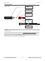
1
SF6 P1:p Instrument User Manual V1.1 Unrivalled Detection. www.ionscience.com SF6 P1:p MANUAL Ion Science Ltd Register your instrument online for extended warranty Thank you for purchasing your Ion Science instrument. The standard warranty of your instrument can be extended to up to two years on PhoCheck Tiger and two years on other Ion Science instruments. To receive your extended warranty, you must register your instrument online within one month of purchase (terms and conditions apply.) Visit www.ionscience.com/instrument-registration Part number: SF6 P1:p MANUAL Ion Science Ltd Declaration of conformity Name und Adresse des Herstellers / Manufacture´s name and address / Nom et adresse du fabricant ISM Deutschland GmbH, Laubach 30, D-40822 Mettmann, Germany Die ISM Deutschland GmbH bescheinigt die Konformität für das Produkt / The ISM Deutschland GmbH declares conformity of the product / ISM Deutschland GmbH dérclare la conformite du produit Bezeichnung / Product name / Designation: SF6-Lecksuchgerät / SF6-Leakseeker / Les détecteuers de fuite SF6 Typ / Type / Type: SF6 LEAKCHECK P1:p Mit den folgenden Bestimmungen / with applicable regulations / avec les directives suivantes EMV Richtlinie 89/336/EWG ergänzt durch 91/263/EWG, 92/31/EWG EMC Drective 89/336/EEC amended by 91/263/EWG, 92/31/EEC Directive EMC 89/336/CEE amendée par 91/263/EWG, 92/31/CEE Niederspannungsrichtlinie 73/23/EWG ergänzt durch 93/68/EWG Low-Voltage Equipment Directive 73/23/EEC amended by 93/68/EEC Directive des equipements basse tension 73/23/CEE amendée par 93/68/CEE Angewendete harmonisierte Normen / Harmonized standards applied / Normes harmonisées utilisáes Sicherheit / Safety / Sécurité EN 61010-1 : 1993 / IEC (CEI) 1010-1 : 1990 A 1 : 1992 / VDE 0411: 1994 Überspannungskategorie / Overvoltage category / Catégorie de surtension: II Verschmutzungsgrad / Degree of pollution / Degré de pollution: 2 Elektromagnetische Verträglichkeit / Electromagnetic compatibility / Compatibilité electromagnétique EN 50082-2: 1995 / VDE 0839 T82-2 ENV 50140 : 1993 / IEC (CEI) 1001-4-3 : 1995 / VDE 0847 T3 ENV 50141 : 1993 / IEC (CEI) 1000-4-6 / VDE 0843 / 6 ENV 61000-4,2 : 1995 / IEC (CEI) 1000-4-2 : 1995 / VDE 0847 T4-2: Prüfschärfe /Level / Niveau = 2 EN 61000-4-4: 1995 / IEC (CEI) 1000-4-4: 1995 / VDE 0847 T4-4: Prüfschärfe /Level / Niveau = 3 EN 50081-1 : 1992 / EN 55011 : 1991 / CISPR11 : 1991 / VDE0875 T11 : 1992 Gruppe / group / groupe = 1, Klasse / Class / Classe = B Datum / Date / Date 17.10.2001 Unterschrift / Signature / Signatur Hr. Becker – Technical Director Unrivalled Detection. 2 of 41 www.ionscience.com SF6 P1:p MANUAL Ion Science Ltd Contents Declaration of conformity ............................................................................................................................... 2 Remarks ............................................................................................................................................................ 4 Target group ................................................................................................................................................... 4 General information........................................................................................................................................ 4 Safety instructions .......................................................................................................................................... 4 Correct use ..................................................................................................................................................... 4 New design handset ....................................................................................................................................... 4 Versions ............................................................................................................................................................ 5 SF6 LEAKCHECK P1:p – Portable case instruments ................................................................................... 5 Usage in practice ............................................................................................................................................. 6 For leak detection ........................................................................................................................................... 6 For leak measurements ................................................................................................................................. 6 For concentration rise measurements (integral atm.) .................................................................................... 6 System properties ........................................................................................................................................... 7 General properties ......................................................................................................................................... 7 Measuring principle ........................................................................................................................................ 7 Measurement reliability .................................................................................................................................. 7 Control and display elements ........................................................................................................................ 8 Control and display elements on the base unit .............................................................................................. 8 Control and display elements on the handset ................................................................................................ 9 Putting into operation ................................................................................................................................... 11 Operation modes ........................................................................................................................................... 12 Search Mode ................................................................................................................................................ 12 Measuring Mode .......................................................................................................................................... 12 Operation ........................................................................................................................................................ 13 Ready for measuring .................................................................................................................................... 13 Saving of measurement data ....................................................................................................................... 13 Possible malfunctions when starting the system ......................................................................................... 14 Possible malfunctions during operation ....................................................................................................... 14 Turning off ...................................................................................................................................................... 16 Switching off when there is a failure ............................................................................................................ 16 Setting up the operating parameters ........................................................................................................... 17 Entry of passwords and numbers ................................................................................................................ 17 Activating the operating mode menu ........................................................................................................... 17 Setting volume and screen contrast ............................................................................................................. 18 Operator level ............................................................................................................................................... 18 The technical level ....................................................................................................................................... 19 The supervisor level ..................................................................................................................................... 26 Service life of the SmartSensor ................................................................................................................... 28 Exchanging the SmartSensor ...................................................................................................................... 29 Known problems ............................................................................................................................................ 30 Calibration in the ppm mode ........................................................................................................................ 30 Calculating the concentration ....................................................................................................................... 30 Accessories .................................................................................................................................................... 31 Sniffer probe extension ................................................................................................................................ 31 Leads extender ............................................................................................................................................ 32 SF6 Leak Detector Calibrator ...................................................................................................................... 32 Filter replacement .......................................................................................................................................... 33 Technical data ................................................................................................................................................ 34 Error messages .............................................................................................................................................. 35 Notes ............................................................................................................................................................... 39 Instrument warranty and service ................................................................................................................. 40 Contact details ............................................................................................................................................. 40 Manual log ...................................................................................................................................................... 41 Unrivalled Detection. 3 of 41 www.ionscience.com SF6 P1:p MANUAL Ion Science Ltd Remarks Target group This Instruction Manual is intended for operators who perform operation-specific settings on the SF6 LEAKCHECK P1:p leak detectors. General information The Instruction Manual applies to the software version stated in the header (e.g. V3.06). Safety instructions Before you use the instrument, please read and comply with these instructions: – Keep the Instruction Manual in a safe place. – Only ISM employees may open the instrument or parts of it. – There are no components in the instrument that require maintenance. – Protect the instrument from moisture. – Use the instrument only in dry places. – Only use earthed systems that are without current. Correct use The P1:p leak detectors are intended only for detecting leaks and making measurements on components filled with SF6 or FM-200. Any other use is considered as incorrect. New design handset Only handsets from and including serial number 00125 upwards can be operated in connection with the SF6 LEAKCHECK P1:p. The serial number of the handset can be read off from underneath the grip part. For this, push the grip part slightly upwards. Unrivalled Detection. 4 of 41 www.ionscience.com SF6 P1:p MANUAL Ion Science Ltd Versions SF6 LEAKCHECK P1:p – Portable case instruments SF6 LEAKCHECK P1:p Standard Detection limit: 1 x 10E-7 ml/s 1.0 ppm SF6 LEAKCHECK P1:p HIGHsens Detection limit: 1 x 10E-8 ml/s 0.1 ppm Unrivalled Detection. 5 of 41 www.ionscience.com SF6 P1:p MANUAL Ion Science Ltd Usage in practice Owing to the practice-oriented design of the instruments, work with these is simple and reliable when observing the following: For leak detection Switch the instrument to the Search Mode (Chap. 0, “ - Search Mode“, Page 12). - Guide the sniffer probe as closely as possible to the suspected leaking locations. Establishing material contact with the sniffer probe will be useful. - The velocity at which the sniffer probe is advanced should be at about 20 mm/s. - Please do not push the sniffer probe over the test specimen, but pull it instead so as to effectively prevent the ingress of grease and dirt, for example. For leak measurements Switch the instrument to the Measurement Mode (Chap. 0, “ - Measuring Mode“, Page 12). Observe the displayed unit of measurement (cc/s or g/a) which is desired. - Guide the sniffer probe as closely as possible to the suspected leaking locations. Establishing material contact with the sniffer probe will be useful. - The magnitude of the leak can be considered as being correctly acquired when the measured value does not change within 2 seconds. For concentration rise measurements (integral atm.) In the user set-up select the unit of measurement “ppm”. - Place the test specimen within the chamber free of SF6, close the chamber. - Zero the leak detector in clean ambient air by operating the “Zero” button. - For the initial measurement with the P1:p leak detector, push the sniffer probe for approximately 10 to 20 seconds through a corresponding connection directly into the chamber. Save the measured concentration (red triangle button). Remove the sniffer probe from the chamber. - After the measurement time defined by the customer has elapsed, Zero the leak detector in clean air by operating the “Zero” button, introduce the sniffer probe into the chamber again and perform the final measurement for a duration of approximately 10 to 20 seconds. Save the measured concentration (red triangle button). Remove the sniffer probe from the chamber. The difference between the two saved measured values gives the rise in concentration within the measurement time specified by the customer. Unrivalled Detection. 6 of 41 www.ionscience.com SF6 P1:p MANUAL Ion Science Ltd System properties General properties The P1:p leak detectors are rugged, mains power independent instruments for leak detection and leek measurements involving electron capturing gases, SF6 in particular. All necessary operating and display elements have been combined in the handset. The quantitative determination of a leak is performed through the numeric display on the screen of the base unit (P1:p case cover). For documentation purposes, measured values can be saved, subsequently reviewed on the screen and printed out or transferred to a computer. All components subject to wear have been combined in the exchangeable ISM SmartSensor. Base unit and handset will not require any maintenance or care except for external cleaning from time to time. Worn out sensors are replaced. During leak searching, the operator is supported through the following facilities: 1. An easy to read pointer gauge, which, depending on the operating mode indicates the measured value by way of a percentage of the preset limit, thus excluding the possibility of any incorrect interpretation, or (in the Search Mode) a full-scale response is attained whenever a leak is detected. 2. The peak-hold function for the pointer gauge which can be programmed to an adjustable time or for manual deleting. 3. A vibration alarm which lets the handset vibrate noticeably as soon as a certain limit is exceeded. 4. A notification LED which comes on as soon as the measured value exceeds 20% of the preset limit and which can be reset by operating the Zero button or the Save button. 5. A differentiated audible alarm, enabling unrestricted leak searching even at inaccessible places, when you cannot see the display. Measuring principle © A further developed high-voltage ionization detector (NIC ) is used and which has been optimised in consideration of the following: – sensitivity – precision – service life – reliability Through miniaturisation it has been possible to accommodate the sensor directly in the measurement tip, thereby attaining excellent response and recovery timings. Measurement reliability The processor constantly monitors all operating values relevant for the measurements, and, if necessary, adjusts them. For example, drift of the sensor and reducing air permeability of the front filter are compensated for. Proper operation of the SmartSensor is only possible under constant and precise control through the software. For this reason there exists a closed signal loop from the processor, over the high-voltage generator, the sensor itself and the processing circuitry back to the processor. A fault at any place within this loop will immediately cause the sensor signal to fail resulting in an error message. Together through monitoring of the taken in the airflow, the possibility of the worst conceivable fault condition is excluded: An instrument which presents itself to the operator as being ready but which actually is incapable of “seeing” existing leaks. Programmable parameters which have an influence on the measurements, are protected through password queries within the different levels against unauthorised or inadvertent changes. Access to the LCD touch screen is only necessary when wanting to change the programming. Unrivalled Detection. 7 of 41 www.ionscience.com SF6 P1:p MANUAL Ion Science Ltd Control and display elements Control and display elements on the base unit Located at the base unit are the following elements: 1. LCD touch screen for numeric display of the leak rate as well as for entering parameters. 2. P1:p the On/Off button, illuminated red when the instrument has been switched on. 3. White mains and charging indicator lamp. It flashes while the built-in rechargeable battery is being charged after having connected the instrument to the mains power supply. As soon as the battery has been fully charged, the light stays on constantly, without mains power it remains off. LCD touch screen On/Off button Mains power and charging light Unrivalled Detection. 8 of 41 www.ionscience.com SF6 P1:p MANUAL Ion Science Ltd Control and display elements Control and display elements on the handset The handset is equipped with the following display elements: 1. The pointer gauge for displaying the currently measured value. In the Search Mode the gauge will either indicate only “Zero” or “Full scale”. In the Measuring Mode the currently measured leak rate is indicated. Instead of an absolute value, the leak rate is indicated in percent of the preset limit thereby excluding any possibility of misinterpreting the displayed values. Example: Alarm preset: ................. 10 E-7 ml/s, Current meas. value: ....... 8 E-7 ml/s, Analogue readout: ......... 80%. The corresponding absolute value may in the Measuring Mode be read off from the display of the base unit. 1 4 2 5 3 6 Six LEDs are provided to indicate the different operating modes: COLOUR NUMBER Description 1 READY FOR MEASURING. Is turned off when the instrument is in the programming or standby mode or when a fault is present. Flashes in the Search Mode. 2 NOT READY FOR MEASURING. Is turned on when the instrument is in the programming mode or if a fault is present. Flashes in the Standby Mode 3 SPECIAL. For additional custom functions. Currently the LED will flash when selecting the extended display range. 4 SIGNAL. Is on when a measured value has exceeded 20% of the preset limit. Is turned off after operating the Zero or memory button. 5 ALARM. Is on as long as the measured value reaches or exceeds the preset limit. 6 MESSAGE. Requests the operator to read a message indicated on the display. Unrivalled Detection. 9 of 41 www.ionscience.com SF6 P1:p MANUAL Ion Science Ltd Control and display elements 3. The three control buttons: This button has two functions: 1) When pressing this button for a long time, the system switches between Search and Measuring Mode. For this, the button is pressed until the red “STATUS” LED is turned off again. Before switching over, the instrument performs a Zero setting so that there will be a short delay. 2) IN THE MEASURING MODE ONLY: Pressing this button briefly will expand the display range of the analogue pointer gauge of the handset. Pressing this button once will select factor 1 set up in the user setup (green “SPECIAL” LED flashes slowly). Pressing this button once more selects factor 2 (green “SPECIAL” LED flashes rapidly). When pressing this button once more briefly, or pressing the Zero button, the SF6 LEAKCHECK P1:P will switch back again to the normal display mode. Setting of the measured value to Zero. For a brief moment the LED indicator will change from “READY “ to “NOT READY”. Since during this time and if necessary the energy flow to the sensor is corrected, the Zero button should be in any case operated from time to time even if no deviation from the Zero level is present. When the extended display range is active, it will also be disabled. IN THE MEASURING MODE ONLY: The peak value indicated on at the bottom on the right of the screen is saved and thereafter set to Zero. Saved values may later be output through the serial interface to a computer or printer. Pressing this button for a long time, displays the option “Data Memory Control” serving the purpose of administrating saved measured values. Unrivalled Detection. 10 of 41 www.ionscience.com SF6 P1:p MANUAL Ion Science Ltd Putting into operation Preparations for putting the P1:p leak detectors into operation are limited to connecting the handset, the sensor, and, if available, the mains power. When connecting the handset and the sensor you must ensure that the markings on the plug and socket the line up with each other and that the slide piece of the plug has reached the locking position, in which it is completely in contact with the collar of the socket. When briefly pressing the red On/Off button, the instrument will start. Approximately 20 to 30 seconds after the start-up screen has been displayed, the normal operating screen will be displayed. Should this not be the case, then please read the message on the screen as well as the information provided in the Chapter "Possible malfunctions when starting the system" and "Switching off when there is a failure". „Search Mode“ display Start screen „Measuring Mode“ display Unrivalled Detection. 11 of 41 www.ionscience.com SF6 P1:p MANUAL Ion Science Ltd Operation modes The P1:p leak detectors offer two different measurement operating modes which are explained in the following. The user himself may define the mode which will be enabled when switching the instrument on. During operation it is possible to change between the modes at any time by pressing the green SQUARE button for a longer time until the red LED “Not READY” on the handset lights up again. Search Mode In the Search Mode, the instrument operates with the greatest possible sensitivity. However, there is no quantitative display of leaks. Instead, each leak which is found results in a full scale response of the analogue gauge in the handset as well as a corresponding audible alarm. For approximately estimating and locating the leak, there is a bar display on the screen. The advantage of the Search Mode is the fact that even small leaks or leaks not completely determined are not easily "overlooked“. Moreover, by dispensing with a quantitative readout, sensitivity is, compared to the Measurement Mode even slightly higher. The Search Mode is indicated on the bar display of the screen as well by flashing of the “READY" lamp on the handset. Measuring Mode In the Measuring Mode, the leak rate is indicated on the screen using large digits. The gauge on the handset indicates the measured leak rate in percent of the limit. Therefore a leak which is as great as the selected limit will give a readout of 100%. In the Measuring Mode, the green “READY” lamp will be on constantly. In this operating mode, it is possible through the “User Setup” to select and indicate the required unit of measurement (cc/s, g/a, ppm). Unrivalled Detection. 12 of 41 www.ionscience.com SF6 P1:p MANUAL Ion Science Ltd Operation Ready for measuring The P1:p leak detectors are ready when the “Search Mode” bar is visible on the screen or in “Measuring Mode” the large digits of leak rate display are visible. This situation comes about only, if: 1. the SmartSensor functions within its operating limits, 2. the suction airflow is within the nominal range, and 3. as long as the continuous self tests run successfully. At the same time, the “READY” lamp lights up on the handset. In the Search Mode, this lamp flashes when the instrument is ready for measuring. Saving of measurement data The leak detectors are capable of separately saving the measurement data for several test specimens and outputting such data through the serial interface to a printer or a computer. Saved data is also retained when switching the instrument off. The memory capacity permits 100 measured data for a maximum of 96 different test specimens. Saving of a measured value is only possible in the Measuring Mode, since in the Search Mode no quantitative measurements are run. Briefly pressing the red TRIANGLE button on the handset will save the highest measured value which has occurred. This highest value is displayed on the screen at the bottom on the right under “PEAK:”. Each time a value is saved or after zeroing, the peak memory is erased and will be ready to accept the next measured value. Using the measured value memory As to the internal processing of the peak memory, the following applies: Upon pressing the red TRIANGLE button, the value of the peak memory indicated on the screen is carried over by way of a new entry to the dataset for the test specimen. - The peak memory as indicated on the screen is simultaneously erased and ready to accept the next measurement. - By operating the yellow Zero button, the peak memory is also erased. - A dataset for a test specimen can be “open” or “closed”. Only one test specimen dataset can be open at a time. New data is always written to the opened test specimen dataset. A closed test specimen dataset cannot be opened again. - An opened test specimen dataset is closed when: - - the programme section “User Setup” is activated - a new worker test specimen identifier is entered (simultaneously opening a new test specimen dataset) - the measurement data memory is erased - a new test specimen dataset is opened manually - or the instrument is switched off. A new test specimen dataset is automatically opened, when - the TRIANGLE button is operated and when currently no test specimen dataset is open. This will always be the case after having switched the instrument on - a new worker or test specimen identifier is entered. Unrivalled Detection. 13 of 41 www.ionscience.com SF6 P1:p MANUAL Ion Science Ltd Operation On the operator level (OPERATOR LEVEL) a variety of administration functions for the data and the memory are available. The basic functions like “Start print out”, “Open new test specimen dataset” and “Erase data memory” can be invoked also through the buttons of the handset. In contrast to earlier versions of the P1:p leak detectors, the data is not automatically deleted after a successful print out. Instead the data is retained until being deleted manually. The operator should, for this reason, before starting a new measurement run, not forget to delete the “old” data. In each test specimen dataset the following information is also saved besides the actual measurement data: - The serial number of the leak detector - The unit of measurement selected for the display at the point of time of the measurement - The type of gas (SF6 or FM-200) selected at the point of time of the measurement - Creation time and date for the test specimen dataset - Optionally, a worker identifier - Optionally, a test specimen identifier, serial or batch number, for example - The leak rate limit applicable when taking the measurement - The total of all saved measured values (total leak rate). For each individual measured value, the time of the measurement as well as any apparent exceeding of the limit are also printed out. The output is effected in the text format through the serial interface. If instead of a printer, a computer is to receive the data, then a so-called Null Modem Cable must be used where the signal lines are crossed. The transmission format is 9600-8-N-1 (9600 baud, 8 data bits, no parity, 1 stop bit). When using a printer, the leak detector must be set up for the same handshake as used by the printer (0 Handshake ), so that the printer can control the data flow. For this please also refer to the manual of your printer. On the supervisor level (SUPERVISOR LEVEL) the entry of a worker or test specimen identifier can be made mandatory. When such entries have been made mandatory, the instrument will query the entries upon opening a new test specimen dataset. Also if such entries are not made mandatory, such entries can be entered at any time, however, the operator is not asked to do so. The information relating to the identification, needs to be entered BEFORE creating the test specimen dataset in which it shall appear. Possible malfunctions when starting the system Most severe errors are already detected and indicated upon switching the instrument on. Running up of the instrument is then interrupted and a corresponding error message is indicated. At the bottom of the screen, a countdown will run which switches the instrument off after 15 seconds. This countdown can be cancelled through the [ STOP ] button. After operating this button, its designation changes to [ EXIT ] allowing the operator to enter the menu system where he may then change settings, read out technical data or run a diagnosis. Inasmuch as the displayed message is not self-explanatory, please get in touch with ISM or your ISM certified distributor stating the kind of error message so as to allow the malfunction to be analysed. If an error message relating to the SmartSensor is encountered, please always first exchange the SmartSensor. Possible malfunctions during operation If during operation a relevant malfunction occurs, the display on the handset will change from “READY” to “NOT READY”, and the “MESSAGE” lamp will light up indicating to the operator to read the error message displayed on the screen and if required acknowledge it. Unrivalled Detection. 14 of 41 www.ionscience.com SF6 P1:p MANUAL Ion Science Ltd Operation The following error messages can occur: LOW SAMPLE FLOW (low intake air flow) When blocking the air intake opening of the sensor totally or partly, an error message is produced requesting the operator to check the condition of the sensor. Two buttons are available to confirm this error message: [RESTART]requests the instrument to try and resume measurement operation. For this, the operating vacuum is controlled anew. If unsuccessful, then the error message will appear again after a short while. [ POWER DOWN ] switches the instrument off so as to allow the sensor to be replaced. The selection can also be performed through the buttons of the handset. Corresponding symbols are displayed in the buttons on the screen. TOO MUCH GAS (failure of the discharge in the SmartSensor) For this kind of malfunction there are two possible causes: 1. a very high concentration of detectable gas, 2. an operating vacuum which is too high due to a worn out or partially blocked SmartSensor. Since the quantity of taken in air is maintained at a constant level, a reduction in the air flow through the filter or the intake opening will result in an increased operating vacuum. When the operating vacuum is found to be much increased, the discharge in the SmartSensor becomes unstable and can fail. 3. A malfunction in the SmartSensor caused by contamination within the ionization chamber can also cause the discharge to fail. The operator is then requested to remove the SmartSensor from the possible gas source and confirm this by pressing a button. After having acknowledged the condition, the discharge is, if possible, reignited and controlled. If this is unsuccessful or if the error message appears without any apparent reason, then please replace the SmartSensor. PUMP RATIO HIGH (overloading of the suction pump) This error condition is detected when the suction pump must run significantly more frequently or longer than expected so as to maintain the operating vacuum. The reason for this can be a leak in the pneumatic system of the leak detector or a malfunction affecting the suction pump. Since in any case the reliability of the measurement is endangered, the options [ DIAGNOSTICS ] (change to the diagnosis screen) or [ POWER DOWN ] (shut down) are offered to the operator. LOW BATTERY VOLTAGE If without a mains power connection being present, the voltage of the rechargeable battery reaches the total discharge level threshold, the user is informed as to the imminent shutdown. If no mains power is available, operation can be continued for a short while, however, from now on the instrument may shut down itself at any time so as to avoid damaging the rechargeable battery. Unrivalled Detection. 15 of 41 www.ionscience.com SF6 P1:p MANUAL Ion Science Ltd Turning off When switching off, the processor of the instrument powers down in several steps. Here, among other things, the non-volatile memories of the sensor, the handset and the base unit are updated. In order to turn off the instrument, the red ON/OFF button must be pressed for several seconds. Running of this holding time is indicated on the screen through a time bar. When releasing the button before the holding time has elapsed, then the instrument will return to normal operation. After the holding time has elapsed, the screen will indicate “GOODBYE”, and the button may now be released. Switching off when there is a failure Normally the processor will control the turning off process as described above. Should, owing to a severe malfunction, this process no longer be operational, then the instrument can be de-energised in spite of this by a forced hardware controlled shutdown. For this the On/Off button needs to be depressed for approximately 8 seconds until the forced shutdown has occurred. Unrivalled Detection. 16 of 41 www.ionscience.com SF6 P1:p MANUAL Ion Science Ltd Setting up the operating parameters Described in this section are the parameters which define the behaviour of the P1:p leak detectors as well as the procedures for setting up the parameters. All parameters are protected by passwords against unauthorised or inadvertent changes. Three groups of related parameters can be protected by different passwords: - The operator level (OPERATOR LEVEL) contains settings and entries which can be accessed by the worker during measurement operation. These include entries for operator and test specimen identification as well as functions for administration of the measurement data memory. - The technical level (TECH. LEVEL) contains besides settings which define the way in which the leak detector responds, also reading out of technical data for support and after sales service as well as the calibration process and the entry of the limits. - The supervisor level (SUPERVISOR LEVEL) finally ensures administration of the passwords as well as the settings relating to mandatory worker and test specimen identification entries. Through different passwords, each functional group can be made accessible to a certain range of persons. Entry of passwords and numbers At several points within the menu system, the entry of passwords and numbers is required. For this, in each case a 10 digit keypad or an alphanumeric keypad is displayed. For entering, simply touch the required number or letter keys. Incorrect entries may be corrected through the [ <- ] button, upon which the character which was entered last is deleted. To end the entry process, please use the RETURN button. In the case of many entries, the current value of the parameter is displayed by default. You may then simply confirm this value by operating RETURN or enter it anew. Through the [ <- ] button, also partial deletions are possible. The [ ESC ] button cancels the entry process and any changes made so far rejected. Activating the operating mode menu When the instrument is running in the Search Mode or in the Measuring Mode (large display of the leak rate) then the main menu may be invoked by touching the touch screen anywhere. From here further menu sections can be accessed by touching the displayed buttons. Returning to the Measuring Mode is effected by operating the [ EXIT ] (End) buttons shown on all of the screens. In the following description of the individual setting up functions, it is assumed that the main menu has already been invoked. Branch offs are indicated by stating the [Buttons] which need to be touched in square brackets and blue colour. Displayed (screen messages) are shown in round brackets. Unrivalled Detection. 17 of 41 www.ionscience.com SF6 P1:p MANUAL Ion Science Ltd Setting up the operating parameters Pre-set passwords in the delivered state In the delivered state, all passwords have been preset to “000”. Details on how to change passwords are provided in Chapter. Setting volume and screen contrast [ SET VOLUME / CONTRAST ] Through the buttons [ + ] and [ - ] it is here possible to change the volume of the sound output (separately for base unit and handset) as well as the screen contrast. Operator level (OPERATOR LEVEL) In the operator level all functions have been combined which are accessible to the worker during measurement operation. The operator level is reached from the main menu through the button [ OPEN OPERATOR LEVEL ] and thereafter entering the operator password. Entry of worker identification [ OPEN OPERATOR LEVEL ] / [ OPERATOR ID ] If on a subsequent data print out an identification of the worker shall appear, then here a name or a corresponding identifier can be entered. If the entry of a worker identification has been made mandatory then this entry screen will be displayed automatically upon opening a new test specimen data set . Also when the entry has not been made mandatory, the identifier can be entered at any time during operation. This must be done BEFORE opening the test specimen dataset in which the identifier shall appear. Entry of test specimen identification [ OPEN OPERATOR LEVEL ] / [ PRODUCT ID ] If on a subsequent data printout an identification of the test specimen shall appear, then here a batch or serial number can be entered. If the entry of a test specimen identification has been made mandatory then this entry screen will be displayed automatically upon opening a new dataset. Also when the entry has not been made mandatory, the identifier can be entered at any time during operation. This must be done BEFORE opening the test specimen dataset in which the identifier shall appear. Printing stored data [ OPEN OPERATOR LEVEL ] / [ DATA PRINTOUT ] If during the measurement, data has been saved by operating the TRIANGLE button at the handset, then here outputting of the saved data through the serial interface can be initiated. If there exist data for several test specimens in the memory, then a selection screen is displayed before the printing process starts where the test specimen data sets which are to be printed can be selected. The button [ GO ] starts the printing process, the button [ EXIT ] cancels the process and returns to the Measuring Mode. Viewing of the saved data is possible through [ DATA MEMORY CONTROL ]. Data memory administration [ OPEN OPERATOR LEVEL ] / [ DATA MEMORY CONTROL ] This function can also be reached from the Measuring Mode (NOT the Search Mode) by pressing the red triangle button longer. The more important options available here can also be controlled through the buttons of the handset. Because of this it is possible during measurement operation to keep the transparent cover of the touch screen closed and secured. Symbols corresponding to the buttons on the handset are displayed in the respective buttons. From here all administration functions for the measured data memory can be controlled. In addition, a summary of the current memory usage is shown at the bottom of the screen. The individual buttons are: [ DATA PRINTOUT ] (or yellow circle button). Starts a printout of the saved measurement data through the serial interface. Before, the test specimen date sets which are to be printed out can be selected. When starting this through the button on the handset, no selection is possible, in this case the entire memory contents are printed. Unrivalled Detection. 18 of 41 www.ionscience.com SF6 P1:p MANUAL Ion Science Ltd Setting up the operating parameters [ NEW COMPONENT ] (or red TRIANGLE button). Measurement data for several test specimens can be saved. The button [ NEW COMPONENT ] opens a new blank test specimen dataset. For a maximum number of 96 test specimens 100 measurement data for each can be saved. If the entry of a worker or test specimen identification has been made mandatory, the entry of this data is queried automatically. [ CLEAR DATA MEM. ] (or simultaneously SQUARE and TRIANGLE button). This deletes all saved measured values. This function should be utilised before starting any new measurement run so as to remove possibly present values which are no longer valid. Upon initialisation through the screen, a safety query is displayed before erasing the data. Upon initiation through the buttons on the handset, there will be no such query since inadvertent operation is not possible. [ VIEW DATA ] Viewing saved data on the screen. In the data area of the screen, the measured values may be scrolled upwards and downwards using the arrow buttons. In the operator area information on the respective test specimen dataset as well as the buttons for selecting the displayed test specimen dataset is available. The technical level (TECH LEVEL) On the technical level, functions like running of the final calibration, operator-specific settings and reading of technical data have been combined. From the main menu, the technical level is accessed through the button [ OPEN TECH. LEVEL ] with subsequent password entry. The functions which are available on this level are: Final calibration [ OPEN TECH. LEVEL ] / [ CALIBRATION ] With the aid of the final calibration, the accuracy of the quantitative determination of leaks can be improved compared to the system calibration. In the course of the final calibration, the actual value of the calibration leak, respectively the concentration of the calibration gas must be entered. If always the same calibration leak/calibration gas is used, this entry will be required only once. The value is saved by the instrument and only needs to be confirmed by the operator by pressing RETURN. Separate memory locations are available for the calibrated values for each operating mode. Therefore, when changing between operating modes, the actual value will not have to be entered once more. When entering a new value, it may possibly required to convert the actual value stated on the calibration leak to the unit of measurement used by the P1:p (E-7cc/s, E-8cc/s, ppm or gm/yr). After acknowledging the entry, the actual calibration process is run. The instrument first determines the background level. For this the sniffer probe must be placed in the air of the room which is free of SF6. The message “Calibrating clean air:” and a time bar are displayed. After the time on the time bar has elapsed, the operator is requested to guide the SmartSensor to the calibration leak. The corresponding time bar will only start to run after this has been done. During the measurement, the intake opening of the SmartSensor must be constantly held precisely at the opening of the calibration leak. If this is not done, then there is the risk of producing a faulty calibration. The measurement can be cancelled at any time through the [ E X IT ] button. Then the instrument returns to the Measuring Mode, and the previous calibration remains unchanged. Use this possibility when wanting to enter the actual value of your calibration leak/calibration gas but without wanting to run a calibration. After the calibration has been completed, the operator is requested to remove the sensor from the calibration leak. The new calibration factor is displayed. If the factor is outside the permissible range, then the leak detector will assume an error during the calibration. Such errors may, for example, be due to removing the sensor from the calibration leak during the process or missing agreement of the entered actual value with the value of the calibration leak. In this case the new calibration factor is rejected and the initial calibration factor is maintained. An acceptable new calibration factor is marked by a check mark and an unacceptable calibration factor is marked by a warning triangle. Unrivalled Detection. 19 of 41 www.ionscience.com SF6 P1:p MANUAL Ion Science Ltd Setting up the operating parameters Setting date and time [ OPEN TECH. LEVEL ] / [ SET CLOCK ] The built in real time clock supplies time marks to saved measured values and calibration data, and should for this reason be corrected in the case of noticeable deviations. Setting the real-time clock can become necessary under the following circumstances: – Daylight saving time change – Transportation to a different time zone – Normal running deviation – When the instrument was separated from the built-in rechargeable battery. Through [ NEXT ] select day, month, year, hour or minute to be changed and then set through [ + ] and [ - ] the desired value. Upon exiting the entry through [ E XI T ] the real-time clock is updated with the new values. User specific settings [ OPEN TECH. LEVEL ] / [ USER SETUP ] In the User Setup, different parameters have been combined which are described in the following. To change a parameter, first the inverted entry cursor needs to be placed on the corresponding line using the arrow keys. Through the buttons [ + ] and [ - ] the value may then be changed within the permissible range. When exceeding the upper limit of the valid range, the entry then skips to the lower range limit and vice versa. Display operating mode (DISPLAY UNITS) The numerical display on the screen as well as the entries for the limits and actual values for calibrations are output in the unit of measurement selected here. For the different display operating modes, there exist for all these values as well as for the calibration factor separate memory locations. Therefore when changing between the display modes “ppm”, “gm/yr” and “cc/s” these will not have to be entered once more. Currently the following display modes are available: - E-7 cc/s (leak rate, corresponds to ml/s – mbarl/s) - E-8 cc/s (leak rate) only for HIGHsens instruments - ppm (concentration) - gm/yr (leak rate). The display operating mode “ppm” is special. Since it requires a higher sensitivity compared to the other modes, and since on the other hand the response and recovery times during concentration measurements are irrelevant, an additional low pass filter has been placed in the signal path of this display mode. This filter smoothes the measured signal, blocks short-term fluctuations thereby ensuring a smooth reading. In the case of concentration measurements you will, for this reason, have to expect significantly longer response and recovery times, which, depending on the measured concentration, can amount to up to 10 seconds. Moreover, in the “ppm” display operating mode, the Search Mode is not available, since the extended response time does not agree with the intentions of the Search Mode. Peak hold function of the pointer gauge ( PEAK HOLD (GAUGE) ) Owing to the short recovery time of the P1:p, this function is useful during leak detection. The current peak value is held for the preset time by the pointer instrument of the handset. In the OFF position, this function is switched off, position MANUAL requires deleting of the peak value by pressing the Zero or the memory button at the handset. Start-up measurement mode ( STARTUP MODE ) Here it is possible to define which mode (Search Mode or Measurement Mode) the instrument shall run after switching on. During operation of the instrument, it is possible to change at any time between the two modes. Unrivalled Detection. 20 of 41 www.ionscience.com SF6 P1:p MANUAL Ion Science Ltd Setting up the operating parameters Screen appearance ( SCREEN APPEARANCE ) The screen display is selectable either to white on black or black on white. Language selection ( LANGUAGE ) This option is reserved for future extensions, currently only English is available as the operator language. In coordination with ISM also other languages can be implemented. Entry of the alarm limit ( ALARM LEVEL ) Here enter the desired limit for the active display operating mode. As soon as this limit is reached, the pointer instrument of the handset will indicate 100%, and the “ALARM” LED comes on. Saved measured values which are above this limit, are clearly marked in the data printout. The units of measurement in the active display mode are shown as a reminder in the entry area. In order to change the limit for a different display mode, this display mode will have to be activated first. The instrument remembers the limits separately for each display mode so that when changing the display mode they will not have to be entered anew. It may possibly be required to convert the entered value in consideration of the currently displayed unit of measurement. The entry may if required, being effected including decimal places. Threshold for the sound signal during measurements ( WARNING BEGINS AT ) This setting defines the threshold upon which the sound signal as well as the vibration alarm during the measurements set in. Both set in when the measured value exceeds the limit by the entered percentage. In the case of the setting NO WARNING, no sound signal nor vibrations are produced during the measurement. Sound warning signals in the case of error conditions are not affected by this setting. For leak detection purposes we consider a setting of approximately 20 to 50% as sensible. In practice not every leak is immediately acquired in full and could be overheard at higher settings. Vibration alarm on/off ( HAND UNIT VIBRATION ) When this parameter is set to OFF, then the vibration alarm of the handset is disabled. Display factor 1 analogue gauge in the handset ( DESENS. FACTOR 1 ) Functions only in the measurement mode. Permits pinpointing of larger leaks where full scale of the analogue gauge is quickly reached. By operating the green SPECIAL button once, the display range is expanded by the entered factor. In the case of an active factor of 1, the green “SPECIAL” LED will flash slowly. Display factor 2 analogue gauge in the handset ( DESENS. FACTOR 2 ) Functions only in the measurement mode. The display range is expanded by the entered factor by operating the SPECIAL button twice. With the setting OFF, selection of Desens Factor 2 is disabled. In the case of an active Factor 2, the green “SPECIAL” LED will flash rapidly Note: The display factors will only affect the analogue gauge and the sound output, not however, the numeric display. For this reason also such values can be saved and printed out which have been saved while the display was in the extended mode. Selection of the standby operating mode ( STANDBY MODE ) A motion sensor in the handset permits automatic shutting down of the leak detector fully or partially during operating breaks. When the handset is not moved within a preset period of time, one of the standby operating modes described in the following is enabled. Running of the standby mode is indicated at the handset by a slowly flashing red LED “NOT READY”. When moving the handset again, the instrument will resume full operation (exception: setting POWER DOWN). Unrivalled Detection. 21 of 41 www.ionscience.com SF6 P1:p MANUAL Ion Science Ltd Setting up the operating parameters Returning to normal operation can also be effected by operating one of the buttons on the handset or by (briefly!) pressing one of the On/Off buttons. - NONE: Standby operation is disabled. - LIGHT: The screen illumination is switched off. This extends the battery operating time and conserves the fluorescent lamp behind the screen (service life according to the manufacturer: 10,000 hours). The instrument remains unconditionally ready for measurements, there is no warning before the instrument enters the standby mode. - LIGHT AND SENSOR: Both the illumination behind the screen, the discharge in the sensor as well as the flow controller are switched off, the operating vacuum is decayed. Thus all system components, however, the sensor in particular, are spared and above all protected against “silent wear”. This condition differs from that of a complete shutdown, in that the instrument is capable of restarting when picking up the handset. Before enabling this standby operating mode, a sound signal and a note on the screen with a time bar are generated. During the running time of the time bar of 20 seconds, it is possible to cancel the process and return to the measurement mode by moving the handset or pressing one of its buttons. - POWER DOWN: The instrument shuts down completely. If longer operating brakes are to be expected, especially in the case of mains independent operation, this setting should be preferred. Before enabling this standby operating mode, a sound signal and a note on the screen with a time bar are generated. During the running time of the time bar of 20 seconds, it is possible to cancel the process and return to the measurement mode by moving the handset or pressing one of its buttons. Delay for standby operation ( STANDBY DELAY ) Here set up the time after which the standby operating mode is enabled (see section above). Delays of under approximately 10 minutes should only be selected in connection with switching off the screen illumination (LIGHT option). Gas selection ( GAS ) As the gas for the leak detection process, it is here possible to select SF 6 or FM-200. Since the sensitivity of the P1:p leak detectors for FM-200 is slightly lower, higher calibration factors are permitted here. The instrument can be calibrated separately for both gases and for this reason when changing the type of gas a recalibration is not absolutely necessary Sensitivity for Zero tracking ( Zero Tracking ) Here the way in which the automatic Zero tracking facility operates, can be influenced. Zero tracking is required so as to compensate for slight changes in the ambient air and the sensor. For setting up the Zero tracking facility, we recommend the following: NORM is the default setting which is recommended for all applications with the exception of the special cases described in the following. HIGH effects a stronger Zero tracking effect. This setting can be used so as to compensate for greater background concentration variations or to extend the service life of an already much used SmartSensor. Use of this setting only when searching for leaks greater than approximately 5 E-7 cc/s or 10 ppm. When using this setting, there is the risk of suppressing the indication of smaller leaks. LOW is only available for the HIGHSens instruments. This setting reduces the Zero tracking effect and improves the response characteristic for very small leaks, respectively concentrations. This advantage is attained at the expense of suppressing small changes in the background and in the sensor. This setting should only be used when searching for leaks smaller than approximately 1 E-7 cc/s or 5 ppm and when the ambient air is substantially free of any background contamination. Unrivalled Detection. 22 of 41 www.ionscience.com SF6 P1:p MANUAL Ion Science Ltd Setting up the operating parameters OFF switches the Zero tracking facility off completely and should only be used when searching for particularly low and/or slowly increasing concentrations. Before each measurement, the Zero level of the instrument will have to be set manually and there exists no suppression of sensor noise or changes in the ambient air Running this option is recommended only under controlled laboratory conditions and it is left to the operator to decide whether or not it is helpful in connection with the specific application in each case. Coupling calibration factors (“Cross Mode Calibration”) (Couple Cal. Fctrs) The P1:p leak detectors provide for separate calibration factors for the basic operating modes “Leak rate” [cc/s, gm/yr] and “Concentration” [ppm]. Normally the final calibration for both operating modes is performed independently of each other. By optionally coupling of the calibration factors (Setting “YES”) it is possible to calibrate the leak detector through a single final calibration in any operating mode simultaneously for both operating modes. This is particularly useful when a suitable calibration source for the desired operating mode is not available. The calibration factor for the second operating mode is here determined through an internal calculation. Although this calculation is subject to a certain error tolerance owing to the tolerance range of the taken in quantity of air, the attained accuracy can be considered as sufficient for most applications. Handshake protocol for the serial interface ( RS232 PROTOCOL ) The handshake protocol is required by the printer so as to indicate to the leak detector its readiness to receive data. Without this function the data would be received much faster compared to the processing capability of the printer. The protocols “CTS / RTS” and “DTR / DSR” are hardware based, i.e. they utilise additional lines of the interface and for this reason require a connection cable which complies with the RS 232 standard. In contrast to this, the “XON / XOFF” protocol is software based and utilises only the minimum configuration for connection cable and serial interface. A three-wire connection cable is sufficient for this. The serial interface of the leak detector can be set up for all commonly used handshake protocols. Both leak detector and printer must be set to the same protocol. As to the protocols supported by the printer and how to set up these on the printer, refer to the corresponding printer manual. When connecting a computer, the protocol must be set up on both sides to (NONE). Due to the pin configuration defined by the RS 232 standard a so-called Zero Modem Cable (which is commercially available) must be used when connecting a computer. When using a standard printer cable, leak detector and computer cannot communicate with each other. Reading out technical data [ TECH. DATA READOUT ] For all principal components of the P1:p leak detectors, the serial number, the number of operating hours and further data is indicated which are mostly intended for servicing. If this data is of interest to the users, this is pointed out in the corresponding section of this Instruction Manual. Therefore only a brief description is provided here. Technical data of the base unit [ TECH. DATA READOUT ] / [ CONSOLE ] The following information is available: 01 Serial Number ...................... : Serial number of the base unit Unrivalled Detection. 23 of 41 www.ionscience.com SF6 P1:p MANUAL Ion Science Ltd Setting up the operating parameters 02 Total Hours .......................... : Total operating hours 03 Battery Hours ....................... : Operating hours running the instrument off the battery 04 Active Hours ........................ : Operating hours of active measurement operation 05 Cal. Factor THIS MODE ...... : Calibration factor in the active display mode 06 Software Version ................. : Software version of the instrument 07 Author .................................. : The project manager of the software department 08 Pneumatic System Type ...... : STANDARD or HIGHSENS instrument 09 Pneumatic Sys. Version ...... : Software version of the pneumatic system 10 REM ..................................... : Remarks for the base unit, normally blank Technical data of the handset [ TECH. DATA READOUT ] / [ HANDGUN ] The following data on the handset can be read out: 01 Serial Number ...................... : Serial number of the handset 02 Hours ................................... : Number of operating hours 03 Rated Flow Value ................ : Calibration value for the taken in air flow 04 No-Flow Value ..................... : Reference value 05 Software Version ................. : Software version of the handset Readout of all calibration factors [ TECH. DATA READOUT ] / [ CAL. FACTORS ] After operating this button, first the calibration factors for the “Leak rate” operating modes are displayed. The button [ ppm >> ] will display the calibration factors for the “Concentration” operating mode. For each individual calibration factor, the following additional information is displayed: - (calibrated on :) Date and time of the final calibration - (in Mode :) The display mode used for this - (using Reference :) The actual value of the calibration source used - (with Sensor S/N :) The SmartSensor used. If at the additional information “(-UNKNOWN-)” is indicated, then the corresponding calibration factor will still be at its factory default value. Based on this additional information it is possible at any time to determine whether the final calibration, for example in the case of calibration intervals defined by the customer, is still valid or if in the meantime the SmartSensor was replaced. A Cross Mode calibration (see 0, Coupling calibration factors (“Cross Mode Calibration”)) can also be identified based on the type of display mode used. Technical data of the SmartSensor [ TECH. DATA READOUT ] / [ SMARTSENSOR ] The following information on the SmartSensor is available: 01 Serial Number ..........: Serial number of the SmartSensor 02 Hours .......................: Number of operating hours (is reset after maintenance by ISM). 03 First used .................: Date of first start-up 04 Initial Vacuum ..........: Initial operating vacuum pressure 05 Last used .................: Date of last usage 06 Final Vacuum ...........: Vacuum pressure during last usage 07 Writes .......................: Write access counter for the memory of the SmartSensor 08 Noise ........................: Share of noise in percent in the sensor signal, i.e. an indicator for the signal quality. Should in the case of a good SmartSensor be under 0.20%. At the latest when the value increases to over 1%, the SmartSensor must be considered as being worn out. 09 REM .........................: An optional remark on the SmartSensor, normally blank. Unrivalled Detection. 24 of 41 www.ionscience.com SF6 P1:p MANUAL Ion Science Ltd Setting up the operating parameters Diagnosis screen [ TECH. DATA READOUT ] / [ DIAGNOSTICS ] The diagnosis screen permits insights into all relevant functions of the P1:p leak detectors and it thus represents the main troubleshooting tool in coordination with your service partner. Although intended for the technical service, the individual items are described briefly in the following: Displays for the base unit (CONSOLE): 01 Mains PWR ..............: Mains voltage present/not present 02 CTS ..........................: Status of the CTS handshake line of the serial interface 03 DSR .........................: Status of the DSR handshake line of the serial interface 04 Lo Bat Warn .............: Low battery warning. Must also respond when briefly operating the [ POWER ] button. 05 Touch Scn X and 06 Touch Scn Y ............: Raw values of the two axes of the touch screen. Default values (applicable to both): When touching the upper left-hand corner, approximately 20. When touching the bottom right-hand corner, approximately 240. When touching the centre, approximately 128. Since the touch screen is an analogue component, only in the case of considerable deviations will a malfunction have to be considered. Handset ( Hand Unit ): 10 Keys ........................: Status of the three handset buttons. 11 Motion Sw. ..............: Status of the inclination switch. Must respond when rolling the handset about the horizontal axis. 12 Sens Drv 1 and 13 Sens Drv 2 ..............: Current values for the energy supplied to the sensor. 14 Sens. Curr ...............: Raw value of the measurement signal. 15 Zero Flow ................: Reference value 16 Rated Flow ..............: Calibration value for the taken in quantity of air 17 Actl. Flow ................: Raw value of the measurement for the taken in quantity of air. Must agree with “Rated Flow” when the diagnosis function was invoked from normal operation. Pneumatic system ( Pneumatic System ): 20 Rated Vac ...............: Setpoint of the operating vacuum. Is determined in the course of a system start. Arbitrary value when systems start was cancelled due to a malfunction or by the operator. 21 Actual Vac ...............: Actual value of the operating vacuum. Must agree with the setpoint (see above) when the diagnosis function was invoked from normal operation (i.e. no fault condition). 22 Pump Ratio .............: Display of “HIGH”, when the intake pump is required to operate exceptionally often or long so as to maintain the operating vacuum. Suspicion of leakage or impaired performance of the intake pump. At the bottom section of the screen, the following buttons are available: [ CHANGE VAC: 0 / 100 / 200 / 500 ] : Setpoint entry for the operating vacuum (for testing purposes only). [ VIBR ] : Test for the vibration alarm in the handset. The vibration motor is triggered 15 times. [ EXIT ] : Return to the main menu. If while running the diagnosis function the operating vacuum was changed or the sensor was shut down, then the instrument will restart. [ SEAL CHECK ] : This runs an automatic leak test on the SmartSensor. After operating this button, the operator is requested to seal off the intake opening of the SmartSensor in am air-tight manner. This is preferably done using a piece of rubber which is not too soft. In the case of benchtop instruments, the rubber cover of the carrying handle is ideally suited. In order to attain a perfect seal, the tip of the SmartSensor should be placed vertically and centrally onto the rubber material. Do not exert a great pressure, usually the own weight of the handset will suffice. Unrivalled Detection. 25 of 41 www.ionscience.com SF6 P1:p MANUAL Ion Science Ltd Setting up the operating parameters This seal needs to be maintained during the entire running time of the automatic leak test. After the automatic leak test has been completed, the result is displayed and the operator requested to remove the seal. This automatic test serves the purpose of identifying the presence of any leaks within the pneumatic system of the SmartSensor. Currently a routine check of this kind, for example after having replaced the SmartSensor is not recommended, since new, respectively refurbished SmartSensors are meticulously checked before being delivered. Perform this test in coordination with your service partner or when receiving upon starting the system a warning as to an operating vacuum which is too low. [ OFF: SENSOR ] : Shuts down the sensor. [ OFF: POWER ] : Switches the instrument off. When operated briefly indication 04 (Low Bat Warn) must respond. While running the diagnosis function, the LEDs in the handset as well as the analogue gauge are cyclically driven so that the operation of these components can be checked visually. Printing out all technical data [ TECH. DATA READOUT ] / [ PRINT TECH. DATA ] New to software version V3.06 is the capability of being able to transfer besides the technical data of base unit, handset and SmartSensor also the calibration data as well as all operator specific settings to a printer or a computer. Through the buttons [ CALIBRATION DATA ], [ USER SETTINGS ] and [TECHNICAL DATA ] all required groups of data can be marked for printing out or removed from the printing out process. The shortcut buttons [ ALL ] and [ NONE ] mark all, respectively no groups of data for printing out. The button [ GO ] starts the printing process. As to how connect to a printer or computer, see Chapter 0, Handshake . The supervisor level (SUPERVISOR LEVEL) The supervisor level ensures administration of the passwords as well as the settings for the limits and the entries which are mandatory. The supervisor level is accessed from the main menu through the button [ OPEN SUPERVISOR LEVEL ] with subsequent entry of the supervisor password. This level offers the following functions: Making/deleting worker identification mandatory [ OPEN SUPERVISOR LEVEL] / [ OPERATOR ID MODE ] With worker identification having been made mandatory, the worker will then have to identify himself before saving any measured values. If he has not done this at the point of time of saving the first measured value, he will then be requested to do so. Without having entered an identification, no measured value can be saved. The same applies to opening a new test specimen data set in the memory. To make worker identification mandatory, touch the button [ REQUIRED ]. A check mark in the button confirms the activation. In the case worker identification has not been mandatory, the worker identification can be entered but is not demanded from the operator. To disable mandatory worker identification touch the button [ NOT REQUIRED ]. A check mark in the button confirms the deactivation. Making/deleting test specimen identification mandatory [ OPEN SUPERVISOR LEVEL] / [ PRODUCT ID MODE ] With test specimen identification having been made mandatory, the test specimen must be identified before saving any measurement data by entering a serial or batch number, for example. If this is not done this at the point of time of saving the first measured value, the operator then be requested to do so. Without having entered an identification, no measured value can be saved. The same applies to opening a new test specimen data set in the memory. To make identification mandatory, touch the button [ REQUIRED ]. A check mark in the button confirms the activation. Unrivalled Detection. 26 of 41 www.ionscience.com SF6 P1:p MANUAL Ion Science Ltd Setting up the operating parameters In case test specimen identification has not been made mandatory, the test specimen identification can be entered but is not demanded from the operator. To disable mandatory test specimen identification, touch the button [ NOT REQUIRED ]. A check mark in the button confirms the deactivation. Administration of the passwords [ OPEN SUPERVISOR LEVEL] / [ ACCESS CODES ] Here the passwords for the three access levels can be changed. On each level, a password having a length of 1 to 5 digits can be entered. When assigning a blank password, the corresponding level can be accessed without having to enter a password. For this simply end the entry with a blank entry field. You are now requested to confirm the blank password so as to avoid the possibility of making a mistake. Special attention must be paid to changing the password for the supervisor level (SUPERVISOR LEVEL). If the supervisor enters unintentionally a different password with respect to the one he wants to enter, he would then have effectively excluded himself from any access. For this reason the supervisor password must be entered twice. If both entries do not agree, then the program returns to the first entry. Unrivalled Detection. 27 of 41 www.ionscience.com SF6 P1:p MANUAL Ion Science Ltd Service life of the SmartSensor The service life to be expected of the SmartSensors is approximately 200 to 300 hours of continuous (!) operation under average conditions of the air in the room. On the basis of an active measurement time of approximately 2 hours per workday, this gives a utilisation duration of approximately 6 months. In the case of discontinuous measurement operation, the utilisation duration may be optimised by using the standby option. Through the use of the standby modes “Light and Sensor” or “Power Down” the SmartSensor is shut down during breaks and for this reason then not subjected to any wear. The limiting factor regarding the service life of the SmartSensor is that of contaminating the SmartSensor 1.) through the taken in the air by small particles capable of passing through the front filter (Part No. 23002) and entering into the ionization chamber and 2.) by larger particles which block the filter element thereby reducing its filtering capacity. Thus the result is a strong dependence of the service life on the ambient conditions. Any contamination in the ionization chamber results in a more noisy output signal from the SmartSensor making itself felt through fluctuations and sudden changes of the Zero line. The SmartSensor must be considered as worn out when these fluctuations compared to the set up limit become too great. However, measurement sensitivity is maintained at an unchanged level over the entire utilisation duration. In the case of an extreme contamination it can happen that the SmartSensor cannot be initialised any more when starting the system. The reducing permeability of the filter element for air is compensated for by increasing the operating vacuum within a wide range. But in the case of severe contamination, the vacuum increases to such a level that the discharge within the SmartSensor becomes unstable or is extinguished without any apparent reason. The filter element must be considered as worn out when this occurs frequently or when the ignition in the SmartSensor cannot be started. When starting the system, the operator is informed about an operating vacuum which is too high. During measurement operation, the LCD touch screen in the base unit will indicate next to the filter vacuum the following symbol: From the 300th operating hour onwards, the operator is reminded upon starting the system and thereafter in hourly intervals that the SmartSensor must be replaced. Up to a maximum of 320 hours, the SmartSensor can still be operated after confirming the reminder. Thereafter it must be replaced. Unrivalled Detection. 28 of 41 www.ionscience.com SF6 P1:p MANUAL Ion Science Ltd Exchanging the SmartSensor Before replacing the SmartSensor, the instrument must always be switched off first. Only pull the SmartSensor out of its socket after the red indicator light at the base unit is no longer on. To remove the SmartSensor simply take hold of it at the chequered section of the plugs movable section and pull the sensor straight out of the socket. When inserting the new SmartSensor, make sure that the marks at the plug and socket agree and that the movable section of the plug engages in the locking position by resting flush against the outer collar of the socket. Unrivalled Detection. 29 of 41 www.ionscience.com SF6 P1:p MANUAL Ion Science Ltd Known problems Calibration in the ppm mode Commercially available calibration gases for ppm operation are produced using nitrogen or so-called synthetic air which considerably differs as to its composition in particular with respect to humidity from the ambient air. The P1:p leak detectors respond besides to the SF6 share in the mixture also to these differences so that the results of the calibration may be incorrect. Especially at low concentrations considerable deviations are unavoidable. For this reason we recommend to perform the calibration exclusively with a mixture of pure SF6 in a defined quantity of natural air. Here it needs to be observed that the mixing chamber used for mixing the gases is thoroughly purged with ambient air before embarking on the calibration. Otherwise again differences in humidity could result. Sufficient mixing of the gases in the mixing chamber must be ensured through fans, for example. Moreover, it needs to be noted that the gas mixture in the mixing chamber must be considered as not valid as soon as the composition (especially degree of humidity, background contamination) of the ambient air changes. For this reason, the gas mixture should not be used over several days. Instead a new mixture with ambient air should be produced each time it is required. In particular it is not permissible to move the mixing chamber to a different environment (out into the open, for example). Calculating the concentration Concentration [ppm] = 1,000,000 x ( SF6 volume[cc] / mixing chamber volume [cc]) Example: Mixing chamber volume = 100 litres = 100,000 cc SF6 volume = 5 cc Concentration = 1,000,000 x (5 / 100,000) = 50 ppm If no mixing chamber having a suitable volume is available, then the required mixture can also be produced by using two smaller mixing chambers having a volume of 1 litres each, for example. The calculation is run according to the equation stated above. For the second mixing process the SF 6 volume needs to be divided in addition by the volume of the first mixing chamber. Example: st 1 mixing chamber: 5 cc SF6 in 1 litre of air = 5000 ppm (calculation, as above) nd 2 mixing chamber: 1 cc mixture from the first mixing chamber in 1 litre of air = 5 ppm 10 cc mixture from the first mixing chamber in 1 litre of air = 50 ppm. Alternatively the calibration for the ppm mode can also be performed with the aid of a leak calibrator like the CAL-CHECK (Part No.: A-21520) (see also 0, Coupling calibration factors (“Cross Mode Calibration”). Here the resulting gas concentration is calculated from the leak rate of the leak calibrator and the intake air flow of the leak detector. Unrivalled Detection. 30 of 41 www.ionscience.com SF6 P1:p MANUAL Ion Science Ltd Accessories Sniffer probe extension Part No.: 23004 The extension must not be used without installed tube filter. When changing the filter, avoid touching the front part of the capillary. The flexible probe extension enables you to search for leaks also at inaccessible places. The detection limit is not influenced, the response time is increased to approx. 1.2 s. The flexible stainless steel capillary can be bent if you need to, however, avoid sharp radii. To use the extension, remove the standard probe cap from the measuring probe, and manually tighten the extension. First, make sure that the front filter (Part No.: 23002) is present on the detector head. The inner diameter of the capillary is 0.25 mm. The tube filter, placed on the front protects against contamination from grease, etc. If the filter is dirty, the leak detector outputs an error message. In this case, replace the tube filter (Part No.: 23005). Screw cap Al - reinforced Tube filter Do not twist Flextube Capillary tube Flexible Al - tube Plastic coated Unrivalled Detection. 31 of 41 www.ionscience.com SF6 P1:p MANUAL Ion Science Ltd Accessories Length 300 mm, 500 mm, custom lengths upon request Outside diameter 6 mm aluminium tube, plastic coated with inside capillary Response time (t90) / recovery time (t10) 1.0 s / 1.0 s (total time, including P1 SmartSensor) Leads extender Part No.: 23006 (5 meters) Part No.: 23007 (10 meters) The 5/10-m long extender is simply connected between the handset and the base unit. It increases the operating range of the leak detector handset. Detection limit, response time and recovery time are not influenced because the detector is built-into the sensor tip. CAUTION: Make sure that the leak detector is switched off before you use the leads extender. Only then may the plug-in connections between the handset and base unit be disconnected, respectively reconnected. SF6 Leak Detector Calibrator Part No.: A-21520 The portable leak calibrator is filled with gas, sufficient for approximately 1000 calibrations. The integrated sinter leak specified for long-term stability makes it possible to test and calibrate all SF6 gas leak detectors in the range between 10E-6 and 10E-7 ml/s. The calibrator comes with an international calibration certificate, traceable to DKD (German Calibration Service) standards. Multiple point calibration is also available as option. Unrivalled Detection. 32 of 41 www.ionscience.com SF6 P1:p MANUAL Ion Science Ltd Filter replacement Parts overview P1:p SmartSensor Part No. 23001 P1:p Front filter Part No.: 23002 P1:p Long cap (25mm) Part No..: 23003 P1:p Probe extender, flexible, 300/500 mm Part No.: 23004 P1:p Hose filter Part No.: 23005 The ISM front filter optimises the replacement process for the suction filter as well as the service life of the SmartSensor, which essentially depends on the amount contamination from the ambient air flowing into the ionisation chamber. Should a filter replacement become necessary then the leak detector should be switched off before unscrewing the probe’s cap and removing the filter. The new filter element is then pushed over the detector head, and the probe’s cap can be again tightened manually. When doing so, ensure cleanness. Especially ensure that no particles are trapped between filter and detector head and make sure that all components are firmly screwed together providing a tight seal. Unrivalled Detection. 33 of 41 www.ionscience.com SF6 P1:p MANUAL Ion Science Ltd Technical data SF6 LEAKCHECK P1p Detector NIC ©® Detection Standard limit, 1x10E-7 ml/s – 1.0 ppm – 0.01 g/a Detection HIGHsens limit, 1x10E-8 ml/s – 0.1 ppm- 0.001 g/a Measurement range 1x10E-5 ml/s - 999 ppm - 5 g/a Response time t90 0.5 s approx. Recovery time t10 0.5 s approx. Alarms Audible alarm, status LEDs, vibration alarm in the handset Display Handset analogue, base unit digital, plain text display Self-diagnosis Intake flow, sensor service life, condition of rechargeable battery, hardware faults Battery Integrated rechargeable battery with automatic charge control Weight Case 12,5 kg, handset 563 g Operating temperature 0°C - 50°C Operating voltage 100 -265 V 50/60Hz Dimensions Case 486 x 398 x 194 mm (max. plane carry on luggage 550 x 400 x 230 mm) Storage range -10°C - 60°C temperature Unrivalled Detection. 34 of 41 www.ionscience.com SF6 P1:p MANUAL Ion Science Ltd Error messages MESSAGE POSSIBLE REASONS, PROPOSED REMEDY >>>> BASE UNIT/CASE Pneum. Controller Update failed When loading new software in to a base unit where the pneumatic system module which is still operating on outdated software, then, upon switching on, the pneumatic system module is automatically updated. This error message would indicate an updating error which cannot be corrected. REMEDY: Exchange the pneumatic system controller The battery is very low Low battery voltage REMEDY: Connect to mains power ERR18 (Pump Frequency Alert) - Air Leak suspected! The pump for the intake flow must operate longer than expected so as to maintain the operating vacuum. This can be caused by a leak or a defective pump. REMEDY: Check the O-rings at the connectors of handset and SmartSensor. If you cannot find the cause please get in touch with ISM. >>>> PNEUMATIC SYSTEM ERR09 (No response) The pneumatic system controller does not respond. REMEDY: Check the connections of the pneumatic system controller, replace pneumatic system controller. The following messages relate to the self test of the pneumatic system controller. It checks all electropneumatic components as well as the internal power switches of the controller This self test is run at the point of time when the instrument is switched on. For this reason the following messages can only appear when starting the system. ERR01 (Safety Relay stuck) The safety relay interrupts, with the instrument switched off, the power supply to the pump and the solenoid valves. Thus the battery is protected against being completely discharged in the case of a fault. This message indicates constant continuity of the safety relay. REMEDY: Replace the pneumatic system controller. ERR02 (HS-Valve offline) The coil of the HIGHsens solenoid valve does not respond. Defective wiring or solenoid coil. REMEDY: Check the wiring, replace the coil. ERR03 (Pump Valve offline) The coil of the pump solenoid valve does not respond. Defective wiring or solenoid coil. REMEDY: Check the wiring, replace the coil. Unrivalled Detection. 35 of 41 www.ionscience.com SF6 P1:p MANUAL Ion Science Ltd Error messages ERR04 (Pump Motor offline) The motor of the pump generating the intake flow does not respond. Defective wiring or pump motor. REMEDY: Check the wiring, replace the pump. ERR05 (PWR Supply, Safety Relay, Fuse) The pneumatic system controller does not receive any power. Possible causes: Defective wiring, fuse of the controller has blown, defective safety relay. Blown fuses of the controller are normally traceable to a much increased current consumption of the pump motor owing to a mechanical fault or blockage (by a liquid, for example). REMEDY: Please get in touch with ISM from narrowing down the fault cause. ERR06 (HS-Valve Switch) The power switch of the controller for the HIGHsens solenoid valve is defective. REMEDY: Check the wiring and the solenoid coil of the HIGHsens solenoid valve as to damage, replace pneumatic system controller. ERR07 (Pump Valve Switch) The power switch of the controller for the pump solenoid valve is defective. ERR08 (Pump Motor switch) The power switch of the controller for the pump motor is defective. REMEDY: Check the wiring and the solenoid coil of the pump solenoid valve as to damage, replace pneumatic system controller. REMEDY: Check wiring and intake pump as to any damage, replace the pneumatic system controller. >>>> HANDSET ERR11 (Hand Unit Timeout) The handset did not respond to a query from the base unit. Hardware fault or “software crash” in the handset. Can occur after cancelling the system start by the operator, then irrelevant. In rare cases, a defective vibration motor or SmartSensor can impair the software in the handset. REMEDY: Replace the SmartSensor, check the vibration motor through the diagnosis screen, replace the electronics of the handset. ERR21 (No response) Handset does not respond. The most frequent reason for this error message is a handset which has not been connected. REMEDY: Check the connection cable of the handset, check handset electronics, replace as required. Outdated Software version. Please update. The software of the handset is outdated REMEDY: Load current handset software (is a component of the update package, see instructions provided there). Unrivalled Detection. 36 of 41 www.ionscience.com SF6 P1:p MANUAL Ion Science Ltd Error messages Hand Unit Memory Write Error! An error has occurred when updating the memory of the handset. The only cause for this known to date is that of pulling the handset cable or the SmartSensor before having deenergised the instrument. REMEDY: First try to switch the instrument off and then on again. The handset is equipped with a backup memory which is then enabled automatically when the normal data memory is detected as being faulty. Hand Unit Checksum Error An error in the checksum of the handset memory was found. This error should never occur since the handset automatically enables a backup memory when the contents of the normal data memory is found to be in error. REMEDY: The handset needs to be checked and recalibrated. Get in touch with ISM. ERR12 (Bad Zero-Current Value) The measurement circuit for the sensor current indicates a wrong idle value. If this message occurs repeatedly, then the hardware is defective. REMEDY: Replace the electronics of the handset. ERR16 (Low Sample Flow) Check Sensor for Obstruction! The required intake air flow is not generated or generated at an operating vacuum which is too high. The most frequent cause for this is a clogged sniffer tip or filter of the SmartSensor. Sometimes this error message occurs due to a fault in the pneumatic system. REMEDY: Check the sniffer tip and the filter insert of the SmartSensor. Try a different SmartSensor. On the diagnosis screen, check item 16, “Rated Flow” as to a value between 5,000 and 10,000. If “00000” or “65535” is indicated, then the handset will have to be recalibrated. >>>> SENSOR ERR14 (Hand Unit Routine Message Timeout) The handset has not transmitted a routine message. This is considered as a sensor fault since the error message occurs mostly in the case of a defective SmartSensor. But also a high voltage discharge which has affected the handset may be the cause. REMEDY: Replace the SmartSensor. Do not use the handset in the vicinity of static charges. ERR10 (Cannot Sensor) initialize The SmartSensor does not generate any ionization. Normally worn out or contaminated. If the SmartSensor is still in a good condition it will often help to switch off the instrument, remove cap and front filter and to lightly aspirate into the intake opening (Fig. 1). Thereafter fit cap and front filter again and switch on the instrument once more. REMEDY: See above, otherwise replace the SmartSensor. Unrivalled Detection. 37 of 41 www.ionscience.com SF6 P1:p MANUAL Ion Science Ltd Error messages Fig. 1 ERR19 (Excess Sensor Current) - Please replace Sensor! The current drawn by the SmartSensor is too high and cannot be controlled to the setpoint. Possibly liquid in the SmartSensor, or handset electronics is defective. REMEDY: Replace the SmartSensor. Replace the handset electronics. >>>> ALLGEMEIN WARNING: SmartSensor lifetime is nearly over! Please use new P1:P SmartSensor! The SmartSensor has been operated for over 300 operating hours and is approaching the end of its service life. NOT READY ! SmartSensor lifetime is over! Please use new P1:P SmartSensor! The SmartSensor has reached its service life limit of 320 hours and must no longer be used. REMEDY: Replace the SmartSensor as soon as possible. REMEDY: Replace the SmartSensor. Unrivalled Detection. 38 of 41 www.ionscience.com SF6 P1:p MANUAL Ion Science Ltd Notes Unrivalled Detection. 39 of 41 www.ionscience.com SF6 P1:p MANUAL Ion Science Ltd Instrument warranty and service Warranty Standard Warranty can be extended to up to 2 years on the SF6 P1:p when registering your instrument via our website: www.ionscience.com/instrument-registration To receive your Extended Warranty, you need to register within one month of purchase (Terms and Conditions apply). You will then receive a confirmation email that your Extended Warranty Period has been activated and processed. Full details, along with a copy of our Warranty Statement can be found by visiting: www.ionscience.com/instrument-registration Service At Ion Science we recommend that all of our gas detection instruments be returned for service and factory calibration once every 12 months. Contact Ion Science or your local distributor for service options in your area. Find your local distributor by visiting: www.ionscience.com Contact details UK Head Office Ion Science Ltd The Way, Fowlmere Cambridge SG8 7UJ UK Tel: +44 (0)1763 207206 Fax: +44 (0) 1763 208814 Email: [email protected] Web: www.ionscience.com USA Office Ion Science LLC 33 Commercial Drive Waterbury VT 05676 USA Tel: +1 802 244 5153 Fax: +1 802 244 8942 Email: [email protected] Web: www.ionscience.com Unrivalled Detection. 40 of 41 German Office Ion Science Messtechnik GMBH Laubach 30 Metmann-Neandertal 40822 GERMANY Tel: +49 2104 14480 Fax: +49 2104 144825 Email: [email protected] Web: www.ism-d.de www.ionscience.com SF6 P1:p MANUAL Ion Science Ltd Manual log Manual Version Amendment Date updated Instrument Firmware PC Software SF6 V1.1 Layout and font update 29/08/1 V3.06 V3.06 Unrivalled Detection. 41 of 41 www.ionscience.com