1
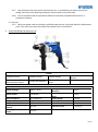
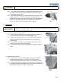
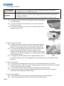
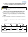
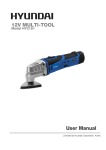
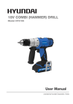
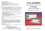
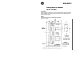
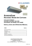
230V 710W IMPACT DRILL
Model HY2158
User Manual
CONTENTS
Section Description
1. OWNER’S MANUAL & SAFETY INSTRUCTIONS
2. GENERAL SAFETY
3. QUICK REFERNCE GUIDE
Page No/No’s
3
3–5
5
4. UNPACKING AND ASSEMBLY
6–7
5. OPERATION
7–9
6. GENERAL MAINTENANCE
9
7. SYMBOLS
9
8. ENVIRONMENTAL
10
9. GENPOWER CONTACT DETAILS
10
10. DECLARATIONS OF CONFORMITY
10
Page 2
1. OWNER’S MANUAL & SAFETY INSTRUCTIONS
1.1. How to read the manual.
1.1.1. Keep this manual for the safety warnings and precautions, assembly, operation, inspection,
maintenance and cleaning procedures.
1.1.2. Write the product’s serial number in the back of the manual near the assembly diagram (or
month and year of purchase if product has no number).
1.1.3. Keep this manual and the receipt in a safe and dry place for future reference.
1.1.4. The term “power tool” in the warnings refers to your mains operated (corded) power tool or
battery-operated (cordless) power tool.
1.1.5. This combi drill is intended for inserting and removing screws and bolts within the drill’s
capability.
2. GENERAL SAFETY
Non-observance
will result in the
risk of serious
injury or death to
oneself or others.
Non- observance
will result in the
risk of injury to
oneself or others.
Indicates a hazard
which, if not
avoided, might
result in minor or
moderate injury.
NOTE or
IMPORTANT These
give details or
further
information on
what has already
been said, and aim
to prevent damage
to the machine or
cause other
damage.
Read Manual
DO NOT let comfort or familiarity with product (gained from repeated use) replace
strict adherence to safety rules for the subject product.
MISUSE or failure to follow the safety rules stated in this instruction manual may
cause serious personal injury.
2.1. Work Area Safety
2.1.1. Keep work area clean and well lit. Cluttered or dark areas invite accidents.
2.1.2. Do not operate power tools in explosive atmospheres, such as in the presence of flammable
liquids, gases or dust. Power tools create sparks which may ignite the dust or fumes.
2.1.3. Keep children and bystanders away while operating a power tool. Distractions can cause you
to lose control.
2.2. Electrical Safety.
2.2.1. Power tool plugs must match the outlet. Never modify the plug in any way. Do not use any
adapter plugs with earthed (grounded) power tools. Unmodified plugs and matching outlets
will reduce risk of electric shock.
2.2.2. Avoid body contact with earthed or grounded surfaces, such as pipes, radiators, ranges and
refrigerators. There is an increased risk of electric shock if your body is earthed or grounded.
2.2.3.
Page 3
2.2.4. Do not expose power tools to rain or wet conditions. Water entering a power tool will
increase the risk of electric shock.
2.2.5. Do not abuse the cord. Never use the cord for carrying, pulling or unplugging the power
tool. Keep cord away from heat, oil, sharp edges and moving parts. Damaged or entangled
cords increase the risk of electric shock.
2.2.6. When operating a power tool outdoors, use an extension cord suitable for outdoor use.
2.2.7. Use of a cord suitable for outdoor use reduces the risk of electric shock.
2.2.8. If operating a power tool in a damp location is unavoidable, use a residual current device
(RCD) protected supply. Use of an RCD reduces the risk of electric shock.
2.3. Personal Safety.
2.3.1. Stay alert, watch what you are doing and use common sense when operating a power tool.
Do not use a power tool while you are tired or under the influence of drugs, alcohol or
medication. A moment of inattention while operating power tools may result in serious
personal injury.
2.3.2. Use personal protective equipment. Always wear eye protection. Protective equipment such
as dust mask, non-skid safety shoes, hard hat, or hearing protection used for appropriate
conditions will reduce personal injuries.
2.3.3. Prevent unintentional starting. Ensure the switch is in the off-position before connecting to
power source and/or battery pack, picking up or carrying the tool. Carrying power tools with
your finger on the switch or energizing power tools that have the switch on invites accidents.
2.3.4. Remove any adjusting key or wrench before turning the power tool on. A wrench or a key
left attached to a rotating part of the power tool may result in personal injury.
2.3.5. Do not overreach. Keep proper footing and balance at all times. This enables better control
of the power tool in unexpected situations.
2.3.6. Dress properly. Do not wear loose clothing or jewellery. Keep your hair, clothing and gloves
away from moving parts. Loose clothes, jewellery or long hair can be caught in moving parts.
2.3.7. If devices are provided for the connection of dust extraction and collection facilities, ensure
these are connected and properly used. Use of dust collection can reduce dust-related
hazards.
2.4. Power Tool Use and Care.
2.4.1. Do not force the power tool. Use the correct power tool for your application. The correct
power tool will do the job better and safer at the rate for which it was designed.
2.4.2. Do not use the power tool if the switch does not turn it on and off. Any power tool that
cannot be controlled with the switch is dangerous and must be repaired.
2.4.3. Disconnect the plug from the power source and/or the battery pack from the power tool
before making any adjustments, changing accessories, or storing power tools. Such preventive
safety measures reduce the risk of starting the power tool accidentally.
2.4.4. Store idle power tools out of the reach of children and do not allow persons unfamiliar with
the power tool or these instructions to operate the power tool. Power tools are dangerous in
the hands of untrained users.
2.4.5. Maintain power tools. Check for misalignment or binding of moving parts, breakage of parts
and any other condition that may affect the power tool’s operation. If damaged, have the
power tool repaired before use. Many accidents are caused by poorly maintained power tools.
2.4.6. Keep cutting tools sharp and clean. Properly maintained cutting tools with sharp cutting
edges are less likely to bind and are easier to control.
Page 4
2.4.7. Use the power tool, accessories and tool bits etc. in accordance with these instructions,
taking into account the working conditions and the work to be performed.
2.4.8. Use of the power tool for operations different from those intended could result in a
hazardous situation.
2.5. Service.
2.5.1. Have your power tool serviced by a qualified repair person using only identical replacement
parts. This will ensure that the safety of the power tool is maintained.
3. QUICK REFERENCE GUIDE and USE
PARTS
1 Keyless Chuck.
2 Mode Selector.
3 Depth Gauge.
5 Variable Speed Thumb
Wheel/Power Switch.
6 Power ON Indicator.
7 Forward/Reverse
Lever.
4 Power Switch Lock
Button.
8 Auxiliary Side Handle
TECHNICAL SPECIFICATION
Rated Voltage.
230V – 50 Hz.
Rated Power.
710 Watts.
No Load Speed.
Impact Rate.
Keyless Chuck Size.
Drilling Capacity into
Wood.
Drilling Capacity into
Steel.
0 - 2,800/min.
0 – 4,800 bpm.
13 mm.
Drilling Capacity into
Masonry.
Net Weight (Machine
Only).
Cable Length.
Sound Pressure Level.
Sound Power Level.
30 mm.
Vibration Level
16 mm.
2.45 Kg
2 metres
88 dB (LpA)
99 dB (LwA)
3.579 m/s2
13 mm.
Page 5
4. UNPACKING and ASSEMBLY
This packaging contains sharp objects. Take care when unpacking. Remove the
machine, together with the accessories supplied, from the packaging.
4.1. Unpacking.
4.1.1. Check carefully to ensure that the machine is in good condition and account for all the
accessories listed in this manual.
4.1.2. If any parts are found to be missing, the machine and its accessories should be returned
together in their original packaging to the retailer.
4.2. Assembly
Before carrying out any assembly or disassembly of the unit please ensure that the
unit is not connected to the electrical supply.
4.2.1. Do not throw the packaging away, keep it safe throughout the guarantee period, then
recycle if possible, otherwise dispose of it by the proper means.
4.2.2. Do not let children play with empty plastic bags due to the risk of suffocation.
4.3. Fitting the Auxiliary Side Handle
Be sure the auxiliary handle is securely tightened against the depth gauge clamp.
This secures the depth gauge at the desired depth of drilling and also secures the
auxiliary handle.
4.3.1. The Auxiliary side handle is attached to the front collar of the drill. Loosen
the handle assembly by turning the handle clockwise, Fig 1, and slide the
auxiliary side handle over the keyless chuck onto the front collar of the drill.
4.3.2. Securely tighten by turning the auxiliary handle counter clockwise.
4.4. Fitting The Depth Gauge
4.4.1. The drill is supplied with a depth gauge used for drilling holes to
a required depth. Loosen the auxiliary side handle Fig 1, and
insert the depth gauge into the hole on the side of the auxiliary
handle, Fig 2.
4.4.2. Measure back from the drill tip and move the depth gauge back
to the required measured depth. Securely tighten by turning the
auxiliary handle counter clockwise. The end of the depth gauge
will come into contact with the work surface when the required
depth of hole is reached.
4.5. Installing drill bits.
Page 6
Always disconnect the machine from the power supply before adjustment,
changing accessories and maintenance.
4.5.1. The keyless chuck fitted to this impact drill allows for the easy
installation and removal of bits and drills. The chuck has two
rotating grips, Fig 3 (1 & 2).
4.5.2. Select the drill /driver bit required and insert it into the chuck
jaws, turn grip 1 in a clockwise direction until jaws grip the
drill/driver bit. With your free hand hold grip 2 firmly and rotate
grip 1 in a clockwise direction until it tightens onto the drill
/driver bit. Do not use unnecessary force to tighten.
5. OPERATION
Before connecting the impact drill to a power supply, make sure it is not in the
‘locked on’ position. Failure to do so could result in accidental starting of the drill
resulting in possible serious injury.
5.1. Switching impact drill ON and OFF.
5.1.1. This machine is fitted with a continuous operation button. To
start the machine squeezes the On/Off trigger, Fig 4.
5.1.2. When the machine starts press in the continuous operation
button located on the side of the handle, Fig 5, release the
On/Off trigger.
5.1.3. The machine will now run continuously without the need to
maintain pressure on the On/Off trigger.
5.1.4. To stop the machine briefly squeeze then release the On/Off
trigger.
5.2. Variable Speed Control.
5.2.1. Light pressure on the On/Off trigger results in low speed,
allowing drilling to begin in a smooth, controlled manner.
Further pressure on the switch results in an increase in speed.
5.2.2. The desired speed can be pre-selected with the thumb wheel,
Fig 6 (also possible during operation). The rotational speed to be
used depends upon the material being drilled.
Page 7
5.3. Changing the Rotation.
The impact drill is not designed for reverse hammering. Failure to heed this
warning may result in damage to the drill.
The design of the switch will not permit changing the direction of rotation while
the drill is running. Release the On/Off trigger and allow the drill to stop before
changing its direction.
The impact drill will not run unless the lever is pushed fully to the left or right.
5.3.1. The direction of the chuck is controlled by a lever located above
the On/Off trigger.
5.3.2. For forward rotation move the lever to the left marked with a
forwards arrow, Fig 7.
5.3.3. For reverse rotation move the lever to the right marked with a
backwards arrow, Fig 8.
5.4. Adjusting the drill mode.
5.4.1. Locate the selector switch on the top of the drill housing, Fig 9.
Simply push the selector switch to the left hand side of the drill
(with the chuck facing forward) to select hammer drilling mode.
5.4.2. To select normal drilling mode push the selector switch to the
right hand side of the drill (with the chuck facing forward).
Tungsten carbide drill bits are required for drilling concrete, stone
and masonry. The best drilling progress is achieved using tungsten
carbide tipped drill bits.
5.4.3. Only High Speed Steel (HSS) drill bits in good condition should
be used for drilling metal or wood. Spade bits and brad point bits are only used for drilling
wood etc.
5.5. Tip for Drilling Tiles.
5.5.1. Place a piece of masking tape onto the tile in the approximate position for the hole.
5.5.2. Mark the position of the hole onto the masking tape this will prevent the drill from skidding
across the tile when the drill is started.
5.5.3. Set the selector switch to the drill symbol and slowly drill through the tile.
5.5.4. When the tile has been full drilled through change the selector switch to the hammer
symbol and continuing with hammer drilling.
5.6. Tip for Drilling Metal.
5.6.1. When drilling metal, use a light oil on the drill bit to keep it from overheating.
5.6.2. The oil will prolong the life of the bit and increase the drilling action.
Page 8
5.7. Work piece Clamping.
5.7.1. To prevent the work piece from spinning (if drill bit becomes jammed), it is recommended
that a drill vice or other suitable clamp is used to secure the work piece during the drilling
operation.
6. GENERAL MAINTENANCE
Do not at any time let brake fluids, petrol, petroleum based products, penetrating
oils, etc., come in contact with plastic parts.
Chemicals can damage, weaken or destroy plastic which may result in serious
personal injury.
6.1. Avoid using solvents when cleaning plastic parts. Most plastics are susceptible to damage from
various types of commercial solvents and may be damaged by their use. Use clean cloths to
remove dirt, dust, oil, grease, etc.
6.2. Electric tools used on fiberglass material, wallboard, compounds, or plaster are subject to
accelerated wear and possible premature failure because the fiberglass chips and grindings are
highly abrasive to bearings, brushes, commentators, etc.
6.3. Consequently, we do not recommended using this tool for extended work on these types of
materials.
6.4. However, if you do work with any of these materials, it is extremely important to clean the tool
using compressed air.
6.5. Lubrication
6.5.1. All of the bearings in this tool are lubricated with a sufficient amount of high grade lubricant
for the life of the unit under normal operating conditions. Therefore, no further lubrication is
required.
7. SYMBOLS
7.1. The rating plate on this product may show some or all of the following symbols.
7.2. These represent important information about the product or instructions on its use.
Wear hearing protection.
Wear eye protection.
Wear respiratory protection.
Product conforms to RoHs
requirements
Conforms to relevant safety
standards.
General warning
Double insulated for
additional protection.
Read the instruction manual.
Waste electrical products should not be disposed of with
household waste.
Please recycle where facilities exist.
Check with your Local Authority or retailer for recycling
advice.
Page 9
8. ENVIRONMENTAL
8.1. Do not dispose of electric equipment together with household waste material! In observance of
European Directive 2012/19/EC on waste electrical and electronic equipment and its
implementation in accordance with national law, electric equipment that have reached the end of
their life must be collected separately and returned to an environmentally compatible recycling
facility. If electrical appliances are disposed of in landfills or dumps hazardous substances can leak
into the groundwater and get into the food chain, damaging your health and well-being.
8.2. For further information on the disposal of this product, please contact your dealer or your nearest
domestic waste collection service.
8.3.
Reduce – Reuse - Recycle unwanted materials instead of disposing of them as waste. All
tools, accessories and packaging should be sorted, taken to a recycling centre and disposed of in a
manner which is compatible with the environment.
8.4.
When the product is no longer required, it must be disposed of in a manner which is
compatible with the environment.
9. GENPOWER CONTACT DETAILS
9.1. Postal address;
Genpower Limited, Isaac Way, Pembroke Dock,
Pembrokeshire, SA72 4RW, UK.
9.2. Telephone contact number;
Office
+44 (0) 1646 687880
9.3. Email contact;
Technical
[email protected]
9.4. Web site;
www.hyundaipowerequipment.co.uk
10. DECLARATIONS OF CONFORMITY
10.1.
Genpower Ltd confirms that this Hyundai product conform to the following CE Directives;
10.1.1. 2006/42/EC Machinery Directive
10.1.2. 2004/108/EC EMC Directive
10.1.3. 2006/95/EC Low Voltage Directive
Page 10
Page 11
Page 12