1
1/18 Xcelorin™ Sensored Rock Crawling ESC
Thank you for purchasing the Xcelorin Sensored Rock Crawling Electronic Speed
Control (ESC). This ESC will provide you the benefit of the latest in brushless
technology. Featuring an advanced software interface with which you can
finely tune the feel of the ESC to your needs, or use the Quick Programming
Card (QPC) to make adjustments.
We believe it will be to your benefit to take the time and effort to read this
manual.
We are confident you will be satisfied with the performance of the Xcelorin
Sensored Rock Crawling ESC.
Horizon Customer Support
If you have any questions concerning setup or operation of your Xcelorin ESC,
please call Horizon customer support at 1-877-504-0233, Horizon Hobby UK at
+44 (0) 1279 641 097 or Horizon Hobby Deutschland at +49 4121 46199 66.
You are welcome to call us with any support issue or question you may have.
LOSB9501 Xcelorin Electronic Speed Control v1.0
Page 1
Table of Contents
Overview ........................................................................................... 3
Profile Overview ................................................................................. 5
Initial Profile Setting from the Factory ................................................... 6
Overriding the Active Profile ................................................................. 7
Selecting profiles ................................................................................ 8
Modifying the ACTIVE Profile ................................................................ 9
Using the Quick Programming Card....................................................... 10
Setup/Calibration to Transmitter........................................................... 12
Confirmation of Full Throttle and Brake ................................................. 14
Connect the Xcelorin ESC and Sensored Motor ....................................... 15
Connecting the Xcelorin ESC to your Receiver ........................................ 16
Xcelorin Software Installation ............................................................... 17
Xcelorin Software Overview ................................................................. 28
Updating ESC Firmware ....................................................................... 31
Xcelorin Sensored Brushless ESC Specifications ...................................... 37
Xcelorin Replacement Parts .................................................................. 38
Warranty Period ................................................................................. 39
Declaration of Conformity .................................................................... 47
LOSB9501 Xcelorin Electronic Speed Control v1.0
Page 2
Overview
The Xcelorin Sensored Rock Crawling ESC is specifically designed for operating
sensored brushless motors. Featuring low on-resistance, enhanced throttle
response and strong brakes, this ESC has enough features to satisfy the most
demanding driver. The preinstalled high-airflow fan attached to the ESC heat
sink keeps it cool and performing to the peak of its ability. In order to maintain
25A continuous current draw, the Xcelorin ESC uses very high-quality
electronics and the best MOSFET transistors available.
LOSB9501 Xcelorin Electronic Speed Control v1.0
Page 3
A key feature is the three (3) stored settings within the ESC that are easily
recalled for convenient use. These stored settings are referred to as “profiles.”
These do not limit the functions of the ESC as you can easily use the included
Quick Programming Card (QPC) to make changes to any desired setting.
The Low Voltage Cutoff (LVC) is preset for a 3S 11.1V Lithium Polymer (LiPo)
battery. It can be changed to support 2S LiPo and NiMH batteries. Using the
Quick Programming Card (QPC), adjustments to the ESC can be made quickly
and simply.
The Xcelorin Rock Crawler ESC has no delay between forward and reverse to
allow you to catch yourself if you get into trouble on the rocks. At higher wheel
speeds this can place an incredible strain on your drivetrain. Be sure your
equipment can handle these loads before going from forward to reverse
instantly at higher wheel speeds. It is not recommended to repeatedly go from
full forward to reverse as this creates large currents that can eventually lead to
damage of the ESC.
LOSB9501 Xcelorin Electronic Speed Control v1.0
Page 4
Profile Overview
These stored settings, also referred to as “profiles,” are defined as follows:
Profile #1 (Default) – “3S Worm Drive”
Cutoff Voltage – Li-ion/LiPo 3 Cells/9.0V
Throttle Limit - 0% (No limit)
Reverse Throttle Limit - 100% (No limit)
Initial Acceleration - High
Percent Drag Brake - 0%
Legacy or 2.4GHz - 2.4GHz
Reverse Rotation – Off
Profile #2 - “2S Worm Drive”
Cutoff Voltage – Li-ion/LiPo 2 Cells/6.0V
Throttle Limit - 0% (No limit)
Reverse Throttle Limit - 100% (No limit)
Initial Acceleration - High
Percent Drag Brake - 0%
Legacy or 2.4GHz - 2.4GHz
Reverse Rotation - Off
LOSB9501 Xcelorin Electronic Speed Control v1.0
Page 5
Profile #3 - “2S Non-Worm Drive”
Cutoff Voltage – Li-ion/LiPo 2 Cells/6.0V
Throttle Limit - 0% (No limit)
Reverse Throttle Limit - 100% (No limit)
Initial Acceleration - High
Percent Drag Brake - 100%
Legacy or 2.4GHz - 2.4GHz
Reverse Rotation - On
NOTE: You may also use the supplied Xcelorin Setup Software to access these
features of the ESC.
Initial Profile Setting from the Factory
Cutoff Voltage – Li-ion/LiPo 3 Cells/9.0V
Throttle Limit - 0% (No limit)
Reverse Throttle Limit - 100% (No limit)
Initial Acceleration - High
Percent Drag Brake - 0%
Legacy or 2.4GHz - 2.4GHz
Reverse Rotation – Off
LOSB9501 Xcelorin Electronic Speed Control v1.0
Page 6
Overriding the Active Profile
There are three (3) saved profiles within the ESC that were previously
described. To override a setting within the active profile, select a saved profile
that resembles your needs, or make further changes to the current profile.
Review the QPC and set the jumpers to your choice. You must make a choice
for each area of the QPC (Cutoff Voltage, Initial Acceleration, Throttle Limit,
Reverse Throttle Limit, Drag Brake, Frequency and Reverse Rotation).
For example if you have the ESC active profile set to Profile #1 (Default) and
would like Mid Initial Acceleration (from High) but would like nothing else
changed, place the jumpers on the following choices.
Cutoff Voltage – 3S LiPo
Throttle Limit – 0% (No limit)
Reverse Throttle Limit – 100% (No limit)
Initial Acceleration – Mid
Percent Drag Brake – 0%
Legacy or 2.4GHz – 2.4GHz
Reverse Rotation – Off
Then follow the instructions for using the Quick Programming Card. You can
change one setting at a time or any combination. Making the above change is
ONLY overriding the active profile. At any time, you can reset the ESC to
Profile #1 and the active profile is returned to the original Profile #1 settings.
LOSB9501 Xcelorin Electronic Speed Control v1.0
Page 7
Selecting profiles
Notice that Profile #1 is set from the factory as the DEFAULT.
1. Turn the Transmitter on.
2. Turn the vehicle on.
3. With the ESC turned on and ready for operation, press and hold the setup
button until both the Yellow and Blue LEDs flash.
4. Release setup button.
5. The status LEDs flash to indicate the current profile setting.
LED status for each Profile below:
Profile 1 Yellow and Blue LEDs flash (default setting)
Profile 2 Yellow, Blue and Green LEDs flash
Profile 3 Yellow, Blue, Green and Red Flash
6. To make a change, quickly press the setup button, which will advance you to
the next profile.9
7. When you are finished, press and hold the setup button for 2 seconds, the
four status LEDs will scroll and the new selection will be stored to the active
memory of the ESC.
LOSB9501 Xcelorin Electronic Speed Control v1.0
Page 8
8. If you do not press the setup button within 15 seconds, the four status LEDs
will scroll to indicate you are exiting programming. The ESC will return to
neutral and be ready for use without any change.
Modifying the ACTIVE Profile
The Xcelorin Quick Programming Card (QPC) is used to make all adjustments to
the active profile in your ESC. Any ACTIVE profile can be modified.
LOSB9501 Xcelorin Electronic Speed Control v1.0
Page 9
Using the QPC, you can set the following:
Cutoff Voltage
Throttle Limit
• NiMH
• 2S LiPo
• 3S LiPo
• No Limit (0%)
• 80% Full Throttle
• 60% Full Throttle
Initial Acceleration
Reverse Throttle Limit
• Low
• Mid
• High
• No Limit (0%)
• 80% Full Throttle
• 60% Full Throttle
Drag Brake
Frequency
•
•
•
•
• Legacy (AM/FM crystal radios)
• 2.4GHz (DSM)
0% (Worm Gear)
60%
80%
100%
Reverse Rotation
• Off
• On
Using the Quick Programming Card
With the QPC in your hand and the back facing you, notice the small jumper
connectors. The jumpers are used to indicate which function you want to
activate.
LOSB9501 Xcelorin Electronic Speed Control v1.0
Page 10
To change the settings rearrange the small jumpers to the
desired settings.
To upload to the ESC do the following:
1. Ensure the transmitter and vehicle are turned off.
2. Make sure a battery pack is installed that has some
charge in it.
3. Connect the battery to the vehicle.
4. Turn the power on to the ESC, wait for the Blue (or
Blue/Yellow) LED to come on.
5. Disconnect the Signal wire for the ESC from the receiver.
6. Connect the Signal wire to the top of the QPC, ensure it is connected
correctly.
7. Pay close attention to the ESC LEDs. You will notice the Red LED flash, and
on the QPC the Red LED will come on. If you do not notice the ESC Red LED
flash, you can unplug the Signal wire from the QPC and reconnect to verify the
operation of the Red LEDs. Once you see the ESC flash Red and the QPC turn
on Red, the ESC has accepted the programming.
8. Disconnect the Signal wire from the QPC, turn off the power switch.
9. Reconnect the signal wire into the receiver.
10. The ESC has been updated and you are ready.
LOSB9501 Xcelorin Electronic Speed Control v1.0
Page 11
Note: If you should happen to lose any of your jumpers they are the
same jumpers used with computers and easily obtained at a computer
store.
ESC Warning LEDs
• If the Battery low voltage cutoff (LVC) is reached, the Red LED will blink.
• The Red LED will automatically stop blinking should the battery voltage
recover above the chosen Low Voltage Cutoff.
• If the ESC has detected a thermal overload, the Yellow LED will blink. Let the
ESC cool down.
Setup/Calibration to Transmitter
To perform the setup/calibration between the ESC and Transmitter follow these
steps:
1. Turn on the transmitter.
2. While turning on the vehicle Press and Hold the setup button, notice the
Yellow LED is now ON solid. When the Yellow LED is on solid, you can release
the setup button.
LOSB9501 Xcelorin Electronic Speed Control v1.0
Page 12
Note: If you cannot get the ESC to Calibrate, you may need to reverse your
Throttle Servo on the transmitter.
3. Using the throttle trigger pull Full Throttle until the Green LED is ON solid.
4. Next push the throttle trigger to Full Brake until the Red LED is ON solid.
5. Now return the throttle trigger to the Neutral position and the Blue LED is
ON solid.
6. Turn off the vehicle/ESC power switch.
7. Turn the vehicle/ESC back ON; you are now ready to use the ESC.
Normal Operation
• After turning on the vehicle, the Blue LED will be on for normal operation.
• If reverse is active then you will notice the Yellow LED is also on.
LOSB9501 Xcelorin Electronic Speed Control v1.0
Page 13
Confirmation of Full Throttle and Brake
• While the ESC is on and operational, if you pull the throttle trigger to Full
Throttle the Green LED will turn ON solid.
• Push the throttle trigger to Full Brake, the red LED will turn ON solid.
Note: If the transmitter’s brake endpoint adjustment is reduced after
calibration then the Red LED will not turn on.
LOSB9501 Xcelorin Electronic Speed Control v1.0
Page 14
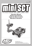
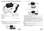
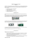
Connect the Xcelorin ESC and Sensored Motor
There are three wires from the ESC a Blue, Yellow and Orange, which are to be
connected to the motor.
Below see an Xcelorin Sensored Brushless motor, each wire should be
connected to a single motor lead. The order of connection is important and
when you are looking at the motor with the tabs up, the wires attach from left
to right in the following sequence: Blue on far left, Yellow to the center tab, and
Orange on the far right. Make certain there is not a short across any of the
motor connections. If shorted together, you will damage the ESC when the
batteries are connected.
-
If the motor you are using runs backwards after installation, you can correct this
using the software program and selecting the Reverse Rotation feature.
LOSB9501 Xcelorin Electronic Speed Control v1.0
Page 15
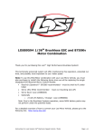
Connecting the Xcelorin ESC to your Receiver
The Receiver wire will connect to nearly all current receivers. Plug it into the
Throttle Channel of the receiver.
Brown
Negative
Red
Positive
Orange Signal
LOSB9501 Xcelorin Electronic Speed Control v1.0
Page 16
Xcelorin Software Installation
In the box along with your Electronic Speed Control, you will find:
•
•
•
Xcelorin Software CD
USB Cable
USB Adapter
Requirements:
•
•
•
Windows Operating System preferably Windows XP or higher
USB Port to be available compatible with USB 1.0 or higher
You must have FULL Administrator rights on your computer to install
Before installing the Losi Xcelorin Setup Software, ensure there is no
prior version(s) installed using the ADD/REMOVE Programs function
found in your CONTROL PANEL. Check to make sure you are installing
the latest version of the software by visiting www.xcelorin.com.
To install the Xcelorin software make sure you have FULL Administrator rights
on the machine you want to install to. If not, the install will complete but will
not connect with the USB Adapter.
LOSB9501 Xcelorin Electronic Speed Control v1.0
Page 17
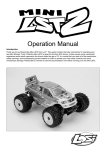
1. Now, insert the CD into your CD/DVD Player.
The following should automatically display.
LOSB9501 Xcelorin Electronic Speed Control v1.0
Page 18
2. When ready select the Next button. If you wish to cancel, select the Cancel
button.
If you do not get the previous panel, click on My Computer and then select
(click on) the CD/DVD Drive to open it.
You should then have a panel similar to the one below.
Select and click on the Losi_Setup_1029.exe program icon. (You will now see
the panel expected in Step 1 above.)
LOSB9501 Xcelorin Electronic Speed Control v1.0
Page 19
3. The following should now be presented. You can change the default
directory if desired, we recommend using this default.
When ready, select the Next button. If you wish to cancel, select the Cancel
button.
LOSB9501 Xcelorin Electronic Speed Control v1.0
Page 20
4. The following should now be displayed and asking you where you would like
a shortcut saved to.
When ready, select the Next button. If you wish to cancel, select the Cancel
button.
LOSB9501 Xcelorin Electronic Speed Control v1.0
Page 21
5. The following should now be displayed asking you if you would like to save
an additional shortcut to the Desktop. If you do not wish to add a shortcut on
the Desktop deselect the button next to ‘Create a Desktop icon’.
When ready, select the Start button. If you wish to cancel, select the Cancel
button.
LOSB9501 Xcelorin Electronic Speed Control v1.0
Page 22
6. The following should now be displayed confirming the install location.
When ready, select the Install button. If you wish to make any changes, select
the Back button to go back to the appropriate window. If you wish to cancel,
select the Cancel button.
LOSB9501 Xcelorin Electronic Speed Control v1.0
Page 23
7. The following should now be displayed confirming that install has succeeded.
Click Finish to complete the installation and close the window.
LOSB9501 Xcelorin Electronic Speed Control v1.0
Page 24
8. Connect the USB cable to your Windows PC or Laptop computer.
9. Connect the Xcelorin USB Adapter to the mini USB connector on the USB
Cable.
You will be prompted to install the device drivers. They are both unsigned so
select OK and continue. After a few moments, the USB adapter LED will turn
from Red to Green.
If your Adapter LED remains Red, then disconnect the Adapter, wait a minute
and then reconnect. If the Green LED does not come on, please reboot before
calling Horizon support at 1 877-504-0233, Horizon Hobby UK at +44 (0) 1279
641 097 or Horizon Hobby Deutschland at +49 4121 46199 66.
Note: If you have Windows 2000, you will be required to reboot before the
USB Adaptor will connect and the small LED on the adapter turns from Red to
Green.
LOSB9501 Xcelorin Electronic Speed Control v1.0
Page 25
10. With the Xcelorin USB Adapter LED now green, you are ready to start the
Xcelorin Software. Locate and select the Losi icon on your desktop.
Notice in the Connection box the USB is Green and the ESC is still Red.
11. You are ready to connect the Adapter to the ESC, using the Signal Wire.
WARNING:
Disconnect the battery from the ESC before connecting the Xcelorin USB
adapter to the speed control.
Failure to do so may result in DAMAGE TO YOUR COMPUTER
LOSB9501 Xcelorin Electronic Speed Control v1.0
Page 26
Please note the label on the USB Adapter, there are 3 color bars each marked
and indicating how to connect the Receiver wire to the adapter.
12. With the ESC connected to the USB Adapter, the Xcelorin Software
Connection status icons should now both be GREEN.
The Losi Xcelorin software is now installed and ready for use.
LOSB9501 Xcelorin Electronic Speed Control v1.0
Page 27
Xcelorin Software Overview
Using this you will find it quite easy to configure your new speed control. On the main
panel, you will notice this button
, if you click on this, the specific help for that function
will display.
Take a moment to review the selectable functions, and read the specific help text for each
to become familiar with them. To make configuration changes to a function select the
setting you want, and from the drop-down menu select your new choice or option. When
you are satisfied and finished with this configuration, click the “SEND Settings” button
located on the bottom (off center) of each tabbed page.
Note the four tabs down the right-hand side, General, Throttle, Brake, and About.
LOSB9501 Xcelorin Electronic Speed Control v1.0
Page 28
General Tab: Here you will find the following configuration settings:
Battery Type and Cutoff Voltage, Brake/Reverse, Motor Timing, Initial Acceleration, Percent
Drag Brake, ESC operating mode, Deadband adjustment, Braking Percentage, Throttle
Limit, Reverse Throttle Limit and Motor Rotation. All changes are done at your own risk.
Throttle Tab: This tab is disabled for crawler use.
Brake Tab: This tab is disabled for crawler use.
About Tab: Here you will see the Setup software version installed, and date of last
update. This will be helpful information should you have questions or support concerns.
Connection: This section is displayed on every Tab. There are two icons; one for the USB
connection, the other indicates the Electronic Speed Control connection. They are RED in
color when disconnected and GREEN on connection.
Note: Without an understanding of a specific function and reason, it is not recommended
that you make changes to the “default” configuration. There have been defaults selected
as a direct result of our testing. Changing of the configuration will be at your own risk.
Read Settings: Use of this button will read the current Electronic Speed Control (ESC)
configuration and present it on the current tabbed page only.
Send Setting: Use of this button will send (write) the current selected configuration to
the ESC for the current tabbed page only.
Upgrade Firmware: Use of this button will begin the firmware upgrade process. The
following pop-up will be displayed, and you need to select the location of the firmware
update file. You may cancel this process here without any effect to the ESC firmware.
LOSB9501 Xcelorin Electronic Speed Control v1.0
Page 29
Click on the file that you want to use for the update. CAUTION: Be sure that this is the
correct file. Updating the ESC with an incorrect firmware file may corrupt the ESC and
make it inoperable. Click on Open once you have selected the appropriate file. The update
process will begin automatically. The progress status percentage of the upgrade will be
displayed in the lower right. Please do not unplug your computer or the ESC or close the
program while the upgrade is in progress or damage to the ESC may result. It is highly
recommended that if updating the firmware with a laptop to make sure that it is plugged
into a wall outlet during the update process.
If no problems were encountered, OK will be displayed and the configuration redisplayed.
You are finished with the upgrade and you can re-configure the ESC or end the program.
If a problem is encountered and the upgrade fails, simply restart the upgrade process
again. If there should be another failed upgrade, then end all other programs on your
computer and possibly re-download the file from the Losi website.
LOSB9501 Xcelorin Electronic Speed Control v1.0
Page 30
If the problem persists, then please call us at Losi/Horizon Product Support – 1 877 504
0233, Horizon Hobby UK at +44 (0) 1279 641 097 or Horizon Hobby Deutschland at +49
4121 46199 66.
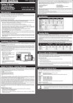
Updating ESC Firmware
Description: By supporting the ability to upgrade your firmware, the Xcelorin ESC will
provide you with the benefits of future enhancements or quickly allow you to realize a
software fix. Within a short period, you can upgrade your ESC firmware rather than
packaging your ESC and sending it in for upgrade or repair. When you update the
software, you are literally getting a new and improved ESC.
We have the ability to offer NEW configuration parameters, introduce finer adjustments
and many more items with this capability.
Current Software: grayed out, shows the software currently on the controller.
Xcelorin ESC Model
A0101XX.LSC
B0101XX.LSC
C0101XX.LSC
D0101XX.LSC
-
is indicated by the first character in the Software Level.
18th Xcelorin Sensored Crawler
Reserved
18th Xcelorin Sensorless
10th Xcelorin Sensored
E0101XX.LSC
- 10th Xcelorin Sensorless
F0101XX.LSC
- 8th Xcelorin Sensorless
G0101XX.LSC
- 10th Xcelorin Sensored Crawler
H0101XX.LSC
- Reserved
Note: XX denotes the incremental release level
LOSB9501 Xcelorin Electronic Speed Control v1.0
Page 31
General TAB Information
Battery Type –Select NiMH, or Lithium-Ion/Lithium Polymer batteries
Cutoff Voltage – This is a critical option to understand and used to protect Lithium or M1
batteries from being over-discharged which will shorten the life, cause damage to the
battery, or even result in Fire or Personal Injury.
When using NiMH batteries you do not need to set a cutoff voltage to protect the
batteries. NiMH batteries typically stop operating your vehicle before any damage occurs.
If you are using more than 6-cell NiMH batteries, you must adjust the cutoff voltage, for
example if you are using an 8-cell pack of NiMH batteries you would use a cutoff of 5.6V (8
x 0.7V = 5.6V). If you are using fewer cells of NiMH batteries, a cutoff voltage of 4.0V will
provide power for your radio system to operate and reduce the chance of losing control.
•
No Cutoff
The choice for racing used along with quality NiMH battery packs.
•
Customize Voltage Cutoff (for NiMH Batteries) you can select a starting cutoff
voltage of 4, 5, 6, 9 or 12 volts. Then using the up/down to the right of the voltage
you can increase the voltage stepping up 0.1V between the selectable settings.
Following the above example for an 8-cell NiMH battery, you would select 5.0V and
then increase 6 steps up to 5.6V.
DO NOT USE the above setting with any type of Lithium battery pack
LOSB9501 Xcelorin Electronic Speed Control v1.0
Page 32
When using any Lithium or M1 (A123) batteries, they must not be discharged to less
than 3.0V per cell.
•
No Cutoff
The choice is not available and NOT recommended when using any
type of Lithium battery.
•
Customize Voltage Cutoff (for Lithium Batteries) after selecting the number of cells
(2 or 3) the default voltage is displayed. For example, you select a 2S or 2-cell
battery; the default cutoff voltage will be 6.0V. You may raise this to protect your
expensive batteries in 0.1V increments up to 7.0V. For 3S or 3-cell, the default cutoff
is 9.0V and you may increase this up to 10.5V.
Brake/Reverse – This defaults to Forward with Reverse for crawler use and
cannot be changed.
Throttle Limit – Use this to limit the power available using forward throttle.
The lower the percent the less forward throttle speed will be available.
(Default)
• 0%
100% of forward speed
•
50%
50% of forward speed
•
10%
90% of forward speed
•
60%
40% of forward speed
•
20%
80% of forward speed
•
70%
30% of forward speed
•
30%
70% of forward speed
•
80%
20% of forward speed
•
40%
60% of forward speed
•
90%
10% of forward speed
LOSB9501 Xcelorin Electronic Speed Control v1.0
Page 33
Reverse Throttle Limit - Use this to limit the power available using reverse
throttle. The lower the percent or level the less speed will be available in
reverse.
•
10%
10% of reverse speed
•
60%
60% of reverse speed
•
20%
20% of reverse speed
•
70%
70% of reverse speed
•
30%
30% of reverse speed
•
80%
80% of reverse speed
•
40%
40% of reverse speed
•
50%
50% of reverse speed
• 90%
(Default)
• 100%
90% of reverse speed
100% of reverse speed
Motor Timing - This option is disabled for crawler use.
Initial Acceleration - Use this to limit the initial power sent to the motor when
starting from a complete stop.
Using the LOW option, the vehicle will launch very slowly and provide the longest run
times. When using the HIGH choice, you will have wheel-spinning acceleration at the cost
of run time. This is also very tough on the batteries as the amperage draw can be very
high. If your vehicle cuts out, hesitates or loses radio control, you should consider setting
this at a lower value.
•
Low Using this option will provide longer run times and is easiest on the
batteries. It is a good choice for beginners.
LOSB9501 Xcelorin Electronic Speed Control v1.0
Page 34
•
•
Mid Medium requires more from your batteries, and is good for low traction
surfaces.
High This option will provide full acceleration and requires stout batteries to
supply the load required in this setting.
Braking Percent – This option is disabled for crawler use.
Percent Drag Brake – The drag brake function provides the driver a set
percentage of brake when you have the transmitter resting in neutral. This will
hold a vehicle without a worm gear drive system stationary when on an incline.
For a vehicle with a worm gear drive system there is sufficient drag within the
driveline to hold the vehicle on an incline. Use 0% drag brake to minimize the
load on the ESC and motor when stopped. This will lower temperatures and
increase run time. If your vehicle has a conventional drive system, then choose
the appropriate amount of brake for your application. Too much will increase
temperatures and lower run time.
•
Worm Gear (Default)
•
80%
•
50%
•
90%
•
60%
• 100%
•
70%
LOSB9501 Xcelorin Electronic Speed Control v1.0
Page 35
Legacy or 2.4GHz – This setting is intended to reflect what type of Radio
System you are using, i.e. Transmitter and Receiver.
Default is 2.4GHz. If you use a traditional radio, like a 27MHz, 40MHz or 75MHz system,
you can select the Legacy setting.
The Electronic Speed Control internal switching rate is increased with the 2.4GHz selection
and may cause interference with Legacy Radio Systems.
Neutral Deadband – This setting is disabled for crawler use.
Reverse Rotation – If your vehicle requires that the motor spin in the
opposite direction, set this setting to On.
For optimal performance, ensure the timing on your motor is set to 0 degrees advance. If
you cannot set the timing on your motor and it is not set to 0 degrees from the factory,
you may notice that the vehicle has more power in reverse and runs a bit hotter. This is
normal as the timing advance creates more power in the normal direction of rotation
(which would be reverse when this setting is set to On).
Throttle TAB information
Setting Throttle Profile – This feature is disabled for crawler use.
Brake TAB information
Setting Brake Profile – This feature is disabled for crawler use.
LOSB9501 Xcelorin Electronic Speed Control v1.0
Page 36
Xcelorin Sensored Brushless ESC Specifications
Type: Sensored Brushless ONLY
Cells w/BEC: 6-8 Cells (NiMH)/ 2S-3S (LiPo)
Auto Cutoff: Programmable
BEC Voltage: 5.0V, 2A
Forward: Y
Reverse: Y
Brake: Y
Continuous Maximum Current: 25A
Momentary Peak Current: 30A
Input Connector Types: Losi EC2 style
Motor Limit: 3.5T or higher 280-sized sensored brushless motors
Dimensions (WxLxH): 1.0 x 1.7 x 0.6 in (26.1 x 44.5 x 16.5 mm)
Weight: 1.1 oz (33 g)
LOSB9501 Xcelorin Electronic Speed Control v1.0
Page 37
Xcelorin Replacement Parts
LOSB9354
LOSB9362
Heat sink 18th ESC
$12.99
th
LOSB9379
Plastic Replacement case 18 with O-Ring
Quick Program Interface Card for
18th/10th Crawlers Only
$12.49
LOSB9386
Software CD USB Cable/Connector Replacement
$28.49
LOSB9369
Signal wire from ESC to Receiver
$3.99
LOSB9372
ESC On/Off Switch Harness
$9.99
LOSB9617
EC2 Device Connector, Male (2)
$3.99
LOSB9618
EC2 Battery Connector, Female (2)
$3.99
LOSB9501 Xcelorin Electronic Speed Control v1.0
$5.99
Page 38
Warranty Period
Exclusive Warranty- Horizon Hobby, Inc., (Horizon) warranties that the
Products purchased (the "Product") will be free from defects in materials and
workmanship at the date of purchase by the Purchaser.
Limited Warranty
Horizon reserves the right to change or modify this warranty
without notice and disclaims all other warranties, express or
implied.
(a) This warranty is limited to the original Purchaser ("Purchaser") and is not
transferable. REPAIR OR REPLACEMENT AS PROVIDED UNDER THIS WARRANTY
IS THE EXCLUSIVE REMEDY OF THE PURCHASER. This warranty covers only
those Products purchased from an authorized Horizon dealer. Third party
transactions are not covered by this warranty. Proof of purchase is required for
warranty claims. Further, Horizon reserves the right to change or modify this
warranty without notice and disclaims all other warranties, express or implied.
(b) Limitations- HORIZON MAKES NO WARRANTY OR REPRESENTATION,
EXPRESS OR IMPLIED, ABOUT NON-INFRINGEMENT, MERCHANTABILITY OR
FITNESS FOR A PARTICULAR PURPOSE OF THE PRODUCT. THE PURCHASER
LOSB9501 Xcelorin Electronic Speed Control v1.0
Page 39
ACKNOWLEDGES THAT THEY ALONE HAVE DETERMINED THAT THE PRODUCT
WILL SUITABLY MEET THE
REQUIREMENTS OF THE PURCHASER’S INTENDED USE.
(c) Purchaser Remedy- Horizon's sole obligation hereunder shall be that
Horizon will, at its option, (i) repair or (ii) replace, any Product determined by
Horizon to be defective. In the event of a defect, these are the Purchaser's
exclusive remedies. Horizon reserves the right to inspect any and all equipment
involved in a warranty claim. Repair or replacement decisions are at the sole
discretion of Horizon. This warranty does not cover cosmetic damage or
damage due to acts of God, accident, misuse, abuse, negligence, commercial
use, or modification of or to any part of the Product. This warranty does not
cover damage due to improper installation, operation, maintenance, or
attempted repair by anyone other than Horizon. Return of any goods by
Purchaser must be approved in writing by Horizon before shipment.
Damage Limits:
HORIZON SHALL NOT BE LIABLE FOR SPECIAL, INDIRECT OR CONSEQUENTIAL
DAMAGES, LOSS OF PROFITS OR PRODUCTION OR COMMERCIAL LOSS IN ANY
WAY CONNECTED WITH THE PRODUCT, WHETHER SUCH CLAIM IS BASED IN
CONTRACT, WARRANTY, NEGLIGENCE, OR STRICT LIABILITY. Further, in no
event shall the liability of Horizon exceed the individual price of the Product on
which liability is asserted. As Horizon has no control over use, setup, final
LOSB9501 Xcelorin Electronic Speed Control v1.0
Page 40
assembly, modification or misuse, no liability shall be assumed nor accepted for
any resulting damage or injury. By the act of use, setup or assembly, the user
accepts all resulting liability.
If you as the Purchaser or user are not prepared to accept the liability
associated with the use of this Product, you are advised to return this Product
immediately in new and unused condition to the place of purchase.
Law: These Terms are governed by Illinois law (without regard to conflict of
law principals).
Safety Precautions:
This is a sophisticated hobby Product and not a toy. It must be operated with
caution and common sense and requires some basic mechanical ability. Failure
to operate this Product in a safe and responsible manner could result in injury
or damage to the Product or other property. This Product is not intended for
use by children without direct adult supervision. The Product manual contains
instructions for safety, operation and maintenance. It is essential to read and
follow all the instructions and warnings in the manual, prior to assembly, setup
or use, in order to operate correctly and avoid damage or injury.
Questions, Assistance, and Repairs:
Your local hobby store and/or place of purchase cannot provide warranty
support or repair. Once assembly, setup or use of the Product has been started,
LOSB9501 Xcelorin Electronic Speed Control v1.0
Page 41
you must contact Horizon directly. This will enable Horizon to better answer
your questions and service you in the event that you may need any assistance.
For questions or assistance, please direct your email to
[email protected], or call 877.504.0233 toll free to speak to a
service technician.
Inspection or Repairs
If this Product needs to be inspected or repaired, please call for a Return
Merchandise Authorization (RMA). Pack the Product securely using a shipping
carton. Please note that original boxes may be included, but are not designed
to withstand the rigors of shipping without additional protection. Ship via a
carrier that provides tracking and insurance for lost or damaged parcels, as
Horizon is not responsible for merchandise until it arrives and is
accepted at our facility. A Service Repair Request is available at
www.horizonhobby.com on the “Support” tab. If you do not have internet
access, please include a letter with your complete name, street address, email
address and phone number where you can be reached during business days,
your RMA number, a list of the included items, method of payment for any nonwarranty expenses and a brief summary of the problem. Your original sales
receipt must also be included for warranty consideration. Be sure your name,
address, and RMA number are clearly written on the outside of the shipping
carton.
LOSB9501 Xcelorin Electronic Speed Control v1.0
Page 42
Warranty Inspection and Repairs
To receive warranty service, you must include your original sales
receipt verifying the proof-of-purchase date. Provided warranty conditions
have been met, your Product will be repaired or replaced free of charge. Repair
or replacement decisions are at the sole discretion of Horizon Hobby.
Non-Warranty Repairs
Should your repair not be covered by warranty the repair will be
completed and payment will be required without notification or
estimate of the expense unless the expense exceeds 50% of the retail
purchase cost. By submitting the item for repair you are agreeing to payment
of the repair without notification. Repair estimates are available upon request.
You must include this request with your repair. Non-warranty repair estimates
will be billed a minimum of ½ hour of labor. In addition you will be billed for
return freight. Please advise us of your preferred method of payment. Horizon
accepts money orders and cashiers checks, as well as Visa, MasterCard,
American Express, and Discover cards. If you choose to pay by credit card,
please include your credit card number and expiration date. Any repair left
unpaid or unclaimed after 90 days will be considered abandoned and will be
disposed of accordingly. Please note: non-warranty repair is only
available on electronics and model engines.
LOSB9501 Xcelorin Electronic Speed Control v1.0
Page 43
Electronics and engines requiring inspection or repair should be shipped to the
following address:
Horizon Service Center
4105 Fieldstone Road
Champaign, Illinois 61822 USA
All other Products requiring warranty inspection or repair should be shipped to
the following address:
Horizon Product Support
4105 Fieldstone Road
Champaign, Illinois 61822 USA
Please call 877-504-0233 with any questions or concerns regarding
this product or warranty.
LOSB9501 Xcelorin Electronic Speed Control v1.0
Page 44
United Kingdom:
Electronics and engines requiring inspection or repair should be shipped to the
following address:
Horizon Hobby UK
Units 1-4 Ployters Rd,
Staple Tye
Harlow, Essex
CM18 7NS United Kingdom
Please call +44 (0) 1279 641 097 or e-mail us at [email protected]
with any questions or concerns regarding this product or warranty.
Germany:
Electronics and engines requiring inspection or repair should be shipped to the
following address:
Horizon Technischer Service
Hamburger Str. 10
25335 Elmshorn, Germany
Please call +49 4121 46199 66 with any questions or concerns regarding this
product or warranty.
LOSB9501 Xcelorin Electronic Speed Control v1.0
Page 45
Compliance Information for the European Union
Instructions for Disposal of WEEE by Users in the European Union
This product must not be disposed of with other waste. Instead, it is the user’s
responsibility to dispose of their waste equipment by handing it over to a
designated collection point for the recycling of waste electrical and electronic
equipment. The separate collection and recycling of your waste equipment at
the time of disposal will help to conserve natural resources and ensure that it is
recycled in a manner that protects human health and the environment. For
more information about where you can drop off your waste equipment for
recycling, please contact your local city office, your household waste disposal
service or where you purchased the product.
LOSB9501 Xcelorin Electronic Speed Control v1.0
Page 46
Declaration of Conformity
(in accordance with ISO/IEC 17050-1)
No. HH2009111203
Item Number(s):
LOSB9536
LOSB9567
LOSB9464
Product(s):
1/18 Xcelorin S Brushless Mini Rock Crawler ESC
1/18 Xcelorin S 18.5T Brushless Mini Rock Crawler Combo
1/18 Xcelorin S 18.5T Brushless Motor
The object of declaration described above is in conformity with the requirements of the
specifications listed below, following the provisions of the European EMC Directive 2004/108/EC:
EN55022
EN55024
Radio disturbance characteristics
Immunity characteristics
Signed for and on behalf of:
Horizon Hobby, Inc.
Champaign, IL USA
Nov 12, 2009
Steven A. Hall
_____________________________________
Vice President
International Operations and Risk Management
Horizon Hobby, Inc.
LOSB9501 Xcelorin Electronic Speed Control v1.0
Page 47