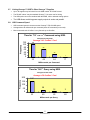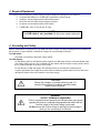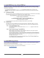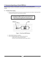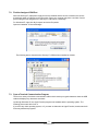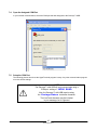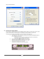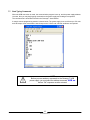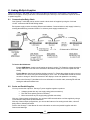
1
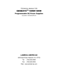
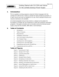
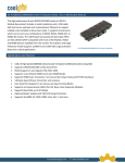
USER MANUAL FOR
USB Interface
GENESYS™ POWER SUPPLIES
Document: 83-033-800 Rev A
TDK-Lambda Americas Inc.
High Power Division
405 Essex Road, Neptune, NJ 07753
Tel: (732) 922-9300
Fax: (732) 922-9334
Web: www.us.TDK-Lambda.com/HP
Table of Contents
WARRANTY ................................................................................................................................2
SAFETY.......................................................................................................................................2
1. General Information .............................................................................................................3
2. Specifications .......................................................................................................................4
2.1.
USB Specification......................................................................................................................4
2.2.
Rear Panel Specifications..........................................................................................................4
2.3.
Front Panel Specifications .........................................................................................................4
2.4.
USB Drivers...............................................................................................................................4
2.5.
Software Support.......................................................................................................................4
2.6.
USB Command Set ...................................................................................................................4
2.7.
Linking Genesys™ USB To Other Genesys™ Supplies............................................................5
2.8.
USB Command Speed ..............................................................................................................5
3. Required Equipment ............................................................................................................6
4. Grounding and Safety ..........................................................................................................6
5. Install USB Drivers for a Virtual COM Port ........................................................................7
5.1.
Installation CD-ROM..................................................................................................................7
5.2.
Install Drivers.............................................................................................................................7
6. Install USB Library Drivers ..................................................................................................7
7. Communicating Using a Virtual COM Port ........................................................................8
7.1.
Setup the Power Supply ............................................................................................................8
7.2.
Find the Assigned COM Port .....................................................................................................9
7.3.
Open a Terminal Communication Program ...............................................................................9
7.4.
Open the Assigned COM Port .................................................................................................10
7.5.
Setup the COM Port ................................................................................................................10
7.6.
Get the Power Supply Address................................................................................................11
7.7.
Start Typing Commands ..........................................................................................................12
8. Linking Multiple Supplies ..................................................................................................13
8.1.
Communication Daisy-Chain ...................................................................................................13
8.2.
Series and Parallel Supplies....................................................................................................13
1
83-033-800 Rev A
WARRANTY
The warranty for the power supply, as described in the Genesys™ User Manual, also applies to the
USB option that is installed in the power supply.
SAFETY
The safety requirements and warnings for the power supply, as described in the Genesys™ User
Manual, also applies to the USB option that is installed in the power supply.
WARNING
OUTPUT TERMINALS GROUNDING
There is a potential shock hazard at the USB port when using power
supplies with rated or combined voltage greater than 400V and the
Positive Output of the Power Supply is grounded.
Do Not connect the Positive Output to ground in a power supply in which
you are connecting to a USB port.
2
83-033-800 Rev A
1. General Information
TM
The Universal Serial Bus (USB) option for the Genesys series power supply allows the user to remotely
program, measure and check status of the power supply. It uses a USB connection like those commonly used to
connect computers to many types of equipment.
Communication is achieved by installing USB drivers and making the USB connection to the power supply.
There are two types of USB drivers available:
A). Drivers that will make the USB connection appear as a new serial port in your computer.
B). Library files to allow a program to directly connect to the USB without creating a new serial port.
The USB command set, capabilities and speeds are identical to the RS-232/485 command set. This is described
in detail in the User Manual for the Genesys™ product line.
Although communicating through the USB can be as simple as typing commands into a terminal program
(example: Windows HyperTerminal), TDK-Lambda also provides a variety of drivers, example programs and
support for the USB.
3
83-033-800 Rev A
2. Specifications
2.1. USB Specification
•
USB 2.0 compliant.
•
Bus powered: requires +5V DC power from the driving port.
•
Maximum USB cable length: 16 feet (from USB 2.0 spec).
•
USB signal and shield grounded to power supply chassis.
2.2. Rear Panel Specifications
•
“B” Type USB socket, four pins.
•
DIP switch to enable or disable the USB port.
•
Enable USB. Also disables RS-232 and RS-485 IN.
•
Disable USB. Allows RS-232 and RS-485 with daisy chaining.
•
All other rear panel features are the same as the standard Genesys™ power supply.
2.3. Front Panel Specifications
•
On power-up, when USB is enabled, front panel shows “USb” for three seconds.
•
Settable serial address (0 to 30) for daisy-chaining many supplies to one USB port.
•
All other front panel features are the same as the standard Genesys™ power supply.
2.4. USB Drivers
•
Most common drivers available on the Genesys™ Driver CD-ROM.
•
Additional drivers available for download from http://www.ftdichip.com.
•
Support for a variety of operating systems: Windows, Mac OS, Linux and Windows CE.
2.5. Software Support
•
The USB power supply may be installed as a Virtual COM port (VCP). This allows the USB supply to
appear as an additional COM port (i.e. RS-232 port) available to the PC. Application software can
access the USB supply in the same way as it would access a standard COM port.
•
There is full support for COM ports including:
•
You may send commands with programs such as HyperTerminal.
•
Any programming language may use the native operating system drivers for the COM port.
•
TDK-Lambda has Test and Measurement drivers including IVI-COM, IVI-C and native LabView.
•
There is a USB driver library (DLL) called D2XX drivers. These allow your application program can make
direct communication to the Genesys™ USB without creating a virtual COM port.
•
There is support for the USB D2XX driver library including:
•
The library drivers are available on the Genesys™ Driver CD-ROM.
•
Library compatible with Windows, Mac OS and Linux.
•
See http://www.ftdichip.com for additional support.
2.6. USB Command Set
•
Uses serial command set with abbreviated commands. For example, send “PV” to program the voltage.
•
Uses same commands as the standard Genesys™ power supply for RS-232/485.
•
Commands are not SCPI compliant.
4
83-033-800 Rev A
2.7. Linking Genesys™ USB To Other Genesys™ Supplies
•
Up to 30 supplies may be linked from one USB ‘master’ to RS-485 ‘slaves’.
•
The RS-485 ‘slaves’ may be standard Genesys™. No extra cost for linking.
•
The USB option cannot be combined with the IEMD, LAN or Isolated Analog options.
•
The USB allows combining power supply outputs in series and parallel.
2.8. USB Command Speed
•
USB command speed is the same as the Genesys™ RS-232/485 speed
•
Average about 40 milliseconds per command (about 25 commands per second).
•
Most commands take 33 mSec. A very few take up to 80 mSec.
Time for "PV nn.n" Command using USB.
Frequency
Histogram for 200 Cmds
120
100
80
60
40
20
0
Average = 41.5 mSec / Cmd
105
68
26
1
33
49
64
71
Milliseconds per Command
Time for "MV?" Query using USB.
Histogram for 200 Cmds
Average = 36.6 mSec / Cmd
Frequency
200
157
150
100
28
50
12
3
65
80
0
33
49
Milliseconds per Query
5
83-033-800 Rev A
3. Required Equipment
To remotely control a Genesys™ power supply through the USB, the following items are required:
a. Computer with USB port, or a USB hub to expand the number of ports.
b. Genesys™ power supply with the USB interface option.
c. Driver disk from the power supply shipping container.
d. AC power cord as required by the power supply.
e. A USB cable, Type “A” plug to type “B” plug
NOTE
The USB cable is not provided with the power supply shipping kit.
4. Grounding and Safety
Special consideration must be given to your USB connection to make sure the grounding scheme is understood
and to ensure no ground offsets or hazardous voltages can cause damage to the port.
The USB Shield:
The shield is connected to the power supply chassis.
The USB Signals:
For the GENH, GEN 1U and GEN 2U power supplies: the USB signal lines are connected Safety Extra
Low Voltage (SELV) ground. This is isolated from the chassis and the outputs, but the ground is tied to
the J1 analog connector on the pins 1 and 14 side.
For the GEN 3U (10 KW and higher): the USB signal lines are connected to chassis ground.
In power applications where high currents are switched suddenly, ground offsets can occur that could
damage the USB circuits in the controller or the power supply.
CAUTION
Where high voltages or currents are being used, it is
strongly recommended to install an electrical isolator
device into the USB line.
WARNING
OUTPUT TERMINALS GROUNDING
There is a potential shock hazard at the USB port when using power
supplies with rated or combined voltage greater than 400V and the
Positive Output of the Power Supply is grounded.
Do Not connect the Positive Output to ground in a power supply in
which you are connecting to a USB port.
6
83-033-800 Rev A
5. Install USB Drivers for a Virtual COM Port
To control your Genesys™ power supply through the USB port, it is a simple solution to install it as a Virtual
COM Port (VCP). This gives you the same utilities, libraries and support as is given to your computer’s legacy
serial port (i.e. RS-232 port).
For a Windows operating system, CDM20600.exe is an installation package which is referred to as a
Combined Driver Model (CDM). It installs the Virtual COM Port (VCP) drivers along with the driver library
(D2XX ).
5.1. Installation CD-ROM
When you insert the Genesys™ USB Driver Disk into your computer’s drive, it should auto-run and display
a document with information on the available drivers and installation guides.
If the CD-ROM auto-run does not launch, then double-click “Index_00.htm” on
the disk to launch your web browser.
You may read the installation guides by navigating to the
“\USB Driver Installation Guides\...” folder and opening the PDF guides.
Adobe Acrobat Reader is required.
It is recommended to browse the Driver Installation Guides folder on the CD-ROM.
5.2. Install Drivers
The USB drivers may be installed before connecting the Genesys™ USB power supply, or you may
connect the power supply first and have the computer prompt you to search for and install the drivers.
5.2.1. If you Install Software First
For a Windows system, it is recommended run the CDM20600.exe program to install driver
revision 2.06.00.
5.2.2. If you Connect Genesys™ with USB First
Before powering up the Genesys™ supply, enable the USB port by moving the rear-panel
switch to DOWN, as shown below in section TBD.
For some operating systems, a “Found new hardware” wizard will pop up when the Genesys™
USB is connected and detected. When it appears, have the wizard search the CD-ROM for the
appropriate folder that has the driver files.
An example folder may be: E:\USB Drivers\Driver - MS Windows Certified\...
For a Windows system, the installation wizard will run twice: once to install the USB link and
once to install the virtual comm port (VCP).
6. Install USB Library Drivers
If you are writing your own application program to control the Genesys™ power supply through the USB port,
you will need to include the D2XX libraries.
These library function calls are documented in CD-ROM: USB D2XX Programmer's Guide.pdf
Additional programming support may be found on the FTDI website:
http://www.ftdichip.com/
7
83-033-800 Rev A
7. Communicating Using a Virtual COM Port
A quick test for the Genesys™ USB connection is to use a serial port communication program.
The below example is specific to the Windows operating system. Customers with other O.S. can find equivalent
methods.
7.1. Setup the Power Supply
a. Before turning the Genesys™ AC power on, set the rear panel 2-pole switch to enable the USB. It
is sufficient to slide either of the two poles to DOWN.
NOTE
The Genesys™ USB connection will be detected by the
computer as soon as the USB cable connection is made,
even if the power supply has no AC power applied
Figure 1. Rear Panel USB Features
b. Switch ON the Genesys™ AC power.
c. See the front panel display show “USB” for three seconds.
If “USB” does not show on the front panel,
check the rear panel USB Enable switch (shown above)
8
83-033-800 Rev A
7.2. Find the Assigned COM Port
When the Genesys™ USB power supply drivers are installed and the device is detected, the drivers
dynamically assign a COM port to the connection. Since your computer may have a number of serial
ports, finding the one assigned to the Genesys™ USB can be a challenge.
For Windows XP, right-click My Computer and select Properties.
Open the Hardware Device Manager:
The following picture shows that the Genesys™ USB has been installed as COM4.
7.3. Open a Terminal Communication Program
There are a variety of terminal communication utilities which sends your typed characters down the USB
cable and displays any characters sent back.
Up through Windows XP, the HyperTerminal program was installed with the operating system. The
following pictures are taken from it.
If you have any other operating system, or if you want an alternative to HyperTerminal, a web search will
find many alternative programs.
9
83-033-800 Rev A
7.4. Open the Assigned COM Port
In your terminal communication, select the COM port that was assigned to the Genesys™ USB:
7.5. Setup the COM Port
The following pictures show how the HyperTerminal program is setup. Any other communication program
must use similar settings.
NOTE
The Genesys™ with USB will only communicate using a
COM port setting of 19200 BAUD.
Also, the Genesys™ with USB requires using
the Carriage Return terminator character.
The Line Feed character may be included
in your message, but it is ignored
10
83-033-800 Rev A
Setup controller COM Port:
7.6. Get the Power Supply Address
Every Genesys™ power supply has a serial COMM port address which is a number from 0 to 30. In order
to open communication to a power supply, the addressing command “ADDR nn” must be sent.
To see your power supply’s serial address, go to the front panel of the supply and:
A.
B.
C.
If the “REM/LOC” LED is illuminated, briefly press and release the REM/LOC button to
put the supply into Local mode.
If the button does not respond, the supply has been set to Local Lockout.
In this case, cycle the AC power and try again.
Press and hold the REM/LOC button for three seconds.
See the front panel shows the serial address and “USb”.
Remember this address for the next step.
In this picture, the address is 6 (the factory default).
11
83-033-800 Rev A
7.7. Start Typing Commands
When the USB connection is made, the communication program is set up, and the power supply address
is known, then you may begin typing commands to the power supply and reading the responses.
The command set is described in detail in the Genesys™ User Manual.
A sample remote programming session is shown below. The power supply is set to deliver up to 5.0 volts
and 100 amps. It has measured the actual output to be 5.0015 volts. No fault conditions are reported.
NOTE
Before you can send any commands to the Genesys™ USB
power supply, you must send the address command ADR nn
and an “OK” response must be returned.
12
83-033-800 Rev A
8. Linking Multiple Supplies
Using one Genesys™ with USB, you can control more than one Genesys™ power supply. The connection
between the supplies can be just to share a communication port, and/or you can connect the outputs for series
or parallel supplies.
8.1. Communication Daisy-Chain
One Genesys™ with USB can be used to control a whole chain of supplies by using the J3-IN and
J3-OUT connectors with RS-485 linking cables.
Each power supply must be set with a different serial address. Communication to each supply is done by
sending the addressing command “ADR nn” to select a power supply at address “nn”.
To Set the Serial Address:
For the USB Master: view the serial setting as shown in section 7.6. Rotate the voltage encoder to
set any address 0 to 30. Wait a few seconds for the address display to clear and update the new
setting.
For the Slaves: view the serial setting similar to section 7.6. Rotate the voltage encoder to set any
address 0 to 30. ALSO verify the current display is set to “19.2” for 19200 Baud. Rotate the current
encoder to change it. Wait a few seconds for the display to clear and update the new setting.
Refer to the Genesys™ User Manual for more information on the link cable, selecting RS-485 and
setting the address and Baud rate.
8.2. Series and Parallel Supplies
You may connect the outputs of Genesys™ power supplies together to produce:
Voltages greater than any one supply rating (series connection).
Plus and minus polarity (series connection).
More current than any one supply rating (parallel connection).
With any of these output configurations, you can have USB communication to all the supplies by using a
communication daisy-chain as described above.
With any of these output configurations, you can use the features of an analog control chain, a shut-off
daisy-chain or Advanced Parallel.
Refer to the Genesys™ User Manual for more information on series and parallel supplies and their
features and warnings.
13
83-033-800 Rev A
This page left intentionally blank.
14
83-033-800 Rev A