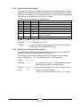
1
USER MANUAL FOR LAN Interface GENESYS™ POWER SUPPLIES Document: 83-034-100 Rev F Applies To: This document applies to LAN cards with a firmware revision that ends in: LAN:2.1 TDK-Lambda Americas Inc. High Power Division 405 Essex Road, Neptune, NJ 07753 Tel: (732) 922-9300 Fax: (732) 922-9334 Web: www.us.TDK-Lambda.com/HP Table of Contents 1. 2. 3. 4. 5. 6. 7. GENERAL INFORMATION ....................................................................................... 4 1.1. Introduction .................................................................................................... 4 1.2. Feature Summary .......................................................................................... 5 SPECIFICATIONS .................................................................................................... 6 2.1. Power Supply Specifications .......................................................................... 6 2.2. LAN Specifications ......................................................................................... 6 2.3. LAN Command Speed ................................................................................... 8 SELECT THE CONTROL METHOD ......................................................................... 9 3.1. 3.2. A Variety of Control Methods ......................................................................... 9 LAN, Local, or Serial ...................................................................................... 9 3.3. LAN Option Rear Panel View ....................................................................... 10 CONNECT TO NETWORK...................................................................................... 12 4.1. LAN Cable ................................................................................................... 12 4.2. Types of Networks ....................................................................................... 12 4.3. Power-up the LAN Power Supply ................................................................. 13 4.4. 4.5. IP Addresses................................................................................................ 14 Hostnames ................................................................................................... 15 LAN SETUP ............................................................................................................ 16 5.1. View the IP and MAC Addresses ................................................................. 16 5.2. Change the IP Address ................................................................................ 16 5.3. LAN Reset ................................................................................................... 17 5.3. LAN Reset ................................................................................................... 17 5.4 Default Lan Settings ..................................................................................... 18 WEB PAGES........................................................................................................... 19 6.1. 6.2. Benefit of Web Pages .................................................................................. 19 Opening the HOME Page............................................................................. 19 6.3. The HOME Page .......................................................................................... 20 6.4. 6.5. Logging In .................................................................................................... 21 DC Power Page ........................................................................................... 22 6.6. LAN Page .................................................................................................... 25 6.7. HELP Page .................................................................................................. 28 PROGRAMMING USING VISA DRIVERS .............................................................. 29 7.1. VISA Description .......................................................................................... 29 7.2. VXI-11 Compatibility..................................................................................... 29 7.3. Opening the VISA Connection ..................................................................... 29 7.4. Communicating Using VISA ......................................................................... 29 1 83034100 Rev F 8. 9. 10. 11. 12. PROGRAMMING USING IVI DRIVERS .................................................................. 30 8.1. IVI Description.............................................................................................. 30 8.2. IVI Support ................................................................................................... 30 PROGRAMMING USING SOCKETS ...................................................................... 31 9.1. 9.2. Socket Description ....................................................................................... 31 Communicating Using Sockets..................................................................... 31 9.3. Special Requirements for Socket Programs ................................................. 31 9.4. Controller Access: Single and Multiple Clients ............................................. 31 9.5. 9.6. Input Buffer Requirements ........................................................................... 32 Message Terminators .................................................................................. 33 9.7. Using TCP Sockets ...................................................................................... 33 9.8. Using UDP Sockets...................................................................................... 33 9.9. Other Ports .................................................................................................. 33 CONNECTING OVER WAN .................................................................................... 34 10.1. View Web Pages Over WAN ........................................................................ 34 10.2. Use Sockets Over WAN ............................................................................... 34 SCPI COMMAND REFERENCE ............................................................................. 35 11.1. 11.2. Command Syntax ........................................................................................ 35 Configuring the Output ................................................................................. 36 11.3. Measuring the Output................................................................................... 37 11.4. Operating Modes ......................................................................................... 38 11.5. Output Protection ......................................................................................... 39 11.6. LAN Specific Commands ............................................................................. 41 11.7. Common Commands ................................................................................... 43 11.8. Error and Status Commands ........................................................................ 45 RS-485 MULTI-DROP COMMANDS ....................................................................... 54 12.1. Introduction .................................................................................................. 54 12.2. 12.3. Configure the LAN Supply ............................................................................ 55 Connect and Configure the RS-485 Supplies ............................................... 55 12.4. Multi-drop Programming Using SCPI Commands ........................................ 56 13. SYSTEM:ERROR? MESSAGES............................................................................ 59 14. SAMPLE PROGRAMS ............................................................................................ 61 14.1. Web Downloads ........................................................................................... 61 14.2. Customer Support ........................................................................................ 61 2 83034100 Rev F 15. TROUBLESHOOTING ............................................................................................ 62 15.1. Cannot See the IP Address, LAN Status LED Stays Red ............................ 62 15.2. 15.3. IP Address is All Zeroes, LAN Status LED Stays Red ................................. 62 IP Address is Three Zeroes and a Number .................................................. 62 15.4. Cannot Communicate to the Power Supply .................................................. 63 15.5. Cannot View Web Pages Over a Peer-to-Peer Network ............................... 63 15.6. Cannot Open Web using Laptop or Dual-LAN Card Computer ..................... 63 15.7. Web Page Fields Show as Little Blocks ....................................................... 64 15.8. Web Page “Refresh List” Does Not Find Slave Supplies .............................. 64 15.9. Cannot Connect Using Hostname ................................................................ 65 15.10. Web Page “Modify Settings” Does Not Work ................................................ 65 16. GLOSSARY ............................................................................................................ 66 Table of Figures Figure 1. Front Panel LAN Features ................................................................................ 4 Figure 2. Rear Panel LAN Features ................................................................................. 4 Figure 3. Rear Panel LAN Features ............................................................................... 10 Figure 4. Server Network Connection Diagram .............................................................. 12 Figure 5. Peer-to-Peer Connection Diagram .................................................................. 13 Figure 6. Web HOME Page ........................................................................................... 20 Figure 7. Error and Status Registers .............................................................................. 48 Figure 8. Configuring a Multi-drop System of Supplies................................................... 54 3 83034100 Rev F 1. GENERAL INFORMATION 1.1. Introduction The Local Area Network (LAN) option for the GenesysTM series power supply allows the user to remotely program, measure and check status of the power supply. It uses an Ethernet connection like those used to connect computers to each other and to the Internet A computer’s web page browser may be used to operate the power supply through a builtin web page server. For applications including factory and test automation, communication may be done using several standard network protocols and instrument commands Refer to the GenesysTM Technical Manual for information on installing the power supply, safety requirements, specifications, connecting the power-in and out, operating the front panel, using the serial (RS-232/485) programming and the analog (J1) programming Figure 1. Front Panel LAN Features Figure 2. Rear Panel LAN Features 4 83034100 Rev F 1.2. Feature Summary A. Communicate over any standard TCP/IP network 1. LAN (Local Area Network) 2. WAN (Wide Area Network) 3. Communicate across the world using the Internet B. Web page viewable with any web page browser, such as Internet Explorer 1. Configure the network connection settings 2. Active web page (GUI) that programs and reads the power supply output and status 3. Security settings to block multiple controllers and risky protocols. 4. Optional password protection prevents unauthorized operation C. LAN Protocols 1. VISA drivers, TCP and UDP sockets are supported. 2. VXI-11 Discovery and ping server are supported D. LXI Class C 1. Conforms to LXI standards (revision 1.1) for network configuration 2. A “LAN Status” indicator shows when the network connection is established 3. IVI-COM and IVI-C drivers are available for download 4. Easily write custom automation programs E. Full remote programming functions 1. Uses SCPI command language, an instrumentation standard 2. Compatible with VISA drivers an all the test & measurement utilities 3. TCP and UDP sockets will support PLCs, Linux and other non-VISA controllers F. Front Panel features 1. View IP and MAC address on front panel 2. Set the complete IP address on front panel 3. LAN Reset on front panel 4. User may remotely “Blink” the front panel to locate a power supply in a rack G. Rear Panel features 1. Ethernet RJ-45 connector (standard 8-pin phone jack for LAN) 2. Link and Activity LED on RJ-45 connector nd 3. LAN Status LED shows LAN fault and is a 2 “Blink Identify” on rear panel 4. A switch disables the LAN to allow use as an RS-485 Multi-drop slave H. RS-485 Multi-drop Chain 1. Allows connecting up to 30 power supplies using simple Link cable 2. One LAN IP address shared by all RS-485 power supplies 3. The LAN option is not needed in the RS-485 power supplies, but they must be Multi-drop enabled Trademark Notices LXI is a trademark of the LXI Consortium Inc. Microsoft and Windows are trademarks of Microsoft Corporation 5 83034100 Rev F 2. SPECIFICATIONS 2.1. Power Supply Specifications When using the LAN, the power supply ratings and accuracies are the same as for the digital remote programming using RS-232 or RS-485. See the Technical Manual for Genesys™ Power Supply for those specifications 2.2. LAN Specifications ELECTRICAL Ethernet Auto-MDIX Auto-Negotiate Meets IEEE 802.3u specifications Accepts patch or cross-over cable connection Selects fastest of 10Base-T or 100Base-T networks (10 or 100 Megabits per second) NETWORK CONFIGURATION MAC Address IP Address DHCP Auto-IP Static IP TDK-Lambda assigned: 00:19:f9:xx:xx:xx View or set (with restrictions) from front panel Get address from network server. Leasing services Create own IP address: 169.254.xx.xx Any IP fixed by operator Hostname Duplicate IP Detection Subnet Mask Default Gateway DNS Server LAN Reset NetBIOS, ARP and rARP protocols. Operator settable name Reject duplicate setting or disconnect from network Mask set by DHCP or static Address set by DHCP or static Address set by DHCP Reset configuration from front panel or SCPI command LAN PROTOCOLS TCP IPv4 Instrument Protocols VXI-11 VISA TCP Sockets UDP Sockets VXI-11 Discovery SNMP Ping Server HTTP LAN packets follow Transmission Control Protocol Internet Protocol version 4 Supports Core channel, not Abort or Interrupt channels VXI-11 compliant, uses RPC and Portmapper, SCPI cmds Send SCPI commands to port 8003 Send SCPI commands to port 8005 Find connected instruments Verify LAN connection to instrument Web page server with Java scripts and applets COMMANDS SCPI IEEE-488.2 Serial Pass-Through SCPI 1999 compliant command, measure and status Condition and event register tree Send native RS-232 commands with abilities beyond SCPI WEB PAGES Multiple users Identity LAN Configuration Active Control GUI Send Commands Help Multiple web pages can be open at once Identify power supply model, serial number, revision etc. View and set LAN configuration Program and read output settings Send SCPI commands, read errors Link to TDK-Lambda web sites 6 83034100 Rev F SUPPLY CONFIGURATIONS Local Control LAN Remote Control RS-232/485 Control ‘J1’ Analog Control Series / Parallel Supplies Advanced Parallel Supply may be run from front panel even if LAN is monitoring Supply may be controlled and monitored through LAN LAN may be disabled to use the standard RS-232/485 ports LAN may monitor supply while analog controller sets output Rules for standard Genesys™ supplies apply to LAN supplies Rules for standard Genesys™ supplies apply to LAN supplies INDICATORS IP and MAC Address Multi-drop Address Link LED Activity LED LAN Status LED Blink Identify Local/Remote LED View addresses on front panel View RS-485 address on front panel Indicates the Ethernet cable connected at both ends Indicates when LAN packets detected Red/green, indicates power supply has valid IP connection Find the supply by remotely blinking front and rear LEDs Indicates if LAN has control of supply output BUTTONS, SWITCHES LAN Reset IP Address Multi-drop Address LAN/ RS Select Front panel button Change entire IP address on front panel Change RS-485 address on front panel Disable LAN to enable RS-232/485 or Multi-drop slave SECURITY Web Page Password Single Client Only Block UDP Sockets Disable VXI-11 Discovery Disable Ping Server COMPLIANCE LXI UL, IEC, TUV, CE, ROHS etc Can set password to prevent unauthorized or accidental changes to LAN settings or power supply output settings Set to prevent multiple programs from taking control Single client will block attacks through UDP sockets Stop intruders from finding the power supply Stop intruders from finding the power supply Certified for LXI (rev 1.1) class C instrument Conformances that are granted to basic power supply also apply to power supply with LAN installed 7 83034100 Rev F 2.3. LAN Command Speed The following communication speeds are typical values only. In addition to the variability in the Genesys™ LAN interface, there are timing variations within the controller and the network routing. The following speed specifications are subject to change without notice. VISA Drivers Speed Commands and queries sent using VISA drivers generally take 10 mSec longer than the same message sent using TCP sockets (in table below) UDP Sockets Speed Commands and queries sent using UDP sockets generally are 5 mSec faster than the same message sent using TCP sockets (in table below) TCP Sockets Speed Typical Command or query speeds: Most Commands and Queries ~ 85 mSec This includes all commands not listed below: :VOLT n.nn :VOLT? MEAS:VOLT? OUTP:STAT 1 OUTP:STAT? VOLT:LIM:LOW n.nn VOLT:LIM:LOW? SOUR:MOD? System Queries Examples: SYST:ERR? *ESR? ~ 30 mSec INST:SEL? Status Register Queries ~ 60 mSec Examples include: STAT:QUES:COND? STAT:OPER:COND? Instrument Select for Multi-drop ~ 230 mSec Example: INST:SEL nn Identity Query ~ 260 mSec Example: *IDN? 8 83034100 Rev F 3. SELECT THE CONTROL METHOD 3.1. A Variety of Control Methods The Genesys™ power supply with LAN is very flexible. In addition to the LAN, there are other ways the supply can be used. See the Technical Manual for Genesys™ Power Supply for more details on the local (front panel), serial (RS-232/485), or analog (J1) control. 3.2. LAN, Local, or Serial The power supply, with the LAN option installed, may be operated through four interfaces. This section describes how to enable each MODE MODE DESCRIPTION 1 LAN Control using an Ethernet connection LAN will disable the J3-IN serial port 2 Local Control using the front panel encoders and buttons LAN can be used to measure and read while in local mode 3 Serial Control using RS-232 and RS-485 through the J3-IN and J3-OUT connectors Serial will disable the LAN port 4 Analog Control using an analog signals to the 25-pin ‘J1’ connector LAN, local or serial may still be used to measure and set protections 3.2.1. Select Local (Front Panel) Mode The supply may be operated in the local, or front panel, mode even when a computer is using the LAN connection If the supply is in remote mode, the front panel “REM/LOC” LED is ON. The supply may be returned to local by pressing and releasing the “REM/LOC” button If the “REM/LOC” button will not go into local mode, then: If the LAN is being used to change settings, the supply will automatically go to remote with every command. Stop the LAN program and then press “REM/LOC” button The LAN computer may have sent a Local Lockout command. Use the LAN to send “SYST:SET LOC” (see section 11.4.2) or turn the supply AC off and on and then press the “REM/LOC” button 3.2.2. Select RS-232 & RS-485 (Serial) Remote Mode The serial (RS-232 & RS-485) remote control may be selected even if the LAN option is installed. The serial remote is described in the Technical Manual for the Genesys™ Power Supply. The LAN has similar capabilities as the serial remote, but the LAN SCPI programming language is not compatible with the serial language To select the RS-232 & RS-485 mode: A. Switch the supply AC power off B. Set the LAN card switch pin1 to DOWN (see Figure 3) C. For RS-232, set rear-panel SW1 pin 6 to DOWN. For RS-485, set SW1 pin 6 to UP D. Switch the supply AC power on. The front panel will not show “Lan” at startup 9 83034100 Rev F 3.2.3. Select LAN Remote Mode Selecting the LAN mode will allow programming over the Ethernet cable. Any settings and measurements may be done from a remote computer using the power supply’s built-in web pages or using SCPI programming To select the LAN mode: A. Switch the supply AC power off B. Set the LAN card switch pin1 to UP (see Figure 3) C. Switch the supply AC power on. The front panel will show “Lan” at startup 3.3. LAN Option Rear Panel View The power supply rear panel, with the LAN option installed, is shown below. Figure 3. Rear Panel LAN Features 3.3.1. LAN Enable Switch: This two-pole DIP switch allows you to select the LAN or the RS-232/485 mode. The switch on the left is the only one used Note The supply’s AC power must be OFF to change this switch. The change is only detected during the supply’s power-up sequence SWITCH UP: select the LAN mode. The power supply shows “Lan” at power-up. The rear panel J3-IN port for RS-232/485 does not operate. The J3-OUT port may be used to start a multi-drop chain of supplies (see section 12) Note When using the LAN, always set the supply to RS-232 mode by setting rear panel SW6 bit 6 to DOWN. See section 12.2 for details SWITCH DOWN: select the RS-232/485 mode. The power supply does not show “Lan” at power-up. The rear panel J3 ports for RS-232 and RS-485 do operate. The power supply may be used in a chain of multi-drop supplies (see section 12). See the Technical Manual for the Genesys™ Power Supply for the description of the RS-232/485 mode 10 83034100 Rev F 3.3.2. Link and Activity LED: this small LED, embedded in the RJ-45 socket, glows green when the connection is made to an active network and it blinks when any message packets are detected 3.3.3. Collision LED: this small LED, embedded in the RJ-45 socket, blinks amber when the LAN packets are corrupted by collisions 3.3.4. LAN Status LED: This is a two-color LED to the left of the RJ-45 connector. It shows: Normal Operation: Steady green. The power supply has an active LAN connection Device Identify: Blinking green. The identify function is turned on from a remote computer using the web page or a SCPI command. The front panel blinks along with the rear. It is used to identify one power supply in a rack of instruments. The blinking is turned off by the web page, by sending another SCPI command, or by changing any front panel control. In multi-drop chain, only the master LAN supply blinks. LAN Fault: Steady red. Shows the LAN mode is not enabled, the LAN connection was never made, or that the LAN connection was made and then broken. 11 83034100 Rev F 4. CONNECT TO NETWORK 4.1. LAN Cable The LAN cable must be supplied by the customer. It may be a standard straight “patch” CAT-5 (or better) network cable or it may be a “crossover” cable where the pins are reversed on one end. The cable type is auto-detected by the power supply Note The serial link cable (0.5 m long) provided with the Genesys™ power supply cannot be used for a LAN connection 4.2. Types of Networks There are basically two types of networks that are discussed here: B. NETWORK WITH A SERVER: this is the typical local area network with a server computer and network administrator to keep it running. The server will download the IP address and other settings to the power supply Figure 4. Server Network Connection Diagram 12 83034100 Rev F B. PEER-TO-PEER NETWORK: this is typically the situation when you connect the Genesys™ supply directly to a computer that is not a network server. The power supply will configure its own IP address and other settings Figure 5. Peer-to-Peer Connection Diagram 4.3. Power-up the LAN Power Supply The Genesys™ power supply LAN option will automatically detect if it is connected or disconnected from a network. It will also automatically look for a network server and it will get or create an IP address. It will also broadcast its IP address and hostname to all other devices on the network. A. Before turning the power supply ON, verify it is set to enable LAN. See the switch setting in section 3.3.1 B. Turn ON the power supply AC power. See the front panel show “Lan” for about 3 seconds. After that, the supply will show “OFF” or the last output settings C. The LAN cable may be connected before or after the supply is switched on D. For a server network, wait about 15 seconds. See the rear panel LAN Status LED turns green. E. For a peer-to-peer network, wait about 40 seconds. See the rear panel LAN Status LED turns green. The computer screen may show a LAN notification bubble, “This connection has limited or no connectivity.” When the LAN Status LED turns green, the power supply IP address will change from all zeroes to a valid address. It can be viewed on the front panel (see section 5.1) Note If the LAN Status LED does not turn green, see section 15 for troubleshooting steps. 13 83034100 Rev F 4.4. IP Addresses The simplest and most reliable way to open a network connection is with the power supply’s IP address. This is a group of four numbers separated by periods (for example: 10.1.15.123). This IP address may be viewed from its front panel (see section 5.1) There are three modes which the power supply can get an IP address, as show in this table: IP Address DHCP Auto-IP Static IP Mode Select DHCP is default after “LAN Reset” Default after “LAN Reset” if no DHCP server is used May be set in the “LAN Modify” web page (see 6.6.2) or by setting the IP-4 address on the front panel (see 5.2) Assignment Assigned by the network server Assigned by the power supply Assigned in the “LAN Modify” web page (see 6.6.2) or by setting the IP-4 address on the front panel (see 5.2) Range Any address 169.254.xxx.xxx Any address Lifetime Address may change as the DHCP server assigns addresses dynamically to many instruments Fixed for the power supply, except if an address collision is detected Always fixed for the power supply Duplicate Addresses The DHCP server should prevent duplicate IP addresses Finds another available auto-IP address Disconnect from the network and the LAN Status LED stays red 14 83034100 Rev F 4.5. Hostnames The hostname is an address in the form of text instead of numbers (for example: GEN3025-29B). This address mode is less common than the IP address because the hostname cannot be viewed from its front panel, and because a naming service (such as NetBIOS) must be running in the LAN computer. A custom hostname can be created through the web pages (see section 6.6.2). For example, if the hostname is changed to “Heater_3” then a control program can send a command to Heater_3 and it is easy understand. After a “LAN Reset” is done (see section 0), the power supply will create a default hostname based on the model and serial number of the supply. The default hostname is in the format: < Product > < Voltage rating > – < Current rating > – < last 3 digits of serial number > If the rating has a decimal point, substitute “p” for the decimal point. For example, Model Serial Number Default Hostname GEN8-180-LAN 08J4210B GEN8-180-10B GEN600-2.6-LAN 15M3229J GEN600-2p6-29J GENH12.5-60-LAN 37B12830E GENH12p5-60-30E The power supply may be set to one of three network modes, each with a different way to use the hostname. This is shown in the table below Hostname DHCP Auto-IP Static IP Default Hostname GENvv-aa-nnn (see above) GENvv-aa-nnn (see above) None, hostname cannot be used Hostname Protocol Hostname by NetBIOS Hostname by NetBIOS None, hostname cannot be used Hostname on Web Pages Shows IP address on “Home” page (Note 1) Shows hostname on “LAN Configure” page Shows IP address on “Home” page (Note 1) Shows hostname on “LAN Configure” page Shows IP address on “Home” page Hostname disabled on “LAN Configure” page Note 1: The hostname will show on web “Home” page if both DNS and rDNS services are running on the network. 15 83034100 Rev F 5. LAN SETUP 5.1. View the IP and MAC Addresses When the power supply is running with the LAN enabled, the IP and MAC addresses may be viewed on the front panel by following these steps: A. Press and hold the FOLD button for three seconds. The 7-segment displays will show something such as: IP-1 010 By turning the voltage encoder, the complete IP and MAC addresses may be seen. All four numbers of the IP address may be changed through the web pages or from the front panel (see next section). The MAC address cannot be changed. The IP may not show on display if faults, such as Enable or Shut-Off, are in progress. Rotate voltage knob IP-1 10 IP-2 225 IP-3 26 IP-4 38 AC-1 00 AC-2 19 AC-3 F9 00:19:F9:27:D3:B0 AC-4 27 (“AC” is short for “MAC”) AC-5 d3 AC-6 b0 In this example, – the IP address is: 10.225.26.38 – the MAC address is: B. If the voltage knob is not changed for five seconds, the supply will revert to the normal voltage and current displays. If this happens, press and hold the FOLD button again 5.2. Change the IP Address The LAN with revision after 2.0 allows you change all four numbers (octets) of the IP address from the front panel. The IP address has four numbers (ex: “192.168.53.44”). Each number may be set to any value from 1 to 254. The power supply must be set to Local Mode to allow changing the IP address. A. Press and hold the FOLD button for three seconds. The 7-segment displays will show something such as: IP-1 192 “192” is the 1st number in the address. B. Rotate the voltage encoder until the display shows something such as: IP-3 53 “53” is the 3d number in the address. C. Rotate the current encoder to change the 3d number in the address: IP-3 “60” is the new 3d number. 60 16 83034100 Rev F D. To apply the new address, momentarily press the “FOLD” button. See the display shows for a few seconds: LAn Hold This shows the LAN connection is on hold while acquiring the new address. If you do not press “FOLD” soon enough, the display returns to normal and the old address is kept. If another device already has the address you are trying to set (duplicate addresses), then after “Lan Hold” clears, the front panel will blink and the address will return to what it was before the change was made. Note When you change the IP address from the front panel, the Genesys™ LAN will switch to STATIC addressing. ( DHCP and Auto-IP addressing will be disabled) 5.3. LAN Reset If it is necessary to reset the supply to the factory default LAN settings, use the front panel to: A. Press and hold the OVP/UVL button for 2 seconds B. The 7-segment displays will show: This display may not show if faults, such as LAn rES Enable or Shut-Off, are in progress C. Release the OVP/UVL button D. Briefly pressed and release the OVP/UVL button again. E. The displays will briefly show: rES 0000 and the LAN will be reset to the default settings (listed below). If the OVP/UVL button is not pressed again, the LAN settings will not be reset F. It may be required to AC cycle the power supply off and on. This ensures a new network connection is established with the reset values 17 83034100 Rev F 5.4. Default Lan Settings DHCP is enabled If DHCP fails to get a lease, the auto-IP settings will be obtained: IP address: 169.254.xxx.xxx (see section 4.4) Subnet mask: 255.255.0.0 Default gateway 0.0.0.0 DNS Server 0.0.0.0 Hostname: GENvvv-aaa-sn (see hostname in section 4.5) Description: “Genesys Power Supply” Controller Access One Client Only Ping Server: Enabled Keep-Alive 1800 Seconds (30 minutes) Auto-Negotiate: Automatically select network speed VXI-11 Discovery Password: Enabled None 18 83034100 Rev F 6. WEB PAGES 6.1. Benefit of Web Pages The GenesysTM web pages are useful for: Reading the supply’s model, identity, revision and LAN setup information Configuring the LAN connection Programming and reading the supply’s DC output This is all done graphically. There are no commands to look up 6.2. Opening the HOME Page Once the rear panel LAN Status LED has turned green (see Section 3.3.4), you may open the GenesysTM web page A. Read the IP address from the supply’s front panel by holding the FOLD button (see section 5.1 for details) B. Open a web page browser program such as Internet Explorer or Netscape Navigator. Type the power supply’s IP address as shown below. Click the GO button The power supply’s Home page will appear. If it does not, see Troubleshooting section 15 C. Alternately, the hostname may then be used for addressing the web page as shown below (if the power supply is set for “DHCP/Auto-IP”, and if NetBIOS naming service is running on the computer). See Section 4.5 for a description of the hostname The power supply’s Home page will appear. If it does not, see Troubleshooting section 15 19 83034100 Rev F 6.3. The HOME Page The following page appears when the web page is first opened or when it is refreshed: Figure 6. Web HOME Page VISA Name Using IP Address: For automation programming, VISA is a type of communication driver. For LAN instruments, the IP address may be used in the VISA resource descriptor. See section 7. VISA Name Using Hostname: For automation programming, an alternate VISA resource descriptor using the power supply’s hostname. See section 4.5. RS-485 Address: This address only applies to a multi-drop chain of supplies. This is the RS-485 address of the LAN supply (also called the master supply). To set this address on the front panel, see section 12.2.2 Hostname: A unique name for a device on a network. The default hostname is described in section 4.5 and it is configured in section 6.6.2. If the hostname is not registered with the network name server using reverse-DNS (rDNS), then the IP address will be shown here. Auto-MDIX: The LAN will automatically detect if a patch or cross-over LAN cable is used Auto-Negotiate: The LAN will automatically adjust its speed to the fastest available 20 83034100 Rev F 6.4. Logging In To change power supply output or the LAN settings, a user must first log in. Click the “Login” button at the top-left side of the web page and a pop-up window appears. The only acceptable user name, “admin”, is shown. The password may be set or removed on the LAN Users web page. A front panel LAN Reset will clear the password (see section 0). 21 83034100 Rev F 6.4.1. 6.5. Login Rules Any number of users may view the web pages of a power supply at the same time. However, the update rate becomes slower as more web pages are opened. Only one user at a time may be logged-in to modify the power supply settings If an automation program with VISA or socket connection is running, then you may view the web pages but you cannot login to change any settings If a user is logged in, then a VISA or socket connection cannot be opened by an automation program A user may logout by clicking the “Logout” button, by closing the web browser or by leaving the web browser idle for “LAN Keep-alive” seconds (see section 6.6.3) DC Power Page When the “DC Power” tab is clicked, the following web page opens. This page, and its sub-menus, allow you to operate the power supply and adjust its output settings 6.5.1. DC Power Output Page When the “DC Power” tab is selected, the “Output” soft front panel (GUI) loads first. First, select the desired power supply with: Refresh List: When this button is clicked, the web page will scan to find connected Multi-drop power supplies and put the discovered addresses into the listbox. This button only applies to a multi-drop chain as described in section 12. 22 83034100 Rev F Select RS-485 Multi-drop Address: This address is described in section 12.2.2. This address only applies to a multi-drop chain of RS-485 supplies. If there is no multi-drop, only the address from the single LAN supply is available After the desired power supply is selected, the web page shows: Blink Identify: When this button is clicked ON, the web page LED blinks, the selected power supply front panel blinks and the rear panel LAN LED blinks. This function allows you to quickly identify which power supply is being communicated to in a rack of instruments. In a multi-drop chain, only the master LAN power supply will blink The blink identify is turned OFF by clicking this button again or by operating any knob or button on the power supply front panel Measurements: This section displays the selected power supply’s actual output voltage and current and the operating mode (constant-voltage or constant-current or off). Also, faults are shown in the voltage display Settings: This section displays the selected power supply’s voltage and current limit settings (as if they were set on the front panel encoders) Modify Settings: This button is disabled (gray text) until you login (see section 6.4). After logging in, click this button to open the window shown below 6.5.2. DC Power Output Modify Settings Page After you have logged in and clicked the “DC Power Modify Settings” button, a pop-up window shows: In this window, you may enter new values for the voltage and current limits and turn the output on and off. The new settings will not take place until the “Apply” button is clicked and the pop-up window closes 6.5.3. DC Power Protection Page Under the “DC Power” tab, a “Protection” button is available at the top of the panel. When opened, the window that allows you to view and set four protections. The “Apply” buttons are not enabled until you log in Note, a control slider on the right side of the panel is needed to view all four settings, which are: A. Over-Voltage Protection (see section 11.5.1) B. Under-Voltage Limit (see section 11.5.2) C. Foldback Protection ON or OFF (see section 11.5.4) D. Auto-Start or Safe-Start (see section 11.4.3) 23 83034100 Rev F In a multi-drop chain, these settings affect only the supply selected in the RS-485 address listbox 6.5.4. DC Power System Page Under the “DC Power” tab, a “System” button is available at the top of the panel. When it is clicked, the window that allows you to operate four functions: A. Reset One Instrument (see section 11.7.2) (this resets only the supply selected in the RS-485 address listbox) B. Reset All Instruments (see section 12.4.7) (this resets any supplies connected to the multi-drop bus) C. Save (see section 11.7.3) (this saves the settings for only the supply selected in the RS-485 listbox) D. Recall (see section 11.7.4) (this recalls the settings for only the supply selected in the RS-485 listbox) 6.5.5. DC Power Utility Page This page is used to send any SCPI command and see the response. It is a learning tool for SCPI operation and it allows commands which are otherwise not on the web pages. The SCPI commands are described in section 11. After logging in (see section 6.4), type any SCPI message into the top text box. Then click the “Send and Read” button. For commands, there is no response. For queries, the response is shown in the middle text box You may read any System Error message by clicking the “Read Errors” button. The error message (or “No error”) will show in the bottom text box, otherwise see section 11.8.1 and section 13. 24 83034100 Rev F 6.6. LAN Page When the “LAN” tab is clicked, the following web page opens. This page, and its sub-pages, allow you to view and configure the power supply’s LAN settings 6.6.1. LAN Configure Page When the “LAN” tab is selected, the “Configure” panel opens: The following settings are shown on the “LAN Configure” web page: IP Address Source: Displays the way the IP address was selected. Options are DHCP/Auto-IP and Static IP IP Address: Displays the IP address assigned to the power supply through either DHCP, Auto-IP or Static IP sources Subnet Mask: Displays the subnet mask assigned to the power supply through either DHCP, AutoIP or Static IP Default Gateway: Address of the network router to allow the power supply to communicate outside of the local subnet DNS Server: Address of the server running the Domain Naming Service. This is used for hostname addressing Hostname: The power supply hostname may be used instead of the IP address to create a communication link. The default hostname is derived from the model and serial number (see the hostname in section 4.5) or it may be changed in the “LAN Configure Modify” web page Description: By default, this is “Genesys Power Supply”, but it may be changed in the “LAN Configure Modify” web page Controller Access: The “One Client Only” setting is the default setting for the highest networking security. This setting allows only one TCP socket to be open at a time and it disables the connectionless UDP sockets. See section 9.4 below. Modify: After logging in (see section 6.4), click this button to open the window shown below 25 83034100 Rev F 6.6.2. LAN Configure Modify Page If you are logged in and click the “Modify” button on the “LAN Configure” window, the following pop-up window appears. On this window, you may enter new values for the LAN settings. The available fields depend on the selection of “DHCP Assigned / AUTO IP” or “Static IP” Changes to these setting will not take place until the “Apply” button is clicked Note After changing the LAN settings (other than the description), the web browser will automatically close. Re-open it using the new address (see section 5.1) If the change causes a duplicate IP, the new address is rejected and the power supply continues to use it’s old address. The front and rear panel will blink until any front panel button is pressed TCP/IP Mode: This selects how the power supply gets its network settings. Select either: DHCP Assigned / AUTO IP: If this mode is selected, the network server uses DHCP to assign the IP address, subnet mask, default gateway and DNS server. Since the server assigns these, they are disabled (gray) on the web page. If the server cannot make the assignment, the power supply shall revert to the Auto IP method described in section 4.4. In this mode, the user may only change the hostname and description Static IP: If this mode is selected, the IP address, subnet mask and default gateway must be entered in the window fields. The settings must be compatible with the requirements of the network server. These settings do not change as the power supply is moved to different LAN connections In this mode, there is no hostname connectivity so the hostname and DNS server fields are disabled (gray) Controller Access: Select the security feature for One Controller Only or Multiple Clients. The multiple client setting is needed to allow more than one controller connection at a time and to enable UDP socket connections. See section 9.4 for details. Apply: Click this button to save the new settings Close: Click this button to close the window 26 83034100 Rev F 6.6.3. LAN Advanced Page Click the “LAN Advanced” button to view and set four advanced LAN settings: LAN Keep-Alive: If you are logged in as an administrator, this is how many seconds the web pages may be unused (idle) before the power supply automatically logs you out. The default is 1800 seconds = 30 minutes. Ping Server: ‘Ping’ is a network utility that allows the computer to verify communication with the LAN power supply. This service may be disabled in the “Modify” panel Auto-Negotiate: This shows what network speed the LAN card is allowed to operate at. VXI Discovery: This is a protocol which allows the network server to detect what instruments are connected to the LAN. It may be disabled in the “Modify” panel for security reasons. Auto-MDIX: This service is always enabled in the power supply. The power supply LAN connection will always detect a patch or cross-over cable. Modify: After logging in, click this button to open the window shown below 27 83034100 Rev F 6.6.4. LAN Advanced Modify Page In the window below, you may enter new values for the LAN settings. Changes to these setting will take place when the “Apply” button is clicked. The web page does not have to be re-started after changing these settings The window’s fields are described in section 6.6.3 above 6.6.5. LAN Users Page This page allows you to create password protection for the web pages. There is no password protection for automation programming with VISA or sockets (see section 7 and section 9). By default, the “old password” is blank. The new password must be four or more characters long. The password is case sensitive Reset the password: once a password is applied, it may be changed by using this screen, but it can only be removed by performing the “LAN Reset” function from the power supply front panel (see section 5.3) 6.7. HELP Page A Help tab is available. This page is a set of Internet links to TDK-Lambda Americas Inc. website pages. Your network administrator must assign the power supply’s default gateway (see section 6.6.2) and give privileges to view and download from the internet 28 83034100 Rev F 7. PROGRAMMING USING VISA DRIVERS 7.1. VISA Description In the test and measurement industry, Virtual Instrument Software Architecture (VISA) is a popular framework that includes hardware drivers, configuration utilities and connection managers. A variety of communication busses are supported. VISA drivers are available from several instrument vendors. Any programming language that supports Windows COM or DLL libraries can call the VISA functions. VISA drivers may be downloaded for Windows, Linux and MAC OS. Some licensing issues may apply. Remote programming uses a computer’s LAN connection to send text commands to the power supply, and to read text responses back. The format of the text messages is called SCPI (see section 11) 7.2. VXI-11 Compatibility VXI-11 is a protocol that allows communications between a computer port and an instrument. VISA is built upon the VXI-11 specification. The Genesys™ power supply is compatible with the VXI-11 protocols: 7.3. VXI–11 Device_link VXI–11 Device_write VXI–11 Device_read VXI–11 Destroy_link Open link to instrument Write text to the instrument Read text from an instrument Close link to instrument Opening the VISA Connection Test and automation programs may easily be written if they use the VISA libraries. The supported VISA functions include Open, Read, Write and Close A VISA resource descriptor is used to describe a particular supply. For a Genesys™ LAN power supply, the descriptors are found on the supply’s Home web page. The VISA resource may use the supply’s IP address or hostname Example VISA resource descriptors for the Genesys™ power supply with LAN are: Format: TCPIP[board]::host address[::LAN device name][::INSTR] [board] is the LAN card number, zero is optional [::LAN device name] is by default “inst0” [::INSTR] is optional Examples: TCPIP::10.225.26.60::inst0::INSTR TCPIP::169.254.57.10::INSTR TCPIP1::GEN60-25-470::INSTR See the sample programs, section 14, for examples 7.4. Communicating Using VISA The VISA Write function will send SCPI commands to the power supply, the VISA read will read the response returned from a SCPI query. For programming examples and support, refer to the VISA vendor’s web site. 29 83034100 Rev F 8. PROGRAMMING USING IVI DRIVERS 8.1. IVI Description In the test and measurement industry, the “Interchangeable Virtual Instrument” is a set of specifications which standardize instrument driver technology. IVI is built upon the VISA hardware drivers. IVI has interfaces so almost any programming language can use standard calls to .NET, COM and DLL libraries. The IVI instrument can be configured with a management utility such as National Instruments Measurement & Automation Explorer (MAX) program or the Agilent I/O Libraries. IVI settings may also be made programmatically through optional parameters. These allow several benefits: IVI standardizes common functions to reduce the time needed to learn a new IVI instrument. You do not need to learn the Genesys™ power supply’s SCPI commands. Instrument simulation allows developers to run code without an instrument. Automatically perform a status check to verify each power supply setting is acceptable. IVI drivers feature a variety of wrappers to allow simple interfacing to a variety of Windows programming environments. IVI drivers provide for interchangeability. Interchangeability allows easy swapping of instruments without changing the control program. 8.2. IVI Support There are a variety of websites that give additional information on IVI including: The IVI Foundation home page has good “Getting Started” tutorials for a variety of programming languages: http://www.ivifoundation.org/ Pacific Mindworks is a leading developer of IVI technology. It offers several white papers on IVI: http://www.pacificmindworks.com/ The “LambdaGenPS” IVI drivers and some “Getting Started” tutorials are available from the TDK-Lambda website: http://www.us.tdk-lambda.com/hp/register.htm 30 83034100 Rev F 9. PROGRAMMING USING SOCKETS 9.1. Socket Description The VISA (and IVI) drivers for the Genesys™ power supply with LAN are popular in the Test and Measurement world. However, some customers cannot use VISA because of installation or licensing issues or because the controller (i.e.: industrial PLC) does not have support for VISA. If you cannot use VISA drivers, then the Genesys™ with LAN 2.0 offers socket connections. These are a lower-level LAN protocol that are universally available in all operating systems and programming environments. 9.2. Communicating Using Sockets Communicating through sockets involves opening a socket connection and sending SCPI text commands and reading the text responses (see section 11). The functions that a programming language uses to manage the socket is called the TCP stack. The basic socket calls for any language are: create, connect, send, read, and close. The exact functions depend on the programming language. Some socket examples can be found at the TDK-Lambda website: http://www.us.tdk-lambda.com/hp/register.htm There are two types of socket protocols which may be used, TCP and UDP. Each has its own port number, as described below. 9.3. Special Requirements for Socket Programs This section applies to Genesys LAN with firmware revision that has “-LAN:2.1” as seen on the “*IDN?” response, or web Home page: 9.4. Controller Access: Single and Multiple Clients The web page has a security setting to limit or enable the types of connections and numbers of control computers (called “clients”) that may be connected at one time. See sections 6.4 and 6.6.2 for instructions on how to log in as the administrator and make this setting. NOTE The performance of the Genesys™ LAN interface is impacted as more web pages, ports and sockets are opened at the same time. It is recommended no more than three be open at the same time. 31 83034100 Rev F The rules for the One Client/Multiple Clients are: One Client Only Multiple Clients Web Page Not logged-in Multiple web pages may be open at any time. You may view but cannot change the power supply operation. Web Page Logged-in as “admin” You cannot log in if a VISA or socket port is already open. If you are logged in, any other connections are blocked. VISA Connection Only one VISA port may be open at one time. Web pages as ‘logged in’, or TCP sockets are blocked. TCP Socket One TCP socket may be opened, if no VISA or ‘admin’ web is opened. UDP Socket 9.5. Multiple TCP and UDP sockets may be opened at the same time, if no VISA or ‘admin’ web is opened. UDP sockets are blocked. Input Buffer Requirements With a controller using TCP or UDP sockets, the power supply can receive commands much faster than it can process the commands. To make sure the Genesys™ LAN is not overloaded, it is required that the controller sometimes sends a query and then waits for the response. The response is the acknowledgement from the Genesys™ that it has finished processing all commands. WARNING When using sockets, no more than Twenty SCPI commands may be sent before a query must be sent. This warning is to prevent the controller (PLC) from sending commands faster than the power supply can process them. It is recommended that your controller routinely sends “SYST:ERR?”. This query takes little time ( 30 mSec), and it verifies that all commands have been accepted correctly 32 83034100 Rev F 9.6. Message Terminators When you are using a program that sends separate SCPI commands out through a TCP socket, the socket drivers may combine all the messages into one long packet. Therefore, it is necessary to add a terminator character to the end of each SCPI command. WARNING When using sockets, all SCPI commands must have a terminator character. The rules for the message terminator are: Terminator Character (and ASCII hex) 9.7. Commands from the Controller One or more terminators required: Line-feed, Carriage-return or Semicolon 0x0A 0x0D 0x3B Responses from the Genesys™ LAN All responses have Line-Feed at end. 0x0A Using TCP Sockets This is the most popular socket type. It features a managed connection, message acknowledgements, transmission error detection and correction. Open TCP socket port 8003 to send SCPI commands. Responses to queries are sent back automatically with a line-feed terminator appended. If the web page LAN controller access is set to “Multiple Clients” (see section 6.6.2), then up to three controllers may open TCP sockets to one power supply at the same time. Instrumentation utilities from the Test and Measurement market support TCP sockets. For example, VISA and IVI allow ‘raw socket’ or ‘data socket’ instruments with a resource name such as: “TCPIP::169.254.33.192::8003::SOCKET”. 9.8. Using UDP Sockets This is a simpler socket type with reduced network traffic. It is a ‘connectionless’ protocol because messages are sent and there is no acknowledgement that they have been received. Open UDP socket port 8005 to send SCPI commands. Responses to queries are sent back automatically with a line-feed terminator appended. Before opening a UDP socket, it is required to open the web page and set the controller access to “Multiple Clients” (see section 6.6.2). Up to three controllers may open UDP sockets to one power supply at the same time. 9.9. Other Ports In addition to the ports listed above, a port scanner will detect port 8000. This is a helper port for the web pages. Do not attempt to communicate with it. The Genesys™ LAN 2.0 and later does not support raw sockets at port 8001. 33 83034100 Rev F 10. CONNECTING OVER WAN To connect over the Wide Area Network (i.e.: the global internet), the following settings must be made in the network server. 10.1. View Web Pages Over WAN The Genesys™ power supply LAN interface has two servers for running the web pages. One web server is listening in Port 80. The other, on port 8000, is an auxiliary to serve internal requests. The network administrator must obtain and assign a Global IP for the power supply. On the network server, the network administrator also must ensure both port 80 and 8000 are exposed to WAN connectivity. 10.2. Use Sockets Over WAN The network administrator must obtain and assign a Global IP for the power supply. On the network server, the network administrator also must ensure port 8003 (for TCP sockets) or port 8005 (for UDP sockets) are exposed to WAN connectivity. 34 83034100 Rev F 11. SCPI COMMAND REFERENCE 11.1. Command Syntax 11.1.1. General SCPI Rules Terminator: For VISA, no terminator is required. For sockets, a terminator is required. Acceptable terminators are line-feed, carriage-return, or semi-colon. Characters: commands are made of printable letters, numbers, spaces and some punctuation. Letters may be capital or small; commands are not case-sensitive. Spaces: there must be no spaces within the command. There must be a space between a command and its parameter (or setting). Abbreviations: most SCPI words have an abbreviated form. The full word or the full abbreviation must be used, no partial abbreviations are allowed. Numbers: numbers may have leading and trailing decimal zeroes, up to 12 characters total. The “+” is optional for positive values. The decimal point is optional for whole numbers. Commas for European style decimals are not allowed. Exponential numbers (example: “1.35E+2”) are not allowed Errors: If a command syntax is not correct, or if a setting is not acceptable, then the command is ignored. To check if the command is accepted, it is necessary to read from the SYSTEM:ERROR queue (see section 11.8.1). The Standard Event Status Register also has a bit to indicate command errors (*ESR, see section 11.8.7) Command Queries: almost every command has a query form to read back the command’s last setting. The query form replaces the command’s parameter with a question mark. No space is allowed between the command and the “?”. For example, if the command “:VOLT 23” is sent, the query form “:VOLT?” will respond with “23” Multiple Commands in One Line: Several commands may be sent as one line if they are separated by a semi-colon. These are also called concatenated commands. If one of the commands returns an error, the subsequent commands will execute, if possible. Do not put two queries in one concatenated command because the response from first query cannot be read back 11.1.2. Document Syntax Courier Font Represent SCPI commands or responses ABBReviations Capital letters are required, small letters are optional Square Brackets Angle Brackets Bar Asterisk [ ] < > | * Items in square brackets are optional. Items in angle brackets are command parameters. Vertical bar means “OR”, select one of either item. 1|0|ON|OFF means 1 or 0 or ON or OFF acceptable Required identifier for IEEE-488.2 common commands Whole Numbers nn Whole numbers with no decimal point allowed Decimals nn.nn Decimal numbers with optional decimal point 35 83034100 Rev F 11.1.3. Examples of Alternative Forms of SCPI Command For a command: [SOURce]:VOLTage:PROTection:LEVel <nn.nn|MAX > The following are correct forms of the same command: SOURCE:VOLTAGE:PROTECTION:LEVEL MAX (longest form of command) :VOLTAGE:PROTECTION:LEVEL MAX :VOLT:PROTECTION:LEVEL MAX :VOLT:PROT:LEV MAX :volt:prot:lev max (SOURCE is optional) (Abbreviate VOLTAGE) (Shortest form of command) (Small letters acceptable) The following are invalid forms of the command and will cause an error: :CURRENT:PROTECTION:STATE :CURRENT: PROTECTION:STATE MAX :CURR:PROTEC:STATE ON CURR:PROT:STAT ON 11.2. (missing parameter, MAX or number) (no spaces in command) ( PROTEC is not complete abbreviation) (Colon required if SOURCE skipped) Configuring the Output 11.2.1. Set the Voltage Limit This command sets the voltage limit. When the power supply is running in constantvoltage mode, this will be its output voltage The voltage limit, rounded to four digits, may be viewed on the supply front panel by pressing and releasing the PREView button Syntax: [SOURce]:VOLTage[:LEVel][:IMMediate][:AMPLitude] <nn.nn> Parameter: <nn.nn> is volts, the acceptable range is: from 5% more than the under-voltage (UVL) setting to 5% less than the over-voltage protection (OVP) setting Example: :VOLT 18.5 Query: :VOLT? will return 18.5 in the example (this may be different than the actual output voltage) Errors: SYSTEM:ERROR? may return errors including: -222, “Data out of range” +301, “PV above OVP” +302, “PV below UVL” 36 83034100 Rev F 11.2.2. Set the Current Limit This command sets the current limit. When the power supply is running in constantcurrent mode, this will be its output current The current limit, rounded to four digits, may be viewed on the supply front panel by pressing and releasing the PREView button Syntax: [SOURce]:CURRent[:LEVel][:IMMediate][:AMPLitude] <nn.nn> Parameter: <nn.nn> is amps, from zero to 5% more than the current rating Example: :CURR 172.75 Query: :CURR? will return 172.75 in example (this may be different than the actual output current) Errors: SYSTEM:ERROR? may return errors including: 222, “Data out of range” 11.2.3. Set the Output ON or OFF This command turns the power supply output on or off. The output on command may not work as expected. The latching power supply faults, including AC fault, over-temperature, J1-Enable and J1-Shut Off, will prevent turning the output on until the fault clears. For non-latching faults, including over-voltage and current fold-back, turning the output on will clear the fault 11.3. Syntax: OUTPut:STATe <0|1|OFF|ON> Parameter: 0 or OFF will set the power supply output to OFF 1 or ON will set the power supply output to ON, if it is able to Example: OUTP:STAT 1 (or OUTP:STAT ON) Query: OUTP:STAT? will return 1 in the example, otherwise 0 Errors: SYSTEM:ERROR? may return errors including: +307, “On during fault” Measuring the Output 11.3.1. Measure the Output Voltage This query returns the measured voltage at the output terminals (or remote sense point) Syntax: MEASure:VOLTage? Example: Response: MEAS:VOLT? may return 02.006 Volts as a 5-digit number, which is one decimal place more than the power supply’s front panel voltmeter 11.3.2. Measure the Output Current This query returns the measured current at the output terminals Syntax: MEASure:CURRent? Example: MEAS:CURR? may return 009.48 Response: Amps as a 5-digit number, which is one decimal place more than the power supply’s front panel ammeter 37 83034100 Rev F 11.4. Operating Modes 11.4.1. Read CV or CC Modes The power supply may operate in the constant-voltage or constant-current mode. The mode is selected automatically depending on the voltage limit, current limit and load settings. The mode is not defined when the supply’s output is off The CV or CC mode is shown on the supply front panel LEDs above the encoders Syntax: SOURce:MODe? Example: SOUR:MOD? Responses: CV when in constant-voltage mode CC when in constant-current mode OFF when the output is off 11.4.2. Setting Local or Remote Modes This command changes the power supply operation to local, remote or local-lockout. The parameter may be a number or text as described below While the power supply is in local mode, the LAN communication may be used to measure the power supply outputs and statuses. However, as soon as one LAN command is used to change the supply output, the supply will automatically go into remote mode See section 3.2 for further discussion of the local and remote modes Syntax: SYSTem:SET <0|1|2|LOC|REM|LLO> Parameter: Mode Numeric Setting Text Setting Local 0 LOC Remote 1 REM Local Lockout 2 LLO Mode Description Operate supply from front panel. Measurements may be made remotely Operate supply from LAN port. Measurements may be made on front panel Same as Remote, but front-panel “Go to Local” button is disabled Example: SYST:SET 2 (or SYST:SET LLO) Query: SYST:SET? will return LLO in example 38 83034100 Rev F 11.4.3. Set Auto-Restart or Safe-Start Modes This command sets the way the power supply will power-up when the AC is switched on. It also affects how the supply recovers when latching faults are cleared Latching faults include: AC fault, over-temperature, J1-Enable and J1-Shut Off. The auto-restart mode changes the response of the power supply when, for example, the AC power recovers from a momentary drop-out or the J1-Enable signal is restored to normal The start mode may be viewed on the supply front panel by pressing and holding the OUT button (while in local mode). When the AC is first switched on, the power supply output may be forced off, even with the auto-start enabled, by pressing and holding the OUT button during the power-up sequence This command is in addition to SCPI requirements Syntax: OUTPut:PON <0|1|OFF|ON> Parameter: 11.5. Mode Numeric Setting Text Setting SafeStart 0 OFF AutoRestart 1 ON Mode Description Supply will power-up with the output off but it keeps all other last power-down settings. If a latching fault clears, output will stay off but it keeps all other settings made before the fault occurred Supply will power-up with the output on at the last power-down settings. If a latching fault clears, output will automatically turn back on to the last settings before the fault occurred Example: OUTP:PON 1 (or OUTP:PON ON) Query: OUTP:PON? will return ON in the example Output Protection 11.5.1. Set Over-Voltage Protection This command sets the over-voltage protection level. If the power supply output exceeds this voltage at its output (or at a remote sense point), then the output will immediately turn off, the supply front panel will show “OUP” and the Questionable Condition register bit 4 will be set high. The voltage limit setting, made by the front panel encoder or the :VOLT command (in section 11.2.1), is restricted to 95% of the OVP setting. Likewise, the OVP setting cannot be made lower than 105% of the voltage limit setting. The over-voltage protection may not be disabled The OVP setting may be viewed on the supply front panel by pressing and releasing the OVP/UVL button. This fault is cleared by turning the power supply output on again Syntax: [SOURce]:VOLTage:PROTection:LEVel <nn.nn|MAX> Parameter: nn.nn will set the OVP to a value in volts MAX will set the OVP to the maximum value, typically 10% above the power supply’s voltage rating 39 83034100 Rev F Example: :VOLT:PROT:LEV 70 Query: :VOLT:PROT:LEV? will return 70 in the example Errors: SYSTEM:ERROR? may return errors including: +304,”OVP below PV” -222,”Data out of range” 11.5.2. Read Over-Voltage Tripped This query reports if an over-voltage protection fault has occurred. If a fault has occurred, it may be cleared by turning the power supply output on again (see the OUTP:STAT ON command, section 11.2.3) Syntax: [SOURce] :VOLTage :PROTection :TRIPped? Example: :VOLT :PROT :TRIP ? Responses: 0 when no OVP fault is active 1 when supply is shut-down because of an OVP fault 11.5.3. Set Under-Voltage Limit The under-voltage limit keeps the voltage setting from being less than a certain value. If the actual power supply output (or remote sense point) drops below the UVL, no fault is reported and the supply continues to operate in the constant-current mode (you may use the foldback protection to report a fault when this occurs, see section 11.5.5) The voltage limit setting, made by the front panel encoder or the :VOLT command (in section 11.2.1), must always be higher than 105% of the UVL setting. Likewise, the UVL setting cannot be made higher than 95% of the voltage setting The UVL setting may be viewed on the supply front panel by pressing and releasing the OVP/UVL button twice Syntax: [SOURce]:VOLTage:LIMit:LOW <nn.nn> Parameter: nn.nn will set the UVL to a value in volts Range is zero to 95% of the present voltage setting Example: :VOLT:LIM:LOW 5.100 Query: :VOLT:LIM:LOW? will return 5.100 in the example Errors: SYSTEM:ERROR? may return errors including: +302,”PV below UVL” +306,”UVL above PV” -222,”Data out of range” 40 83034100 Rev F 11.5.4. Set Foldback Protection This command enables or disables the foldback protection. When the FB protection is enabled, if the power supply goes into constant-current (CC) mode for about a ½ second, then the output will turn off, the front panel will show “Fb” and the Questionable Condition register bit 3 will be set high. This protection is normally used to prevent a hazard condition if the output load goes into a short-circuit. For applications where the power supply is normally operating in CC mode, such as driving electro-magnets, the FB protection cannot be used The FB setting is seen on the supply’s front panel FOLD LED. A foldback fault is cleared by turning the power supply output on again Syntax: [SOURce]:CURRent:PROTection:STATe <0|1|OFF|ON> Parameter: 0 or OFF will turn the foldback protection OFF 1 or ON will turn the foldback protection ON Example: :CURR:PROT:STAT 1 (or :CURR:PROT:STAT ON) Query: :CURR:PROT:STAT? will return ON in the example, otherwise OFF 11.5.5. Read Foldback Tripped This query reports if a foldback protection fault has occurred. If a fault has occurred, it may be cleared by turning the power supply output on again (see the OUTP:STAT ON command, section 11.2.3) 11.6. Syntax: [SOURce]:CURRent:PROTection:TRIPped? Example: :CURR:PROT:TRIP? Responses: 0 when no FB fault is active 1 when supply is shut-down because of a FB fault LAN Specific Commands 11.6.1. Blinking the Identify LED When communicating to a stack of Genesys™ power supplies, it may be difficult to know which supply is selected for communicating. The LAN computer may send a command to cause the selected supply’s front panel displays to blink on and off. Also, the LAN LED on the rear panel will blink. In a multi-drop chain of supplies (see section 12), only the LAN supply will blink If blinking is turned on, then it may be turned off by sending the OFF command or by changing any front panel control Syntax: SYSTem:COMMunicate:LAN:IDLED <0|1|OFF|ON> Example: SYST:COMM:LAN:IDLED ON Query: There is no query to read if flashing is turned on 41 83034100 Rev F 11.6.2. Read the Hostname The hostname (see section 4.5) may be read with this query Syntax: SYSTem:COMMunicate:LAN:HOST? Example: SYST:COMM:LAN:HOST? Response: The hostname string, up to 15 characters long Example: GEN7p5-1000-123 is a typical default hostname 11.6.3. Read the IP Address The IP address (see section 4.4) may be read with this query Syntax: SYSTem:COMMunicate:LAN:IP? Example: SYST:COMM:LAN:IP? Response: The IP address string, up to 15 characters long Example: 169.254.9.35 is a typical default IP address 11.6.4. Read the MAC Address The MAC address may be read with this query Syntax: SYSTem:COMMunicate:LAN:MAC? Example: SYST:COMM:LAN:MAC? Response: The MAC address string, 17 characters long Example: 00:19:f9:00:24:3b is a typical MAC address 11.6.5. Reset the LAN Settings WARNING Sending this command could disable the LAN connection to the power supply. This command will reset the LAN settings to the factory default state. The effect of this includes changing the IP address and hostname, so LAN communication could be lost. Therefore, only use this command as a diagnostic tool. See section 5.4 for a description of the LAN reset condition Syntax: SYSTem:COMMunicate:LAN:RESet Example: SYST:COMM:LAN:RES 42 83034100 Rev F 11.6.6. Serial Command Pass-Through The Genesys™ power supply RS-232/485 (serial) command set has several functions that cannot be implemented by the LAN SCPI command set. For example, power supply calibration is done using the RS-232 port, so the LAN port has no calibration commands. The serial command pass-through allows any serial command to be sent through the LAN SCPI port The response message from a pass-through command is the same response as seen over the serial port. Unlike the SCPI commands, all pass-through commands have a response message that may be read back Refer to the Genesys™ Technical Manual for a description of the RS-232 & RS-485 Remote Control command set When using a socket connection, you may not use a semi-colon terminator 11.7. Syntax: DIAGnostic:COMMunicate:PASSthrough <string> Parameter: <string> is any RS-232/485 command or query (no quotes are used to enclose the string) Example #1: DIAG:COMM:PASS PV 25 will program the voltage limit to 25 volts Response #1: OK will be returned by the above command, (or an error such as E01 may be returned) Example #2: DIAG:COMM:PASS MV? will measure the output voltage Response #2: 24.983 is a sample response to the above query Common Commands Common commands were first defined in the IEEE-488.2 standard, which is the predecessor of the SCPI standard. They are not specific to power supplies. They are common commands which are useful for any remote communication Many common commands refer to bit-mapped registers in which setting bits to “1” or “0” indicates an operating mode or fault condition. These are described in the Error and Status section 11.8 below 11.7.1. Identity Query This is a request for the power supply to identify itself. It is used by the remote computer to verify the correct instrument is being communicated to and to determine the model ratings of the power supply. Syntax: *IDN ? Response: Four fields separated by commas: Field 1: Manufacturer name Example: LAMBDA Field 2: Model name, GEN<Volt rating>–<Curr rating>–Option Example: GEN150-22-LAN Field 3: Serial number, typically 7 alpha-numeric characters Example: 25B1234 Field 4: Revisions, <Main firmware>–<LAN firmware> Example: 2U5K:5.1.1-LAN:2.1 43 83034100 Rev F Example Response: LAMBDA,GEN20-250-LAN,S/N:10M5470B,2U5K:5.1.1-LAN:2.1 11.7.2. Reset the Power Supply This command will reset all settings in the power supply to a known, safe state. This includes setting the programming limits to zero, output off, and auto-restart off. Other protections are disabled. Sending *RST is the same as sending all nine of the following commands: :VOLT 0 :CURR 0 *CLS OUTP:STAT 0 SYST:SET REM OUTP:PON OFF :CURR:PROT:STAT OFF :VOLT:LIM:LOW 0 :VOLT:PROT:LEV MAX *RST Syntax: 11.7.3. Save All Settings This saves the present power supply settings. This is used along with the *RCL 0 command (in section 11.7.4) which allows you to bring the power supply back to some setup configuration with only one command When the supply is powered-down, the *SAV 0 settings are over-written by the power-down settings *SAV 0 Syntax: 11.7.4. Recall All Settings This recalls the last saved power supply settings. These may be from the last *SAV 0 command (in section 11.7.3) or, if no *SAV 0 has been sent, the last settings restored at power-up The recall command will change the following settings with only one command, where <last> are the last settings from *SAV 0 or from power-up :VOLT <last> OUTP:STAT <last> OUTP:PON <last> :VOLT:LIM:LOW <last> :CURR <last> SYST:SET <last> :CURR:PROT:STAT <last> :VOLT:PROT:LEV <last> The status and event registers are not affected by the recall command *RCL 0 Syntax: 11.7.5. Self-Test This is query to launch a simple self-test. It verifies the basic connections between the LAN microcontroller and the control board microcontroller. The self-test result (pass or fail) is read from the message queue If the self-test failed and it returns 1, contact TDK-Lambda Americas Inc. Customer Service for further instructions Syntax: *TST ? Responses: 0 1 when the self-test passed when the self-test failed 44 83034100 Rev F 11.8. Error and Status Commands Any program that operates a remote power supply should routinely verify that the supply is accepting commands as expected. There is always a chance that the program sent a command incorrectly, the supply is set so a command cannot be carried out, or a fault condition has shut down the supply. A reliable program will check for these errors There are three methods for checking the Genesys™ power supply status: IEEE-488.2 Registers: these are a few simple registers in which a bit is set because of a command error or instrument fault condition. Little information about the type of fault is returned to the operator. The registers are read, set and cleared using the Common Commands (these start with an asterisk) SCPI Registers: these are an extension of the IEEE-488.2 register set. SCPI adds registers which describe exactly what fault conditions occur in the power supply. It also adds status registers that report operating modes during normal operation SYSTEM:ERROR Queue: This is a message-based error and status reporting system. When registers are used, the operator must use a look-up table to find the meaning of each register bit position. The SYSTEM:ERROR is a message where the status and error conditions are expressed in readable text. This is the preferred method to verify commands are accepted 11.8.1. Read System Error This is query to read error messages from the power supply. It is recommended that after any command is sent over the LAN, the SYSTEM:ERROR should be read to verify the command is accepted. The SYSTEM:ERROR queue can also be set to report faults which have shut-down the supply’s output The SYSTEM:ERROR is a queue, or stack, that holds the last ten messages. The first error message entered is the first one read. It is a good idea to read the SYSTEM:ERROR queue regularly. When a faulty command is sent and the SYSTEM:ERROR is read, the error message could relate to an earlier command. The SYSTEM:ERROR queue may be cleared by: Sending the *CLS command (this also clears other registers) Sending the SYSTEM:ERROR:ENABLE command Reading the errors until the response is 0,”No error” Power supply shut-down faults will be reported by the SYSTEM:ERROR queue if the STAT:QUES:ENAB 255 command is first sent (or a value other than 255, see section 11.8.15 for bit descriptions). If a fault is reported, no further faults are reported by SYSTEM:ERROR unless the event registers are cleared by sending STAT:QUES? or *CLS. 45 83034100 Rev F See Section 13 for a complete list of SYSTEM:ERROR messages Syntax: SYSTem:ERRor? Example: SYST:ERR? Response: <error number>,”<error description>;<serial address>” <error number> is a value from –350 to +399 Negative values are errors. The command was not understood or it could never be executed by the power supply Positive values are warnings. The command was understood but it could not be executed at this time, or a fault has shut-down the output <error description> is brief description of the error <serial address> is the address of the reporting power supply. It is the supply’s RS-485 address set using the front panel. (see section 12.2.2). The address will be “99” if multiple RS485 supplies report the same fault condition Examples: 0,”No error” (this response has no serial address) -222,”Data out of range;address 06” +321,”AC fault shutdown;address 02” 11.8.2. Enable System Error This command clears any error messages from the SYSTEM:ERROR queue. No other status registers are affected For the LAN option, the SYSTEM:ERROR messages are automatically enabled at power-up. (With the Genesys™ IEEE option, SYST:ERR:ENAB is required to enable the SYSTEM:ERROR messages) Syntax: Example: Query: SYSTem:ERRor:ENABle SYST:ERR:ENAB This command has no query form 11.8.3. Read SCPI Version This query returns the SCPI version that the Genesys™ power supply is compatible with Syntax: Example: Response: Example: SYSTem:VERSion? SYST:VERS? <SCPI version> 1999.0 46 83034100 Rev F USING THE ERROR AND STATUS REGISTERS The SCPI error and status registers report many conditions, statuses and events into short numeric codes. Momentary events may be latched so the remote computer can read about them at a later time. A “fan out” architecture is used to summarize all the data into one Status Byte register NOTE The Genesys™ power supply, with the LAN option, does not support the service request event defined in the Status Byte register. There are three types of registers. Data, as in a bit is set high or low, flows top to bottom in the following list. See Figure 7 for the diagram Condition Registers: contain bits that are set when a condition or error occurs. The bits are only cleared when the condition or error is cleared. The contents may be read but not changed Enable Registers: individual bits may be set to allow the status and errors to be latched for reading even after the status or error condition has cleared. The power-up default is all zeroes, that is, no latching occurs Event Registers: bits that are set when an event or error occurs. The bits are cleared when the contents of the register are read or when a clear status command is sent 11.8.4. Clear Status This command resets the error, status and message registers in the LAN board. No power supply settings are changed The *CLS command will: Erase any response message in the output queue Erase any errors in the SYSTEM:ERROR queue Reset all event registers to zeroes Will not change any Enable or Condition register bits Syntax: *CLS Query: This command has no query form 47 83034100 Rev F THE IEEE-488.2 ERROR AND STATUS REGISTERS Questionable Condition Condition LSB 0 ISUM (for Multidrop) AC Fail Over Temperature Fold Back Prot Over Voltage Prot Shut Off Output Off Output Enable Internal Input Overflow Internal Overflow Internal Timeout Internal Comm Error 1 2 3 4 5 6 7 8 9 10 11 MSB 15 Enable Event ISUM AC OTP FLD OVP SO OFF ENA INPO INTO ITMO ICOM 0 0 ISUM AC OTP FLD OVP SO OFF ENA INPO INTO ITMO ICOM 0 0 0 STAT:QUES:COND? Syst:Err Queue 0 , N o 1 2 2 , E r E r r 5 4 , 1 2 2 B a d , E r OR SYST:ERR:ENAB SYST:ERR? 0 Status Byte STAT:QUES:EVEN? STAT:QUES:ENAB nn STAT:QUES:ENAB? Not Used 0 Not Used 1 System Error Questionable Summary Standard Event Status Event Operation Complete LSB 0 1 Not Used 2 Query Error Device Dependant Error 3 4 Execution Error 5 Command Error 6 User Request MSB 7 Power On 4 Standard Event Summary 5 Operational Summary 7 2 3 4 5 6 7 MSB 15 0 0 SYS QUE 0 ESB RQS OPR *STB? 0 0 0 0 *SRE nn *SRE? Positive Logic: 0 = No Event 1 = Event Occured 0 *ESE nn *ESE? Operational Condition 1 Service Request Enable OR Condition Constant Voltage Constant Current No Fault Spare Auto Start Enabled Foldback Enabled Spare Local / Remote 3 Not Used 0 *ESR? LSB 0 2 6 Enable OPC 0 QYE DDE EXE CME 0 PON r CV CC NFLT 0 AST FBE 0 LOC 0 Enable 0 CV CC NFLT 0 0 0 0 LOC 0 0 0 0 0 0 0 0 STAT:OPER:COND? Event OR STAT:OPER:EVEN? STAT:OPER:ENAB nn STAT:OPER:ENAB? Figure 7. Error and Status Registers 48 83034100 Rev F OR 11.8.5. Read the Status Byte Register The Status Byte register is a summary of all events that have been enabled. Figure 7 shows the commands that are used to enable events. The Status Byte is a condition register, that is, reading it will not clear the contents. To clear the Status Byte register, the connected event registers must be read or cleared These are the bit assignments of the Status Byte: BIT VALUE SYMBOL DESCRIPTION 0 1 0 Not Used 1 2 0 Not Used 2 4 SYS System Error, at least one error in error queue 3 8 QUE Questionable Summary 4 16 0 Not Used 5 32 ESB Standard Event Summary 6 64 MSS Master Summary Status, is set if any other bit is set in this register 7 128 OPR Operational Summary Syntax: *STB ? Response: <nnn>, a number from 0 to 255 Example: 12 (a supply fault had occurred and there is some error which may be read using the SYSTEM:ERROR? query) 11.8.6. Set the Service Request Enable Register The IEEE-488.2 and SCPI specifications defined this register so instruments may generate a service request when selected events occur The Genesys™ power supply LAN option does not support the service request feature, although the *SRE command will set bit 6 in the Status Byte Syntax: *SRE <nnn> Parameter: <nnn> is a number from 0 to 255. The bit assignments are the same as the Status Byte, in the table above Example: *SRE 255 will cause Status Byte bit 6 to be set if any other bit is set Query: *SRE? will return 172 in the example (bits 0,1,4 and 6 are not settable in the *SRE register) 49 83034100 Rev F 11.8.7. Read the Standard Event Status Event Register This is a basic status and fault register that was first defined in IEEE-488.2. It is an event register, which means bits are set to “1” when a condition occurs and they are not cleared until the register value is read using the *ESR? query or the *CLS command These are the bit assignments of the ESR register: BIT 0 1 2 3 4 5 6 7 VALUE 1 2 4 8 16 32 64 128 Syntax: SYMBOL OPC 0 QYE DDE EXE CME 0 PON DESCRIPTION Operation complete. See section 11.8.9 Not used Query error (response not read) Device dependant error (fault shut-down) Execution error (could not execute command) Command error (invalid command received) Not used Power On. Set once when power is switched on. *ESR ? Response: <nnn>, a number from 0 to 255 Example: 32 (an illegal command was received) 11.8.8. Set the Standard Event Status Enable Register When one or more bits in the Standard Event Status Event Register (*ESR, see above) are set, a bit can be set in the Status Byte (*STB,see section 11.8.5). This is done by setting bits in the enable register. Syntax: *ESE <nnn> Parameter: <nnn> is a number from 0 to 255. The bit assignments are the same as the *ESR, in the table above Example: *ESE 60 will cause bit 5 in the Status Byte to be set if there is a query error, fault shut-down, execution error or a command error Query: *ESE? will return 60 in the example 11.8.9. Enable the Operation Complete This command will cause bit 0 of the Standard Event Status Register to go to 1 when all pending commands are completed. Because of the Genesys™ power supply architecture, this bit will go to 1 when the *OPC is received, even if the output is in transition because of a prior command Syntax: *OPC 11.8.10. Read the Operation Complete This query will read back if all pending operations are completed. This query will always return 1, even if the DC output is in transition because of a prior command Syntax: *OPC ? 50 83034100 Rev F THE SCPI ERROR AND STATUS REGISTERS 11.8.11. Read the Operational Condition - Condition Register This register reports several operating modes and settings of the power supply. Although separate SCPI commands may also report this information, the register is beneficial because it may allow any brief mode change to be latched into an event register for later reading This is a conditional register. The bits are set to “1” when the mode occurs and cleared when the mode turns off. The values are read-only. These are the bit assignments of the Operational Condition - Condition Register: BIT 0 1 2 3 4 5 6 7 8 to 15 VALUE 1 2 4 8 16 32 64 128 0 SYMBOL CV CC NFLT 0 AST FBE 0 LOC 0 DESCRIPTION “1” = constant voltage operation “1” = constant current operation “1” = No fault, is set when all faults cleared Not used “1” = Auto start is enabled “1” = Foldback protection is enabled Not used “1” = Local mode, “0” = Remote mode Not used Syntax: STATus:OPERation:CONDition? Example: STAT:OPER:COND? Response: <nnn>, a number from 0 to 255 Example: 128 (local mode and output off (CV and CC both zero)) 11.8.12. Set the Operational Condition Enable Register When one or more bits in the Operational Condition - Condition Register (see 11.8.11 above) are set, a bit can be set in the Status Byte (*STB,see section 11.8.5). This is done by setting bits in the enable register. Changing the value of the enable register has no affect on the value in the condition register Syntax: STATus:OPERation:ENABle <nn> Parameter: <nnn> Example: STAT:OPER:ENAB 1 Query: STAT:OPER:ENAB? is a number from 0 to 255. The bit assignments are the same as the table above will cause bit 7 in the Status Byte to be set if the supply goes into constant-voltage mode 51 83034100 Rev F will return 1 in the example 11.8.13. Read the Operational Condition Event Register This is a settings and modes event register, which means bits are set to “1” when a condition occurs and they are not cleared until the register value is read or the *CLS command is sent. For the condition to be latched as an event, the event bit must be enabled as described in section 11.8.12 above. The bit assignments are the same as the Operational Condition Condition Register, described in section 11.8.11 above Syntax: STATus:OPERation[:EVENt]? Example: STAT:OPER? Response: <nnn>, a number from 0 to 255 Example: 2 (the supply went into constant current mode) 11.8.14. Read the Questionable Condition Condition Register This register reports fault conditions which will cause the power supply output to turn off. The faults include: User settable faults (enable, shut-down, over-voltage, fold-back, output off) Environmental faults (over-temperature, AC fail) Instrument summary fault bit (for RS-485 multi-drop chain, see section 12.4.10) Internal firmware faults (four faults) This is a conditional register. The bits are set to “1” when the fault occurs and cleared when the fault is cleared. The values are read-only. See the Genesys™ Technical Manual for more details on faults. These are the bit assignments of the Questionable Condition Condition Register: BIT 0 VALUE 1 1 2 3 4 5 6 7 8 9 10 11 12 to 15 2 4 8 16 32 64 128 256 512 1024 2048 N/A SYMBOL DESCRIPTION In single LAN supply, a. bito is always 0. In Multi-drop system, is rInstrument Summary bit. ISUM AC OTP FLD OVP SO OFF ENA INPO INTO ITMO ICOM 0 AC Fail fault Over-temperature fault Fold-back protection fault Over-voltage protection fault Shut-off fault, using the “J1” analog input Output Off, using the front panel button Output Enable fault, using the “J1” analog input Internal Input Overflow Internal Overflow Internal Time Out Internal Comm Error Not used Syntax: STATus :QUEStionable :CONDition ? Example: STAT :QUES :COND ? Response: <nnn>, a number from 0 to 4095 Example: 64 (operator turned the output off using the front panel OUT button) 52 83034100 Rev F 11.8.15. Set the Questionable Condition Enable Register When one or more bits in the Questionable Condition Condition Register (see section 11.8.14 above) are set, a bit can be set in the Status Byte (*STB,see section 11.8.5). This is done by setting bits in the enable register. Changing the value of the enable register has no affect on the value in the condition register Syntax: STATus:QUEStionable:ENABle <nn> Parameter: <nnn> Example: STAT:QUES:ENAB 4095 will cause bit 3 in the Status Byte to be set if the supply shuts down for any fault Query: STAT:QUES:ENAB? is a number from 0 to 4095. The bit assignments are the same as the table above will return 4094 in the example (bit 0 always 0 for single LAN supply) 11.8.16. Read the Questionable Condition Event Register This is a fault event register, which means bits are set to “1” as faults occur and they are not cleared until the register value is read or the *CLS command is sent. For the fault to be latched as an event, the event bit must be enabled as described in section 11.8.15. The bit assignments are the same as the Questionable Condition Condition Register, described in section 11.8.14 above Syntax: STATus:QUEStionable[:EVENt]? Example: STAT:QUES? Response: <nnn>, a number from 0 to 4095 Example: 10 (the supply went into fold-back fault then the AC voltage dropped) 11.8.17. Enable All the Event Registers This command that will enable some of the events for the operational (section 11.8.12) and all of the events for the questionable (section 11.8.15) registers. Sending this command is the same as sending: STAT:OPER:ENAB 132 and STAT:QUES:ENAB 4095 Syntax: STATus:PRESet Example: STAT:PRES Query: This command has no query form 53 83034100 Rev F 12. RS-485 MULTI-DROP COMMANDS 12.1. Introduction The Genesys™ power supply LAN option allows you to control up to 29 other supplies which do not have the LAN option installed. All are controlled through one IP address from the supply with the LAN option This is called the Multi-drop configuration. The Ethernet cable goes to the LAN supply. All the other supplies are connected using a RS-485 Serial Link Cable between the J3-OUT to J3-IN sockets. The multi-drop feature adds the ability to operate all the linked power supplies with one global command CAUTION When using multiple LAN controllers with Multi-drop. Only one power supply may be “selected” at a time. One controller may change the selected address and the other may not be aware that a new address is active. NOTE The RS-485 power supplies must be Multi-drop enabled. See section 12.3.1 below Ethernet Hub CAT-5 Cables RS-485 Link Cable LAN J3-OUT RS-485 Link Cable J3-IN J3-OUT MD Option LAN Option Optional RS-485 terminators Up to 30 supplies in one chain J3-IN J3-OUT MD Option RS-485 Addresses must be different Network Server IP Addresses must be different LAN RS-485 Addresses may be the same J3-OUT J3-IN J3-OUT MD Option LAN Option Up to 30 supplies in one chain Figure 8. Configuring a Multi-drop System of Supplies 54 83034100 Rev F J3-IN J3-OUT MD Option 12.2. Configure the LAN Supply The LAN power supply, at the head of the multi-drop chain, is called the Master supply. 12.2.1. To Set Up the Master Power Supply: A. B. C. D. E. F. Connect the LAN to a computer as described in section 4 Enable the LAN option with it’s rear panel switch. See Figure 3 Set the supply into RS-232 mode by setting rear-panel SW1 bit 6 to DOWN Connect a RS-485 Link cable from the rear J3-OUT jack to the next supply’s J3-IN Switch AC power on the supply Set the supply’s RS-485 address as described below 12.2.2. To Set the RS-485 Address: In addition to the supply’s IP address, the multi-drop requires setting an RS-485 address. It is viewed on the front panel of the power supply by setting it to local mode (see section 3.2.1) and pressing and holding the REM/LOC button. The address may then be changed by turning the voltage encoder The default RS-485 address is 6. It may be set to any value from 0 to 30. The RS485 address is not related to the IP address. However, it is required that no other power supply on the multi-drop chain have the same RS-485 address 12.3. Connect and Configure the RS-485 Supplies The RS-485 linked power supplies are called the Slave supplies. They may be individually commanded and queried using the LAN port on the Master supply The RS-485 power supplies must be Multi-drop enabled 12.3.1. To Verify the Multi-drop is Enabled: A. The power supply product label may have “-MD” in the model description. B. Or try running the multi-drop chain. Open the LAN web page. On the DC Power page, click the “Refresh List” control (see section 6.5.1). The addresses of all the multi-drop enabled RS-485 supplies will be shown in the list C. Or use the RS-232/485 port with a communication program such as HyperTerminal to send the “MDAV?” query. if the response is “1”, the multi-drop is enabled in the supply. Refer to the Technical Manual for details on using the RS232/485 port 12.3.2. To Set Up an RS-485 Chain: A. If the supply has the LAN option, disable the option by sliding the LAN enable switch to DOWN. See section 3.3.1 and Figure 3 B. Set the supply into RS-485 mode by setting rear-panel SW1 bit 6 to UP C. Connect the RS-485 Link Cables from the master’s J3-OUT to the slave’s J3-IN D. Power-up the supplies E. Set the supply’s RS-485 address as described in section 12.2.2 F. While you are setting the address, it is required to also set the BAUD rate to 19.2K by turning the current encoder 55 83034100 Rev F 12.3.3. Optional RS-485 Terminator For very long RS-485 cable distances, or if many supplies are chained together, a signal terminator may added to improve signal integrity. The terminator is plugged into the J3-OUT of the last supply in the chain (see diagram above). To make a terminator: A. Crimp a short cable to a RJ-45 connector (or just use the end of a LAN cable) B. Use two ¼ watt resistors, recommended value is 120 ohms, and solder them: from pin-3 to pin-6 (TXD+ to TXD–) from pin-4 to pin-5 (RXD+ to RXD–) C. Although the RS-485 bus should not be at hazardous voltages, insulate the terminator properly for your application 12.4. Multi-drop Programming Using SCPI Commands 12.4.1. Selecting One Power Supply in a Multi-drop Chain All the SCPI commands in section 11 may be sent to any one of the supplies in an RS-485 chain by first sending the INST:SEL address command. All commands and queries will then apply only to the selected supply, until a new INST:SEL is sent At power-up, the LAN master supply is automatically the one selected After sending INST:SEL, it is recommended that you verify the command by sending INST:SEL? or SYST:ERR?, otherwise the next commands will go to the wrong power supply 12.4.2. Global Commands in a Multi-drop Chain The GLOBAL commands affect all of the chained supplies at the same time, including the LAN supply There are differences between a normal SCPI command (in section 11) and a global command. The differences are: There is no SYSTEM:ERROR? response message (see section 11.8.1) if one or more supplies cannot execute a global command It is required that the user’s application add a 200 millisecond delay after a global command before sending any other messages. This is because there is no feedback from the multi-drop chain to indicate the command is still being processed There is no query version of these commands. Global settings must be queried by selecting one power supply and reading it’s setting The error and status registers operate differently. See section 12.4.10 for details The global commands are not SCPI compliant The global commands do not affect which power supply has been selected using the INST:SEL command. For example, if the following commands are sent: INST:SEL 4 :VOLT 50 GLOB:VOLT 70 (wait 200 mSec) :VOLT 90 then all the supplies on the multi-drop chain will be set to 70 volts except the supply at RS-485 address 4 will be set to 90 volts (after the global command, another INST:SEL was not required) 56 83034100 Rev F 12.4.3. Selecting a Supply This command will select one power supply in a multi-drop chain. Subsequent commands and queries will operate only on that supply, until a new one is selected. At power-up, the LAN supply is automatically selected Syntax: INSTrument:SELect <nn> Parameter: <nn> is the supply’s RS-485 address. It is a number from 0 to 30 see sections 12.2.1 and 12.2.2 for set-up instructions Example: INST:SEL 6 Query: INST:SEL? will return 06 in the example Errors: SYSTEM:ERROR? may return errors including: -241,”Hardware missing;address nn”, if nn is an invalid address GLOBAL COMMANDS The following global commands affect all power supplies on a multi-drop chain. See section 12.4.2 for requirements. There is no query version of these commands 12.4.4. Global Set the Voltage Limit This is the global version of the :VOLT command in section 11.2.1 Syntax: GLOBal:VOLTage[:LEVel][:IMMediate][:AMPLitude]<nn.nn> Parameter: <nn.nn> is volts, the setting applied to all power supplies Example: GLOB:VOLT 9.45 12.4.5. Global Set the Current Limit This is the global version of the :CURR command in section 11.2.2 Syntax: GLOBal:CURRent[:LEVel][:IMMediate][:AMPLitude]<nn.nn> Parameter: <nn.nn> is amps, the setting applied to all power supplies Example: GLOB:CURR 350 12.4.6. Global Set the Output ON or OFF This is the global version of the OUTP:STAT command in section 11.2.3 Syntax: GLOBal:OUTPut:STATe <0|1|OFF|ON> Example: GLOB:OUTP:STAT 1 (or GLOB:OUTP:STAT ON) 12.4.7. Global Reset Power Supplies This is the global version of the *RST command in section 11.7.2 Syntax: GLOBal:*RST Example: GLOB:*RST 12.4.8. Global Save All Settings This is the global version of the *SAV 0 command in section 11.7.3 Syntax: GLOBal:*SAV 0 Example: GLOB:*SAV 0 57 83034100 Rev F 12.4.9. Global Recall All Settings This is the global version of the *RCL 0 command in section 11.7.4 Syntax: GLOBal:*RCL 0 Example: GLOB:*RCL 0 12.4.10. Error and Status Registers The error and status registers described in sections 11.8.5 through 11.8.17 operate somewhat differently in a multi-drop system. A structural register difference is, in all the RS-485 chained supplies, the Operational Condition Event Register and the Questionable Condition Event Register are Ored together to generate an event in the LAN supply’s Questionable Condition Event Register bit 0. This is called the ISUM bit and it may be used to set a bit in the Status Byte if an event occurs in the LAN or any RS-485 supply Other differences are: The Status Byte and Standard Event registers are global. These do not change as different power supplies are selected with INST:SEL The Questionable Condition and Operational Condition registers are embedded in the selected supply. These will change as different power supplies are selected with INST:SEL Refer to the User Manual for the IEMD Interface for further details 58 83034100 Rev F 13. SYSTEM:ERROR? MESSAGES These are the system error messages which may be returned from the “SYST:ERR?” query. See section 11.8.1 for a description of this system error queue ERROR ERROR MESSAGE ERROR DESCRIPTION “No error” No error reported -100 “Command error” LAN card receives command with unspecified error -101 “Invalid Character” A character was received that is not: a-z, A-Z, 0-9, ?, *, :, ;,period, space, CR, LF -102 “Syntax error” LAN card receives unrecognized command word -104 “Data type error” LAN card receives command parameter with wrong type of data. Example: a letter where a number is expected. -109 “Missing parameter” Valid command received but not enough parameters. -112 “Program word too long” Command word had more than 14 characters before separator (space or colon) was found -131 “Invalid Suffix” Attempt to select multi-drop address > 30 -222 “Data out of range” Attempt to program voltage, current or OVP beyond supply limits -241 “Hardware Missing” When operating in RS-485 Multi-drop mode, an attempt was made to address a non-existent supply. -350 “Queue Overflow” Too many SYST:ERR messages are stored in this queue and the newest messages are discarded. The max. number of stored messages is 10. +300 “Execution error” General execution error. +301 “PV above OVP” Attempt to program voltage above OVP setting. (or more exactly, PV not "5% of voltage rating" below OVP) +302 “PV below UVL” Attempt to program voltage below UVL setting. (or more exactly, PV not "5% of voltage rating" above UVL) +304 “OVP below PV” Attempt to set OVP below voltage setting. (or more exactly, OVP not "5% of voltage rating" above PV) +306 “UVL above PV” Attempt to set UVL above voltage setting. (or more exactly, UVL not "5% of voltage rating" below PV) +307 “On during fault” Attempt to set supply output “ON” when a fault exists +320 “Fault shutdown” General message for non-specified shutdown +321 “AC fault shutdown” Brown-out or phase-loss shutdown occurred +322 “Over-Temperature” Over-temperature shutdown occurred +323 “Fold-Back shutdown” Fold-Back shutdown occurred +324 “Over-Voltage shutdown” Over-Voltage shutdown occurred +325 “Analog shut-off shutdown” Shut-Off occurred from rear panel J1 +326 “Output-Off shutdown” Output-Off occurred from front panel button +327 “Enable Open shutdown” Enable Open occurred from rear panel J1 0 59 83034100 Rev F +340 “Internal message fault” General non-specified Internal message fault +341 “Input overflow” LAN card input data buffer is too full. +342 “Internal overflow” Serial receive buffer in LAN card is full because the Main micro sent too many characters +343 “Internal timeout” LAN card did not receive response from power supply before timeout period +344 Internal checksum LAN card received checksum error, from supply +345 “Internal checksum error” LAN card detected checksum error in message from supply +399 “Unknown Error” Error not known 60 83034100 Rev F 14. SAMPLE PROGRAMS 14.1. Web Downloads Refer to Lambda website for the latest support software at: http://www.us.TDK-Lambda.com/HP/product_html/drivers.htm Downloads include: A. GUI program This is a “Graphical User Interface” program that gives you remote control of the power supply using the LAN network B. IVI-COM Drivers These are “Interchangeable Virtual Instrument” drivers that allow you quickly write automation programs in National Instruments LabView, Microsoft Visual Studio and other environments. Some “Getting Started” tutorials are available. See section 8 for more details C. Socket Program Examples Programs using TCP and UDP sockets are available for Visual Studio 2005 C# (with .NET drivers), Visual Studio 6 C++ (with Winsock drivers) and Linux C. D. VXI-11 Discovery Utility This is a simple utility program that will send a broadcast packet onto the LAN network and check any responses from VXI-11 compliant instruments. The utility will display a list of detected instruments along with the IP and manufacturer identity information. The Visual Studio 2005 C# solution (source code and executable) is given 14.2. Customer Support For further assistance regarding the LAN interface, please contact the factory or a local service center in your area. To get a list of service centers in your country, go to: http://www.us.tdk-lambda.com/HP/service.htm 61 83034100 Rev F 15. TROUBLESHOOTING 15.1. Cannot See the IP Address, LAN Status LED Stays Red If you press and hold the front panel FOLD button for 3 seconds, the voltage display should show “IP-1“ (see section 5.1). If “IP-1” does not show, then the LAN enable switch has not been set. To fix this: A. Switch the power supply AC OFF. B. Verify the LAN Enable switch is UP (see section 3.3.1). You may want to slide it down and up a few times to clean the switch. C. Switch the power supply AC ON again. See the voltage display shows “LAn” for a few seconds during power-up. 15.2. IP Address is All Zeroes, LAN Status LED Stays Red When viewing the IP address on the front panel (hold the FOLD button, see section 5.1), and you see the IP address is all zeroes, then the power supply is not connecting to the network. A. Verify the LAN cable is connected to an active network. Look at the rear panel Link LED (part of the RJ-45 connector, see section 3.3.2) and verify it is green (and possibly blinking a little). If the LED is not lit, then the LAN cable is not connected properly. B. Wait longer and try to read the IP address again. In the Auto-IP mode (see section 4.4), the power supply will wait a full 40 seconds to assign an IP address after power-up. C. There could be an address collision on the network where two devices on the network have the same IP address. If the power supply detects this, it will refuse to assign an IP address and it stays all zeroes. This only occurs if the power supply is in Static addressing mode (see section 4.4). To correct this situation, do either of: i. Do a front panel LAN Reset (see section 0). The power supply will try to get an address from a network DHCP server or it will create its own address in the 169.254.xxx.xxx subnet. If this subnet is not the one you are using, then use the front panel to set an IP address that is compatible with your network (see section 5.2) ii. Disconnect any LAN device that may have a conflicting address from the network. Switch the power supply off and on. After 15 or 40 seconds the power supply will acquire its static address. 15.3. IP Address is Three Zeroes and a Number When viewing the IP address on the front panel (hold the FOLD button, see section 5.1), and you see the IP address is 0.0.0.x, then you have to do a LAN Reset (see section 0). This situation occurs when, after first powering up, you are viewing the IP address, the address is still zeroes, and you turn the current encoder and press the FOLD button. This sets a static address (see section 5.2). 62 83034100 Rev F 15.4. Cannot Communicate to the Power Supply If the LAN Status LED is green and the front panel shows a valid IP address, but you still cannot open a web page, VISA or socket connection then try “pinging” the power supply. The ping utility verifies the computer can send a message and get a response from the power supply over the network. On a Windows XP computer, open a command line window by: A. Click the “Start” button, Select “Run…” B. A “Run” window opens. Type: cmd <Enter>. See the command window open C. Type “ping <IP address>” (IP from the supply front panel, see section 5.1). Verify the ping packets had successful responses If the “ping” does not get responses from the power supply, then there is a mismatch between the power supply and the computer LAN settings. Also, the ping function may be disabled in the power supply (see section 6.6.4). In this case, do a power supply “LAN Reset” (see section 5.3) and try to connect again 15.5. Cannot View Web Pages Over a Peer-to-Peer Network If there is no gateway to a network, verify the proxy server is disabled in the web browser. With Microsoft Internet Explorer, open the browser and, on the toolbar, navigate: “Tools” “Internet Options…” “Connections” “LAN Settings…” and see the windows open: Verify the “Proxy server” checkbox is NOT checked. 15.6. Cannot Open Web using Laptop or Dual-LAN Card Computer If you have a computer with two network cards, the computer may not know which card to use when trying to open the Genesys™ web page. Verify the two cards do not have overlapping IP address ranges, otherwise it may be necessary to disable or disconnect the network card that is not being used. If you have a laptop computer with an Ethernet jack and a wireless network, it may be necessary to disable the wireless LAN port. For running VISA programs (see section 7), two network cards is not a problem because the VISA resource descriptor includes the network [board] identifier. 63 83034100 Rev F 15.7. Web Page Fields Show as Little Blocks The web pages have numeric fields, such as the voltage settings. If icons show instead of numbers, then the Java Runtime Engine (JRE) may need to be installed on your computer. If the JRE is already installed, a slow network connection can also create this situation. The Java Runtime Engine may be downloaded from: www.java.com Java is a trademark of Sun Microsystems Also, in the web browser, you may have to enable Java scripts and Java applets. With Microsoft Internet Explorer, do this by opening the browser and, on the toolbar, navigate: “Tools” “Internet Options…” “Advanced” tab and scroll down to find “Java (Sun)…”: Verify the “Use JRE…” checkbox IS checked 15.8. Web Page “Refresh List” Does Not Find Slave Supplies When you are using a LAN Multi-drop chain of supplies (see section 12), the web page Refresh List button should detect all the connected RS-485 slave supplies. If it does not: A. Verify the LAN master is set for RS-232. That is, verify the rear panel dip switch SW1 bit 6 is DOWN. B. Verify all slave supplies are set for RS-485. That is, verify the rear panel dip switch SW1 bit 6 are UP. C. Verify all slave supplies are set for unique addresses and they are set for 19.2K Baud. Do this by pressing each of the front panel REM/LOC buttons. D. Verify all slave supplies are Multi-drop enabled. This is shown by looking for the “-MD” option in the model identity string or the product label, or send the RS-232 command “MDAV?” and expect a “1” response. See section 12.3.1 64 83034100 Rev F 15.9. Cannot Connect Using Hostname If the power supply’s IP address is set to “Static IP”, you cannot use the hostname address with the Genesys™ LAN. To use the hostname address, when using DHCP or Auto-IP addressing, the NetBIOS or some other naming service must be running in your computer or network server. For Windows XP, A. Right-click on “My Network Places”. Select “Properties”. See window open. B. Right-click on the network connection being used for the Genesys™ LAN. Select “Properties”. See window open. C. Verify NetBIOS naming service is checked. If the power supply has a static address or the computer is not running NetBIOS, then hostname addressing may be used if you edit the “hosts” file in the network server. In Windows XP, see the text file “C:\WINDOWS\system32\drivers\etc\hosts” 15.10. Web Page “Modify Settings” Does Not Work When using Internet Explorer 8 to view the web pages, the “Modify Settings” pop-up window could show empty boxes for the voltage and current settings. If values are typed into these boxes and “Apply” is clicked, then errors are returned. Possible solutions: 1. In Internet Explorer 8, click the “Compatibility View” button. 2. Verify the Internet Explorer 8 security patch, KB978207 is installed. Do a web search on “KB978207” to find the Microsoft download link. 65 83034100 Rev F 16. GLOSSARY Auto-IP: This is when the power supply configures it’s own settings because they cannot be obtained using a network server (DHCP). With auto-IP, the power supply will select a random address in the range of 169.254.xxx.xxx. Also called Link-Local addressing Auto-MDIX: A connection that automatically detects either a patch (straight-through) or a cross-over LAN cable. Either type of LAN cable is acceptable Auto-Negotiate: The power supply will automatically choose the fastest speed that the network can support. The Genesys™ power supply can operate at 10 megabits per second (Mbps) or 100 Mbps Command: A message sent to the power supply which changes one or more of it’s settings. It may be sent using a SCPI command or from the web pages. No response message is returned, but an error message may be created DHCP: The Dynamic Host Configuration Protocol is a method where the IP address and other settings are loaded from the network server to the power supply. The IP address and other settings may change each time the network connection is created Hostname: A unique name for a device on a network. A descriptive name may be created by the operator. For the default hostname, see section 4.5 Ethernet: The most common configuration for a LAN. It includes connection detection and message collision protection IP Address: The Internet Protocol address is a numeric identifier that says where messages are sent to or received from. It has four numbers, each zero to 255. Example: 10.190.34.17 IVI: The “Interchangeable Virtual Instrument”. Specifications which standardize instrument driver technology. Built upon VISA drivers. IVI has interfaces so any programming language can use standard calls to COM and DLL libraries LAN: A “Local Area Network” is usually a small group of computers, printers and other devices connected to share information and services. With a gateway, these devices can also connect to a Wide Area Network (WAN) LXI: “LAN Extensions for Instrumentation”. A standard adopted by many test and measurement companies. To be LXI certified, an instrument must conform to many requirements including network connectivity, web page operation and software drivers. See www.lxistandard.org for details MAC Address: The Media Access Control address is a identifier for the manufacturer and the instrument. It is like a serial number and it may be used to configure the LAN connection. It has six hexadecimal values. Example: 00:19:f9:01:3e:26 Query: A message sent to the power supply which reads back a setting or a measurement. A query does not change any settings. It may be sent using a SCPI command or from the web pages 66 83034100 Rev F Socket: A universal protocol for messages over LAN. Libraries for writing socket programs are available for almost all program environments and operating systems, including industrial PLCs. Two types of sockets are common: TCP and UDP. These are a lower level protocol upon which VISA is built SCPI: The Standard Commands for Programmable Instrument is a structure of textbased commands. For example, the “MEAS:VOLT?” query will return a voltage measurement from any SCPI compliant instrument that has a volt meter VISA: The Virtual Instrument Software Architecture is a single interface library for controlling instruments over many types of communication busses. In an automation program, a “resource descriptor” string is given for each instrument. The descriptor defines the instrument including it’s address and bus type 67 83034100 Rev F This Page is Blank 68 83034100 Rev F