Download TGGE System
Transcript
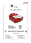
TGGE System
Instruction Manual
Ver. 09/10
Model
Order No.
TGGE System
TGGE System (international)
024-000
024-090
Please read these instructions carefully before using this
apparatus!
Biometra GmbH
Rudolf-Wissell-Str. 30
D-37079 Göttingen
Tel.: ++49 (0)551-50 68 6-0
Fax: ++49 (0)551-50 68 6-66
email: [email protected]
Internet: http://www.biometra.com
Service Department
Rudolf-Wissell-Strasse 14-16
D-37079 Göttingen
Tel.: ++49 (0)551-50 68 6-10 or -12
Fax: ++49 (0)551-50 68 6-11
email: [email protected]
This document describes the state at the time of publishing. It needs not necessarily agree
with future versions.
Subject to change!
TGGE Manual October 2009
2
Contents
1.
Introduction.....................................................................................................................6
1.1
Principle of the method .............................................................................................6
1.2
Field of Applications .................................................................................................6
1.3
Special features ........................................................................................................7
1.3.1
Peltier powered linear temperature gradient.....................................................7
1.3.2
Sensitivity..........................................................................................................8
1.3.3
Patented technology .........................................................................................8
1.4
Technical specifications............................................................................................9
1.5
Legal Notes ............................................................................................................10
1.5.1
Copyright ........................................................................................................10
1.5.2
Liability............................................................................................................10
1.5.3
Meaning of the Instructions.............................................................................10
2.
Safety and Warning Notices ........................................................................................11
2.1
2.2
3.
Installation.....................................................................................................................13
3.1
3.2
3.3
3.4
3.5
3.6
4.
Definition of Symbols ..............................................................................................11
Safety instructions / general remarks .....................................................................11
Content of delivery..................................................................................................13
System Overview....................................................................................................13
Unpack and Check .................................................................................................14
Installation Conditions ............................................................................................14
Operation Voltage...................................................................................................15
Setup ......................................................................................................................15
Considerations for successful TGGE experiments...................................................16
4.1
Design of TGGE experiments.................................................................................17
4.2
Design of DNA fragment for TGGE ........................................................................17
4.2.1
Poland analysis...............................................................................................17
4.2.2
GC clamps ......................................................................................................21
4.2.3
Chemical clamp with Psoralen (Furo[3,2-g]coumarin, C11H6O3) ....................21
4.2.4
Use of SSCP primers......................................................................................22
4.3
Find correct temperature gradient ..........................................................................22
4.4
Parallel analysis of multiple samples ......................................................................23
5.
Sample preparation ......................................................................................................24
5.1
5.2
5.3
6.
Purity of samples ....................................................................................................24
Sample preparation for direct DNA analysis...........................................................24
Denaturation / Renaturation for heteroduplex analysis of DNA ..............................24
Operating.......................................................................................................................25
6.1
Casting of gels ........................................................................................................25
6.1.1
Assembly of the gel cuvette............................................................................25
6.1.2
Preparing gel solution .....................................................................................28
6.2
Pouring gels............................................................................................................29
TGGE Manual October 2009
3
6.3
Electrophoresis with the TGGE System .................................................................29
6.3.1
Electrophoresis conditions..............................................................................30
6.3.2
Conditions for mutation analysis.....................................................................30
6.3.3
Conditions for diversity analysis of bacterial populations (genetic fingerprint)31
6.3.4
Setup electrophoresis unit ..............................................................................31
6.3.5
Prior to assembly of the electrophoresis unit..................................................32
6.3.6
Gel setup for electrophoresis..........................................................................32
6.3.7
Perpendicular TGGE ......................................................................................33
6.3.8
Parallel TGGE.................................................................................................34
6.3.9
Identify optimum temperature gradient ...........................................................34
6.3.10
Calculate temperatures at different lanes .......................................................35
6.4
Programming the TGGE Controller ........................................................................37
6.4.1
Software main menu.......................................................................................37
6.4.2
Create / edit program......................................................................................37
6.4.3
Select program ...............................................................................................37
6.4.4
Name program................................................................................................37
6.4.5
Enter temperatures for the gradient block ......................................................38
6.4.6
Enter electrophoresis parameters...................................................................38
6.4.7
Start electrophoresis.......................................................................................39
6.4.8
Stop/pause electrophoresis ............................................................................40
6.4.9
View temperatures of the gradient..................................................................40
6.5
Special functions ....................................................................................................41
6.5.1
Print programs ................................................................................................41
6.5.2
Select / de-select signal..................................................................................41
6.5.3
Select language ..............................................................................................41
7.
Staining TGGE Gels .....................................................................................................42
7.1
7.2
7.3
7.4
8.
Silver staining protocol ...........................................................................................42
Ethidium bromide-staining ......................................................................................43
Autoradiography .....................................................................................................43
Elution of DNA from the TGGE gel .........................................................................43
Trouble shooting guide................................................................................................44
8.1
Error messages ......................................................................................................45
8.2
Optimization of parallel TGGE ................................................................................46
8.3
Optimization of TGGE for genetic fingerprinting of microorganisms.......................46
8.4
Optimisation of Heteroduplex analysis ...................................................................47
8.5
Evaluation of a heteroduplex analysis ....................................................................48
8.6
TGGE Testkit (024-050) .........................................................................................49
8.6.1
Perpendicular TGGE using the Biometra TGGE test kit .................................49
8.6.2
Parallel TGGE using the Biometra TGGE Test kit ..........................................50
8.6.3
Gel pictures TGGE Test kit.............................................................................50
9.
Maintenance and repair ...............................................................................................51
9.1
9.2
9.3
10.
10.1
Cleaning and Maintenance .....................................................................................51
Servicing and repair................................................................................................51
Replacement of Spare Parts ..................................................................................51
Accessories ..............................................................................................................52
Consumables and spare parts................................................................................52
TGGE Manual October 2009
4
11.
11.1
Service.......................................................................................................................53
Instructions for return shipment ..............................................................................53
12.
Equipment Decontamination Certificate ................................................................54
13.
Note for the disposal of electric / electronic waste...............................................56
14.
EU – Konformitätserklärung, EU - Declaration of Conformity..............................57
15.
Warranty ....................................................................................................................58
16.
Appendix ...................................................................................................................59
16.1 References .............................................................................................................59
16.2 Buffers ....................................................................................................................62
16.2.1
Running buffers: .............................................................................................62
16.2.2
Loading buffers: ..............................................................................................62
16.3 Other buffers:..........................................................................................................63
17.
Subject Index ............................................................................................................64
TGGE Manual October 2009
5
1. Introduction
Temperature Gradient Gel Electrophoresis is a powerful technique for the separation of
nucleic acids or proteins. The TGGE method, which is covered by patents, uses the
temperature dependent changes of conformation for separating molecules.
Since the introduction of the first commercial available TGGE apparatus in 1989,
temperature gradient gel electrophoresis has gained high interest in scientific and clinical
research laboratories due to the unprecedented resolution capability and easiness of
analysis. The range of scientific publications using the TGGE method is broad and covers all
disciplines which use molecular biology methods: e.g. oncology, virology, immunology, RNA
viroid research, prion research, population analysis. The TGGE method has also been used
for quantitative analysis in industry and for conformational analysis of proteins.
1.1 Principle of the method
Conventional protein or nucleic acid electrophoresis separates molecules according to their
size or charge. TGGE adds a new parameter for separation, namely the melting behaviour
of a molecule. The melting behaviour is determined by primary sequence and secondary
and tertiary structure of the molecule and can be changed by external influences like
temperature, salt concentration, pH etc.
During electrophoresis the sample migrates along a temperature gradient. As the
temperature rises the molecules start to denature. Working with PCR fragments for example
electrophoresis starts with double stranded molecules. At a certain temperature the DNA
starts to melt, resulting in a fork-like structure (partial single strand, see Figure 1). In this
conformation the migration is slowed down compared to a completely double stranded DNA
fragment (of same size). Since the melting temperature strongly depends on the base
sequence, DNA fragments of same size but different sequence can be separated. This is
used in mutation detection where PCR fragments of identical size but different sequence are
separated. Thus TGGE not only separates molecules but gives additional information about
melting behaviour and stability.
electrophoresis
cold
ds DNA
partial ss
ss DNA
warm
Figure 1: Different conformations of DNA during temperature gradient gel electrophoresis.
1.2 Field of Applications
The Biometra TGGE system separates molecules in a temperature gradient. Unlike chemical
gradients the peltier driven temperature gradient is controlled by a microprocessor and thus
is providing unmatched reproducibility. The most common application for TGGE is mutation
analysis of PCR fragments. The DNA molecules become separated in the temperature
TGGE Manual October 2009
6
gradient their melting behavior. With TGGE PCR fragments that only have single base
substitutions can be resolved. But, the TGGE system is not restricted to the analysis of DNA
fragments only. It can be used for versatile applications like:
• Mutation analysis
• Heteroduplex analysis
• DNA methylation studies (Imprinting)
• Differentiation of amplicon and competitor for quantitative DNA analyses
• Fidelity assay for thermostable polymerases
• Secondary structure analysis of RNA
• Analysis of dsRNA molecules
• Thermal stability analysis of proteins
• Protein/protein or protein/ligand interaction analysis
1.3 Special features
1.3.1
Peltier powered linear temperature gradient
The heart of the TGGE system is the temperature block which is powered by peltier
technology. Thanks to precise microprocessor control a linear temperature gradient is
generated providing maximum reproducibility. Thus assay conditions can be much better
controlled compared to conventional chemical gradients (DGGE) or temporal gradients using
water baths.
The Biometra TGGE system is available in two formats. The standard TGGE “mini” system
operates small gels and is therefore ideally suited for fast, serial experiments. The TGGE
MAXI system provides a large separation distance and allows high parallel sample
throughput.
Using the Biometra TGGE system it is very easy to separate samples either parallel or
perpendicular to a temperature gradient. All that has to be changed is the position of the
buffer tanks. Whereas perpendicular TGGE is mainly used for the optimization of separation
conditions, parallel TGGE allows fast analysis of multiple samples.
perpendicular TGGE
Temperature gradient is perpendicular to the electrophoretic
migration:
One sample is separated over a broad temperature range to
determine the optimum temperature gradient or to analyze
temperature dependent changes in conformation
Parallel TGGE
Temperature gradient is parallel to electrophoretic migration:
multiple samples are separated in parallel
TGGE Manual October 2009
7
Figure 2: Typical results after perpendicular TGGE (A: temperature gradient from left to right) and parallel TGGE
(B: temperature gradient from top to bottom).
1.3.2
Sensitivity
Because of the small amount of material used for separation, DNA or RNA fragments appear
as fine bands which can be clearly distinguished from each other. Even complex band
patterns can be analyzed due to the high resolution capability of the gradient block.
Comparing the TGGE method with other screening methods like SSCP the superior
performance of the TGGE method becomes evident.
In contrast to direct sequencing TGGE also detects mutations in mixed DNA samples.
Whenever heterozygous DNA is to be analyzed, direct sequencing will not give a clear signal
at the position of the mutation. This is especially the case if the mutated gene is masked by a
high background of normal cells. TGGE reliably detects mutations in a 1:10 dilution (and
higher) of wildtype DNA.
1.3.3
Patented technology
TGGE is protected by patents in most countries of the world. The patent for the TGGE
method is held by Qiagen AG, Hilden. Biometra is the exclusive licensee for manufacturing
and distribution of TGGE instrumentation.
TGGE Manual October 2009
8
1.4 Technical specifications
TGGE System
Electrophoresis unit
Temperature gradient
formation
Block size
Temperature range
Linear temperature
gradient
Temperature accuracy
Temperature uniformity
Glass plates
Gel size
Max. separation distance
Electrophoresis unit with temperature gradient block and two removable
buffer chambers, power supply, starter kit.
High performance Peltier technology
9 x 9 cm
5 – 80 °C
maximum 45 °C
+ 0.3 °C
+ 0.5 °C
9 x 9 cm
approx. 7,8 x 4,2 cm
Perpendicular 4 cm
Parallel 5 cm
Sample number (volume) 10 (5µl)
12 (3µl)
18 (1,5µl)
Dimensions (DxWxH)
23 x 23 x 23 cm
Weight
4,2 kg
Display
Interfaces
Voltage
Microprocessor driven control of temperature gradient and electrophoretic
parameters
31 x 22 x 12 cm
3,8 kg
up to 100 programs can be stored
constant Voltage
V/h integration
Programs can contain different steps (pre-run, pause, run)
LCD display, 4 lines, English / German
parallel (Centronics), serial (RS 232)
110 / 230 V
Power pack
Voltage
Current
Wattage
Control
Dimensions (DxWxH)
Weight
Integrated
maximum 400 V
maximum 500 mA
maximum 30 W
Constant Voltage
-
TGGE System
Controller
Dimensions (DxWxH)
Weight
Program stores
Program modes
TGGE Manual October 2009
9
1.5 Legal Notes
1.5.1
Copyright
All rights reserved. It is not allowed to copy and publish the manual or parts of it in any form
as copies, micro film or other methods without a written authorisation from Biometra.
Biometra is pointing out that applied company and brand names are usually protected trade
marks.
The TGGE method is covered by patents issued to Diagen (now QIAGEN GmbH).
The polymerase chain reaction (PCR) process is covered by patents issued to Hoffman-La
Roche.
Acryl-GlideTM is a trademark of Amresco Inc.
Biometra is a trademark of Biometra GmbH.
The POLAND software service established by Gerhard Steger, Department of Biophysics,
University of Duesseldorf, is available by internet:
www.biophys.uni-duesseldorf.de/POLAND/poland.html
1.5.2
Liability
Biometra is not liable for damages and injuries caused by use not considering these
operating instructions in parts or completely.
1.5.3
Meaning of the Instructions
Biometra recommends that you first read these instructions carefully. This operation
instruction is part of the product and should be kept over the full life-time of the instrument. It
should also be forwarded to subsequent owners and users. Make sure that additions and
updates are inserted into the operation instructions.
TGGE Manual October 2009
10
2.
Safety and Warning Notices
2.1 Definition of Symbols
Symbol
Definition
Caution! Refer to instruction manual!
Danger! High voltage!
Fragile!
Danger! Hot surface!
2.2 Safety instructions / general remarks
The thermoblock will reach high temperatures during operation. The
thermoblock can burn you.
The TGGE system contains no user serviceable parts. Do not open
the housing instrument. Service and repair may only be carried out
by the Biometra Service department or otherwise qualified technical
personal.
Do not use the instrument when damages of the housing, block,
cable or other parts are visible.
Prior to connecting the unit to the power source please ensure that
the voltage setting at the fuse holder at backside of the power supply
is set to the required voltage.
Unplug the power cable before you open the TGGE system. Danger
of electric shock!
The thermoblock is covered with Teflon film. Avoid damaging this
film.
Make sure that the appliance connector and the plug of the supply
cord are accessible, so you can separate the instrument from the
mains.
Connect the TGGE system to a grounded socket.
Appropriate safety regulations must be observed when working with
infectious, pathogenic or radioactive material. Ask the responsible
local safety inspector for details.
TGGE Manual October 2009
11
Place the TGGE system on a stable, non flammable surface in a dry,
safe environment.
Ensure that both the ventilation slits of the TGGE block not clogged
by dust or other material. Danger of overheating!
Do not fill buffer chambers above marking for maximum level
Do not move instrument during operation
In case of strong condensation under the safety lid stop run, dry
instrument and re-start
If buffer has been spilled on the electrophoresis unit, clean it
carefully before start of electrophoresis
Do not use paraffin oil or kerosene on the thermoblock.
Switch off power before removing the safety lid
This instrument is designed and certified to meet EN 61010-1 safety
standards. It should not be modified or altered in any way. Alteration
of this instrument will void the warranty, void the EN61010-1
certification, and create a potential safety hazard.
Do not use alcohol (e.g. methanol, ethanol), organic solvents or
abrasives to clean the instrument.
TGGE Manual October 2009
12
3. Installation
3.1 Content of delivery
1)
Electrophoresis unit
including thermoblock, buffer chambers, safety lid
2)
Controller incl. power supply
control of electrophoresis parameters (Voltage) and temperature gradient
3)
Starter Kit
Glass plates, sealings, cover films, polybond films, buffer wicks, binder clips, sample
Acryl GlideTM* (*only in Germany)
4)
Manual
Please keep the original packaging material for return shipment in case of servicing.
TGGE System, 230/115 V
electrophoresis unit with high precision gradient block, 2 buffer chambers for
variable positioning, controller with integrated power supply, manual, starter
kit 024-003
024-000
TGGE System, 230/115 V
electrophoresis unit with high precision gradient block, 2 buffer chambers for
variable positioning, controller with integrated power supply, manual, starter
kit 024-093
024-090
3.2 System Overview
The TGGE System contains all components necessary to get started. All kinds of TGGE
applications (parallel or perpendicular TGGE, Constant Temperature GE, Time resolved
TGGE) can be run with the Biometra TGGE System. A broad range of different glass plates
are available and can be ordered from Biometra or your local distributor (see section 10).
TGGE Manual October 2009
13
Safety lid
Buffer c hambers
Elec trophoresis unit
c ontroller c ord plug
Figure 3: TGGE Electrophoresis unit
3.3 Unpack and Check
Unpack and carefully examine the instrument. Report any damage to Biometra. Do not
attempt to operate this device if physical damage is present.
Please keep the original packing material for return shipment in case of service issues
!! Attention !!
Please fill out and send back the warranty registration card. This is important for you
to claim full warranty.
3.4 Installation Conditions
•
Place the TGGE system on a stable surface in a dry, safe environment.
•
Let equilibrate the TGGE system to room temperature before starting operation.
•
Make sure that the appliance connector and the plug of the supply cord are accessible,
so you can separate the instrument from the mains.
•
Connect the TGGE system to a grounded socket.
TGGE Manual October 2009
14
Ensure that the ventilation slits at the electrophoresis unit
are unobstructed.
Insufficient ventilation can cause overheating of the
instrument.
Prior to connecting the unit to the power source please ensure that the
voltage selector at the back side of the power supply is set to the
required voltage.
Danger of electric shock! Unplug the power cable before you open the
TGGE system.
3.5 Operation Voltage
Important: Prior to connecting the TGGE system to the mains, make sure that the voltage
setting of the power supply is in accordance with your mains voltage. The set operating
voltage is displayed in the small window of the fuse holder at the backside of the power
supply.
The TGGE system can operate at 110 or 230 Volt. To change operation voltage of the TGGE
system, switch off the instrument and disconnect the mains plug. Press the two clips both
ends of the fuse holder and excerpt it. Pull out the cream coloured insert from the fuse holder
and turn it by 180°. Insert it again and control the voltage displayed in the small window of
the fuse holder. If the setting is correct insert the fuse holder to the power supply again.
Figure 4: TGGE system fuse holder
3.6 Setup
1) Connect electrophoresis unit and controller.
2) Connect power cables from the safety lid to the controller
The buffer chambers can be placed in two orientations, depending on the direction of the
temperature gradient. Be sure that the orientation is correct. The markings on the gradient
block (L0 to L6) indicate the direction of the temperature gradient. The direction of
electrophoresis (minus to plus for nucleic acids) is indicated on the safety lid.
TGGE Manual October 2009
15
4. Considerations for successful TGGE experiments
TGGE is a powerful technique to separate molecules of same size, but different sequence.
Nevertheless, every DNA fragment has its own characteristics and three steps have to be
taken before successful analysis of multiple samples in parallel TGGE can begin. Each of the
following steps is described in detail in this section.
Step 1 Check the sequence of your PCR fragment in Poland analysis. The Poland computer
program (http://www.biophys.uni-duesseldorf.de/POLAND/poland.html) calculates the
melting behavior of dsDNA molecules. Poland analysis can predict, whether a fragment is
suited for TGGE or not. Analysis is available online and free of charge (see section 1.5.1).
Melting profile is ok
Poland analysis shows
a satisfying profile.
Proceed with step 2
Melting profile is not ok
If Poland analysis shows that the fragment in its current
state is not suited for TGGE, optimize your primer design.
Never try to separate samples in TGGE if the calculated
melting profile is not ok. Back to step 1
Step 2 If the Poland analysis shows a suitable melting profile you should test separation
conditions in a perpendicular TGGE. In perpendicular TGGE, a large aliquot of the sample
runs over a broad temperature range. The result of parallel TGGE allows identification of the
temperature gradient for parallel analysis.
Perpendicular gel is
ok
Perpendicular TGGE
shows a nice melting
curve.
Proceed with step 3
Perpendicular gel is not ok
If perpendicular analysis does not show the expected
melting profile, check sequence again in Poland analysis.
Also check purity of chemicals and electrophoretic
conditions.
Do not try samples is parallel TGGE, as long as the
perpendicular gel does not show a defined melting curve.
Back to step 2
Step 3 Set up a parallel gel with the temperature gradient derived from the perpendicular gel.
Separation can be optimized by varying the temperature gradient and voltage.
TGGE Manual October 2009
16
4.1 Design of TGGE experiments
There are 3 steps in the setup of a new TGGE experiment:
1) Design of the PCR fragment
2) Identification of the correct temperature gradient
3) Parallel analysis of multiple samples
4.2 Design of DNA fragment for TGGE
The design of the DNA fragment is an important step for successful TGGE. Starting with the
gene fragment of interest PCR primers should be designed with a conventional computer
program. The melting behavior of the resulting fragment should then be checked with the
Poland software. It is essential that the DNA fragment shows different melting domains. If
there is only one single melting domain, an artificial higher melting domain (called GC clamp)
must be added during PCR.
4.2.1
Poland analysis
The melting profile of a DNA fragment can be analyzed with a computer program. The
Poland software calculates the melting behaviour of a DNA fragment according to its base
sequence. This software is free accessible via the internet.
(http://www.biophys.uni-duesseldorf.de/POLAND/poland.html).
How to perform a Poland analysis
•
Open start page (URL see above)
•
1) enter a name for the query
•
2) copy / paste DNA sequence in the sequence window
•
3) choose the Tm plot (de-activate all other plots)
•
4) submit query
•
5) retrieve Tm plot (melting curve)
TGGE Manual October 2009
17
Poland service request form
The Poland server will calculate the thermal denaturation profile of double-stranded RNA,
DNA or RNA/DNA-hybrids based on sequence input and parameter settings in this form.
NEW: Thermodynamic parameters set for dsDNA in 75 mM NaCl (Blake & Delcourt) added.
Calculation is based on Poland's algorithm in the implementation described by Steger.
Graphics results are directly sent to your WWW client.
1)
Sequence title line:
TGGE Manual October 2009
18
2)
Sequence:
(plain format;
no numbers;
max. 1000 nts;
min. 5 nts)
Mismatched positions:
(comma-separated numbers)
Thermodynamic parameters:
Dissociation constant ß:
TGGE Manual October 2009
Oligonucleotide
(ß is function of seq.length)
Long double strand
(default: ß=1.0E-3/M)
19
Strand concentration:
(default: 1.0E-6 M)
High temperature Temperature
Low temperature limit:
limit: (default: 110.0 step size:
(default: 40.0 °C)
°C)
(default: 2.0 °C)
Temperature range:
3)
Tm(p=50%) plot 3d plot Mobility plot
Which graphics do you want:
Melting
curve
Diff.
melting
curve
Graphics size:
(GIF format)
4)
submit
Click here to
, or
Zurücksetzen
Click here to
the form to defaults.
The Tm plot (second order, red color) shows the melting profile of the DNA fragment
according to the base sequence. The ideal fragment shows at least two distinct melting
domains. Note that mutations can be detected in all but the highest melting domain. This
means that in a DNA fragment with two melting domains, mutations can only be detected in
the lower melting domain.
Figure 5: Tm plot of a 140bp DNA fragment resulting from Poland analysis. The second order curve (red color in
the original) shows two different melting domains.
If the fragment consists of a single melting domain only, or if you want to scan the entire
fragment for mutations, add a so called GC clamp to one end of the PCR fragment.
TGGE Manual October 2009
20
4.2.2
GC clamps
A GC clamp is an artificial, high melting domain which is attached to one end of the fragment
during PCR. The name “GC clamp” implies that this short stretch will hold the DNA fragment
together, preventing a dissociation into the single strands at higher temperatures. The
optimum location for the GC clamp at the PCR fragment (5´ or 3´) can be easily checked with
the Poland software. Copy / paste the GC sequence to either side of your sequence and
repeat Poland analysis. In the following box you will find different examples for a GC clamp.
short GC-clamp (23 bp):
cccgc cgcgc cccgc cgccc gcc
long GC-clamp (40 bp)44:
cgccc gccgc gcccc gcgcc cggcc cgccg ccccc gcccg
long GC-camp (39 bp)45:
ccccg ccccc gccgc ccccc ccgcg cccgg cgccc ccgc
To integrate a GC clamp into a PCR fragment, one of the two primers has to be modified.
The non-specific GC sequence is added to the 5´-end of the primer. Thus the GC sequence
is incorporated in the fragment during PCR. Prior to order primers check the melting
behaviour of the PCR fragment with GC clamp by Poland analysis (see chapter 4.2.1).
Figure 6 shows a Tm plot for a PCR fragment with GC clamp either at the 5’-or 3’-end.
GC-clamp at 5´end
GC-clamp at 3´end
bubble
Figure 6: Tm-Plot of a PCR fragment with GC clamp at the 5’-end or at the 3’-end. Whereas the fragment with 5’GC clamp has domains that melt consecutively and is well suited for TGGE analysis the fragment with 3’-GC
clamp has a domain in the middle that melts at lower temperature compared to the neighbouring domains and is
therefore leading to bubble formation. Thus the 3’-GC clamp for this fragment will not work for TGGE analysis.
4.2.3
Chemical clamp with Psoralen (Furo[3,2-g]coumarin, C11H6O3)
In addition to “clamping” a fragment with an artificial high melting domain it is as well possible
to covalently fix the end of a PCR fragment. To achieve this, one of the primers carries a
Psoralen molecule. Psoralen is a high reactive group when exposed to UV radiation. Thus it
is possible to covalently close one end of the PCR fragment. The optimal primer sequence
may be 5’(Pso)pTaPpnpnp.....3’, given the preference of Psoralen for binding between TpA
and ApT pairs 13,46,47. Crosslinking of the PCR product is done e.g. in a flat-bottom
microtiter plate using a 365 nm UV source. Working with small volumes it may be necessary
to minimize evaporation by cross-linking at 4 – 10°C. The yield is not affected by
TGGE Manual October 2009
21
temperature. The distance of the sample from the UV source affects the yield. 15 min at 0.5
cm distance of the sample from an 8 W UV lamp is sufficient.
4.2.4
Use of SSCP primers
In many cases primer from SSCP may be used for TGGE analysis. Nevertheless, the
resulting DNA fragments should be checked in the Poland analysis. If there is only one
melting domain add a GC clamp to one of the primers (see section 4.2.2)
4.3 Find correct temperature gradient
Poland analysis gives the first indication, which temperature gradient should be applied for
parallel analysis of multiple samples. Under experimental conditions separation is performed
in the presence of high concentrations of urea. Urea lowers the melting temperature of the
DNA. This is important because gel electrophoresis at very high temperatures may lead to
partial drying of the gel, resulting in a disturbed separation pattern. Therefore it is necessary
to identify the optimum temperature gradient under experimental conditions.
To identify the optimum temperature gradient the DNA fragment is separated in a
perpendicular TGGE. This means the temperature gradient is perpendicular to the migration
of samples (see section 6.3.7). Thus the migration of a fragment can be checked
simultaneously at different temperatures in a single run. If the PCR fragment has been
designed properly the separation in a perpendicular temperature gradient leads to a distinct
melting curve (see Figure 7)
Figure 7: Identification of the optimum temperature gradient in a perpendicular TGGE. At low temperature (below
T1) DNA migrates as a double strand (left side). At intermediate temperature (between T1 and T2) the DNA
opens at one side, the partial double strand is increasingly slowed down. Above T2 the DNA separates into the
single strands.
At T1 the double strand starts to melt and forms a branched structure. At T2 the partial
double strand separates irreversibly into the single strands. Analysis of samples in parallel
TGGE should be performed precisely in this temperature range between T1 and T2.
How to identify the optimum temperature range from a perpendicular gel:
Place the stained gel on the plastic film with the printed lines (l0 to L6). Identify the line where
the double strand starts to melt (T1) and the line where the double strands separates into the
single strands (T2). For the calculation of temperature at the corresponding lines see section
6.3.10.
TGGE Manual October 2009
22
4.4 Parallel analysis of multiple samples
electrophoresis
After identification of T1 and T2 in a perpendicular TGGE this temperature gradient is spread
over the whole block for parallel analysis.
cold
warm
T1
T2
Figure 8: Application of T1 and T2 in a parallel gel.
Note: The DNA fragments are separated by their melting behavior. They can be
distinguished as soon as the fragments begin to melt, i.e. they form a fork like structure
(temperature higher than T1). During electrophoresis the fragments should not separate into
single strands. This is an irreversible transition resulting in diffuse bands.
Note: If there are only small differences in the migration of different samples, perform a
heteroduplex analysis (see chapter 8.4)
TGGE Manual October 2009
23
5. Sample preparation
5.1 Purity of samples
Due to the high sensitivity of the staining procedure after TGGE it is recommended to use
purified DNA, RNA or protein samples. Any impurities might be misinterpreted after TGGE,
thereby making the analysis of gels difficult. Nevertheless it is possible to use even crude
mixtures for TGGE analysis.
PCR-amplified DNA fragments usually can be analyzed without further purification. Please
note that the presence of high amounts of nonspecific, secondary PCR products may result
in difficulties with interpretation of band pattern, melting profile, etc. For example, in parallel
TGGE, nonspecific bands with a higher molecular weight than the specific PCR product may
be misinterpreted as heteroduplices, or analogs with lower thermal stabilities. Therefore,
prior to TGGE check the PCR product in a conventional agarose gel. If necessary, purify
your specific PCR product, e.g., by agarose gel electrophoresis and subsequent gel
extraction.
5.2 Sample preparation for direct DNA analysis
1 volume of DNA/RNA samples is mixed with 1 volume of TBE or Na-TAE loading buffer or
with 0.1 volume of the total loading volume ME loading buffer (see Appendix). The resulting
mixture is loaded directly on to the polyacrylamid gels. Be sure that the slots are filled up to
maximum (if necessary, add 1x loading buffer to fill up the slots to maximum).
In case of low-concentration samples we recommend to prepare 5x conc. loading buffer. 0.2
volume of this concentrated loading buffer is mixed with 0.8 volumes of the sample and
loaded onto the gel.
5.3 Denaturation / Renaturation for heteroduplex analysis of DNA
Mix sample with equal amount of standard DNA and heat to 95°C for 5 minutes
(denaturation). Then let slowly cool down to 50°C (renaturation). This can be done by
programming a thermocycler to 94°C for 5 minutes and then 50 °C for 15 minutes with a
ramping rate of –0.1°C/second. The sample is then loaded directly to the gel. In order to
achieve the recommended loading volumes for diagonal or perpendicular TGGE, the sample
volume should be adjusted with running buffer.
Important: Do not denature/renature DNA for community profiling (see chapter 6.3.3)!
TGGE Manual October 2009
24
6. Operating
6.1 Casting of gels
6.1.1 Assembly of the gel cuvette
The TGGE system (024-000) contains all components needed for casting custom gels (glass
plates, clamps etc.). There are two different types of gels for TGGE. For perpendicular gels
one long slot is used to separate one sample over a broad temperature range (use glass
plate with slot former, 024-023). For parallel gels samples are applied to single slots (use
glass plate with slot formers, 024-022 or 024-025). The gel cuvette consists of one glass
plate with spacers and slot formers (024-022 or 024-025) and a glass plate without spacers
(024-021). The sandwich is fixed with 3 plastic clamps. The thinness of the polyacrylamide
gel makes it necessary to cast the gel on a gel support film (Polybond film, order number:
024-030). The gel will stay on this film throughout the whole procedure (including silver
stain).
A.
Cover glass plate without spacers (bonding plate)
B.
Polybond film
C.
Glass plate with slot formers and spacers (different types of slots available).
Bonding plate
(024-021)
Glass plate with
slot fomer and spacers
(024-022)
Poybond support film
(024-030)
Figure 9: Components of the TGGE cuvette for casting gels
Note: The gel is poured on Polybond film to optimize temperature transition between block
and gel. The gel is bound covalently to this hydrophilic Polybond film (024-030).
Note: The gel sticks to the Polybond film throughout the whole procedure, including staining.
1)
Glass plates must be dry and free of any dirt or dust. Please wear powder-free
gloves during cleaning and assembly of gel sandwich, to prevent contamination
(which will interfere with silver staining). Clean both glass plates with 70% ethanol and
a soft tissue.
TGGE Manual October 2009
25
Do not use strong acidic or basic solutions or organic solvents for
cleaning the glass plates.
Do not apply mechanical stress on slot formers (i.e. brushing or
rubbing)
Do not incubate glass plates over night in cleaning solutions!
2)
The glass plate with spacer and slot former must be carefully treated with a repelling
agent. This is essential for easy removal of the polymerized gel from the glass plate
with slot formers. Apply approx. 0.5 ml of gel repellent solution (Acryl Glide, Amresco
or Repel silane, Sigma) on the glass plate WITH SPACERS and spread it carefully
especially between the slot former. Wait 5 min, than polish the plate with soft
tissue to remove residual solution!
Do not drop repelling solution on the spacers of the glass plate! This
will lead to leakage of the gel cuvette during polymerization.
Do not treat the bonding plate with repelling agent.
3)
Clean spacers with ethanol before assembling the glass plate sandwich.
4)
Apply some silicone grease onto the spacers (to prevent leakage).
Note: Treatment of the glass plate with slot formers should be repeated prior to every use.
5)
Use original pre-cut Polybond support film which perfectly fits onto the gradient block.
Remove protecting paper sheet from polybond film prior to assembly of sandwich.
Handle Polybond film only with powder-free gloves. Attach Polybond film firmly to
the bonding glass plate by gently rubbing with a soft tissue. To improve contact
between glass plate and film a drop of water may be applied behind the Polybond
film.
Note: The Polybond support film has a hydrophilic coating. The gel matrix binds covalently to
the support film. In earlier batches, Polybond film was coated only on one side. Today, both
sides can be used for gel casting, the orientation of the film is not important.
Note: The support film may be fixed along the upper side of the cover glass plate with
ordinary adhesive tape. This way no gel solution can accidentally get behind the support film.
TGGE Manual October 2009
26
Bonding plate
(024-021)
Poybond support film
(024-030)
Glass plate with
slot fomer and spacers
(024-022)
Figure 10: Assembly of the TGGE cuvette for casting gels
6)
Assemble gel sandwich and fix it with the 3 plastic clamps.
Note: the clamps should be placed directly on the spacers.
7)
Set gel sandwich upright to pour the gel.
Clamp
Clamp
Clamp
Figure 11: Final setup of the gel sandwich
Figure 12: Gel casting stand
Note: For convenient casting of 5 gels in parallel we recommend gel casting stand 024-028,
(Figure 12).
TGGE Manual October 2009
27
6.1.2
Preparing gel solution
The choice of the buffer system has a strong impact on TGGE analysis. Concentration of salt
and denaturing agents (urea or formatted) strongly affects the melting temperature of DNA
and proteins. In general, urea is used for the separation of nucleic acids in a concentration
between 7 and 8M. Urea reduces the melting temperature and thus enables a separation at
lower temperatures (which is favorable, because at higher temperatures the gel tends to dry
out). To further reduce the melting temperature (deionized) formamide may be used in
concentrations of up to 20%. The most popular buffer systems for TGGE are TBE, TAE and
MOPS. In the following, two standard protocols for TBE and MOPS buffer systems are listed.
Please note, that the buffer system should be adapted to each special kind of application.
Each gel sandwich contains approx. 2.5 ml polyacrylamide solution. We recommend to
prepare 10 ml solution to pour 3-4 gels at a time. Gels should be used within 24 hours
after polymerization. To prevent gel drying, wrap polymerized gels into saran foil or wet
plastic bags. Wet paper towels may be used for short time storage (1 day).
The below gel composition is intended for mutation analysis with the TGGE test Kit (024050). Gel protocols for other applications can be found in section 6.3.
Polyacrylamide is a toxic substance. Skin contact or inhalation must be
strictly avoided. Wearing laboratory gloves is mandatory during all steps.
Please carefully read the safety sheets of the chemicals prior to use and
behave accordingly.
Protocol for 10 ml gel solution (3 gels)
Volume /
amount
Final
concentration
Urea
4,8 g
8M
40% Acrylamide/Bis-Acrylamide (37,5 : 1)
2 ml
8%
10 x TAE
1 ml
1x
40% Glycerol
500 µl
2%
Adjust with aqua bidest to
10 ml
•
Stir solution at < 50°C until urea is completely dissolved
•
Carefully degas gel solution
•
Let solution cool down to room temperature and start polymerization with
APS (4%)
40 µl
TEMED
9 µl
• Once TEMED and APS have been added, the following steps must be performed without
delay.
• Load gel solution in a syringe and attach a 0,4µm or 0,25µm sterile filter
TGGE Manual October 2009
28
• Pour gel through sterile filter into the glass sandwich.
6.2 Pouring gels
Figure 13: Pouring polyacrylamide gel.
• Hold gel sandwich at an angle of 45° when pouring. The solution should run slowly along
one side of the plate sandwich to avoid air bubbles. Turn gel sandwich into vertical
position.
• Polymerization of gel for 1 - 1.5 h or over night at room temperature. The sandwich should
stand up vertically and must not be moved during polymerization. Overlaying the gel
solution with 2-Butanol will yield an even gel surface after polymerization.
• After polymerization remove clamps. Remove the glass plate without spacers by sliding
the glass plate away from the rest of the sandwich (if you have fixed the support film with
adhesive tape, remove or cut tape first). The gel must stick on the support film.
• Slowly take off the Polybond film with the adhering polyacrylamide gel from the other
glass plate. In the area of the slot former remove the Polybond film very carefully to
avoid any damage to the slots.
• Do only use perfect shaped slots because otherwise the bands will be distorted.
Note: After dissolution of urea batch solution may be stored up to 2 weeks at room
temperature. Remove clamps and wrap gel sandwich including glass plates in wet paper
towels. Store the sandwich in a tight plastic bag. Gels must not be stored at low
temperatures (i.e. refrigerator) because this will lead to precipitation of urea.
Note: Prepare electrophoresis unit prior to disassembling the gel cuvette. The gel should not
be exposed to the air for extended periods since this may lead to drying of the gel.
6.3 Electrophoresis with the TGGE System
Since in TGGE molecules are separated according to their primary sequence, there are
many potential fields of application. For some applications TGGE has become already the
TGGE Manual October 2009
29
method of choice. Currently, there are two major fields: Mutation analysis in PCR fragments
and diversity analysis of complex bacterial samples. The main difference between these
two applications is that in the former case only one or two PCR fragments (mutant and
wildtype) are separated per lane, whereas in the latter case a mixture of many (up to 150)
fragments are separated in one lane. While sample throughput is always an important
aspect, long separation distance is mainly necessary, if many bands are to be separated.
Therefore the TGGE maxi system is the system of choice for diversity analysis, whereas the
TGGE standard system allows short electrophoresis times and provides high serial sample
throughput for mutation analysis.
6.3.1
Electrophoresis conditions
The electrophoresis unit of the TGGE System has been designed to accommodate TGGE
and all related applications like CTGE, TTGE and SSCP without cumbersome changes. In
contrast to conventional electrophoresis techniques like PAGE or agarose gel
electrophoresis the migration behaviour of samples in TGGE depends very strongly on the
temperature gradient. Better separation in TGGE is NOT achieved by longer
electrophoresis times! Once the samples start to melt their migration is almost stopped.
Therefore extended migration times and higher voltage will rather lead to fuzzy bands than to
a better resolution. To improve resolution (i.e. distance between two bands in one lane) the
temperature gradient has to bee adjusted (see section 8.1).
In general migration of samples in TGGE depends on
•
Temperature gradient
•
Buffer system
•
Gel composition
•
Voltage
•
The kind of sample, e.g. protein, nucleic acid, fragment size
•
The kind of application, e.g. parallel or perpendicular TGGE
•
Sample preparation, e.g. high salt or low salt preparation
Any recommendations should be regarded as guidelines to start with. Further improvement
of the analysis should be done by adjusting the run conditions to individual needs.
Important: The TGGE controller is designed to control voltage NOT amperage. [mA] and
[Vh] should be set to maximum.
6.3.2
Conditions for mutation analysis
Since each DNA fragment has its own melting characteristic, there can be no general valid
parameters for mutation analysis. The following parameters have been optimized for
separating the Biometra TGGE test kit DNA (024-050). If other fragments are to be analyzed,
please
optimize
parameters
as
described
in
chapter
4
and
8.
Gel composition: 1 x TAE buffer, 8% Polyacrylamide (37.5:1), 8M Urea, 2% Glycerol
Temperature gradient: L1: 39°C, L6 54°C
Electrophoresis: 250V, 50 min
TGGE Manual October 2009
30
6.3.3
Conditions for diversity analysis of bacterial populations (genetic fingerprint)
For genetic fingerprinting primers against 16SrRNA genes are used. Depending on the
complexity of the sample and the primer design quite a high number of PCR fragments can
arise from one sample. In this regard there are two major differences to mutation analysis: 1)
the number of fragments per lane is much higher 2) the amount of DNA per band is lower. To
separate all the many fragments a rather flat gradient is used which has to be optimized very
carefully. For detecting low amounts of DNA a clear staining background is essential. The
silver staining protocol (chapter .) has been optimized for gels with high content of urea and
formamide and thus achieves high sensitivity at low background.
For microbial diversity analysis we recommend the following conditions. However, these
parameters can only be the starting point for individual optimization.
Gel composition: 1 x TAE buffer, 6% Polyacrylamide (37.5:1), 8M Urea, 2% Glycerol, 20%
Formamide
Temperature gradient: L1: 33°C, L6 44°C
Electrophoresis: 130V, 2h
Important: Do not denature/renature the DNA fragments prior to electrophoresis!
6.3.4
Setup electrophoresis unit
The Biometra TGGE system is a horizontal electrophoresis system. The buffer bridges to the
gel are established by layering one side of each buffer wick (024-003) on the gel and
submerging the other in the buffer inside the tank. To protect the gel from drying, it is
covered with a gel cover film (024-032). The complete setup, consisting of gel with cover film
and buffer wicks, is covered with the gel cover plate. The gel cover plate has two sealings
and fits tightly onto the thermoblock. It holds the buffer wicks in place and helps to build a
humidity chamber around the gel. This is important to prevent evaporation during the run.
Important: Never run a gel without gel cover plate. (This could lead to
massive condensation under the safety lid. Danger of electric shock.)
Gel cover plate
Sample
Figure 14: Set up of the gel for electrophoresis
TGGE Manual October 2009
31
6.3.5
Prior to assembly of the electrophoresis unit
Note: Be sure to have everything on hand, to avoid extended handling times. Do not let the
disassembled gel dry while setting up the electrophoresis system.
Prepare:
•
parallel or perpendicular gel (see section 6.3.7 or section 6.3.8)
•
samples in loading buffer (for sample preparation see chapter 6.4)
•
500 ml 1 x TAE running buffer (chapter 16.2.1)
•
2 buffer wicks (024-003)
•
1 cover film (024-035)
•
thermal coupling solution (0.01% Triton)
•
gel cover plate (024-031)
6.3.6
Gel setup for electrophoresis
1)
Adjust electrophoresis chamber with the 4 levelling feet.
2)
Fill 250 ml running buffer in each buffer tank (check orientation of the buffer tanks:
parallel or perpendicular TGGE, see section 6.3.7 or section 6.3.8).
Note: Wipe off any spilled buffer from the electrophoresis unit. Never run device if buffer
has been spilled.
3)
Soak 2 buffer wicks with running buffer
4)
Disassemble gel sandwich. Clean backside of the gel support film with a soft tissue.
5)
Apply 150µl of thermal coupling solution (0.01% Triton) on the thermoblock
Note: The volume of coupling solution should be as small as possible. Excess coupling
solution leads to an irreproducible temperature distribution under the gel. The result is a
wavelike migration front and poor separation of fragments.
6)
Place the gel on the thermoblock. The thermal coupling solution should spread over
the whole block. Avoid bubbles. Wipe off any residual coupling solution along the
edges of the gel support film.
Note: The thermal coupling solution is essential for efficient heat transfer from block to gel. If
bubbles are trapped under the gel support film, remove support film with gel from the block
and place it back again on the block.
7)
Cover the gel with a cover film. The cover film should be placed just beneath the
slots.
8)
Attach pre-soaked buffer wicks on top and bottom of the gel
TGGE Manual October 2009
32
Cover film
Buffer wick
Gel
Buffer wick
Figure 15: Setup of gel, cover film and buffer wicks.
9)
Load samples (approx. 5µl each for parallel gel with 8 slots, approx. 50µl for
perpendicular gel with 1 slot)
Note: Be careful not to touch the samples with the buffer wick! Otherwise the samples will
quickly diffuse into the wick.
10)
Attach gel cover plate (the cover plate should have contact to the wicks, but should
not squeeze gel or wicks).
11)
Close safety lid and start run.
Note: For parallel TGGE let temperature gradient equilibrate for approx. 10 minutes, then
start main run. This step may be omitted for a perpendicular gel.
6.3.7
Perpendicular TGGE
In perpendicular TGGE one sample is separated over a broad temperature range. This
application is mainly used to check the melting behaviour of a sample (see section 6.3.9).
For casting of the gel use a glass plate with one large slot former (024-023). The temperature
gradient must be orientated perpendicular to the migration of the sample. The buffer tanks
must be positioned as described in Figure 16.
The migration of DNA / RNA molecules is indicated by the arrow on the safety lid of the
electrophoresis unit.
TGGE Manual October 2009
33
Gradient
Electrophoresis
+
Figure 16: Positioning of buffer tanks for perpendicular TGGE. Be sure that the direction of electrophoresis is
perpendicular to the temperature gradient. The temperature gradient is indicated by lines L1 to L6.
6.3.8
Parallel TGGE
In parallel TGGE multiple samples are separated along the temperature gradient. For casting
of the gel use glass plate with 8, 12 or 18 slots (024-022, -025 or -026). The buffer tanks for
parallel TGGE must be positioned as depicted in Figure 17.
-
Gradient
Elec trophoresis
+
Figure 17: Positioning of buffer tanks for parallel TGGE. Be sure that the direction of electrophoresis is parallel to
the temperature gradient. The slots of the gel should be at the same side as the markings on the block.
6.3.9
Identify optimum temperature gradient
Poland analysis gives the first indication, which temperature gradient should be applied for
parallel analysis of multiple samples. In real life, electrophoresis is performed in the presence
TGGE Manual October 2009
34
of high concentrations of denaturing agents (urea and Formamide). Both lower the melting
temperature of the DNA fragment. This allows electrophoresis at lower temperatures
preventing partial drying effects in the gel, resulting in a disturbed separation pattern.
Therefore it is necessary to identify the optimum temperature gradient under experimental
conditions.
To identify the optimum temperature gradient the DNA fragment is separated in a
perpendicular TGGE. This means the temperature gradient is perpendicular to the migration
direction (see section 6.3.7). Thus the migration of one sample can be checked
simultaneously at different temperatures in a single run. If the PCR fragment has been
designed properly the separation in a perpendicular temperature gradient leads to a distinct
melting curve (see Figure 18)
Figure 18: Identification of the optimum temperature gradient in a perpendicular TGGE. At low temperature (below
T1) DNA migrates as a double strand (left side). At intermediate temperature (between T1 and T2) the DNA
opens at one side, the partial double strand is increasingly slowed down. Above T2 the DNA separates into the
single strands.
At T1 the double strand starts to melt and forms a branched structure. At T2 the partial
double strand separates irreversibly into the single strands. Analysis of samples in parallel
TGGE should be performed precisely in this temperature range between T1 and T2.
6.3.10 Calculate temperatures at different lanes
Place the stained perpendicular gel on the TGGE thermo block showing lanes L1 to L6.
Identify at what lane the double strand starts to melt (T1) and at what lane the double strands
separates into the single strands (T2).
TGGE Manual October 2009
35
The calculation of the corresponding temperatures is simple, since there is a linear
temperature gradient between L1 and L6 (i.e. the temperature increment from one to the next
line is always the same).
Calculation: Divide range of gradient by five (L6 – L1), this is the temperature increment
from one line to the adjacent lane.
Example:
calculation of temperature at line 2,5 in a temperature gradient from 40°C (L1)
to 60°C (L6)
•
subtract temperature at L1 from temperature L6 (range of gradient: 60-40°C = 20°C)
•
divide temperature by 5 (increment per lane: 20°C/5 = 4°C)
•
multiply increment by 1,5 (1,5 increments from L1 to L2,5 = 6°C)
•
add this value to the temperature at L1 (40°C + 6°C)
Result:
temperature at L 2,5 is 46°C
TGGE Manual October 2009
36
6.4 Programming the TGGE Controller
All parameters of the run are controlled by the TGGE system controller. This includes
electrophoretic parameters (voltage, amperage, time) as well as control of the temperature
gradient. After switching on the controller the display shows the instruments name and
software version. Then the main menu appears.
Note: Each program can consist of several steps. Thus you can program pre-run,
equilibration and main run in the same program.
6.4.1
Software main menu
T1: 22.0°C
T2: 22.0°C
At the bottom line the display shows 4 options which
can be activated by the 4 functions keys ªA, B, C, D.
Block off
A?
B Elpho
C programs D +
These 4 options change during programming, relative
to the chosen menu.
A “?”:
retrieve comments or tips about the current program step
B “Elpho”:
commands to open and start a program
C “programs”:
edit existing or create new programs
D “+”:
further options like printing of programs or protocols, choice of
language, selecting signal
6.4.2
Create / edit program
Press C [programs] to enter the programming mode
Program no:
Alist Bdel Cquit Denter
6.4.3
Select program
Enter a program directly by number or press A [list] to view a list of the existing programs.
0 test 1
1 parallel
2 empty
AÏ BÐ C quit D enter
Scroll through the list with AÏ BÐ and accept highlighted program with D [enter].
6.4.4
Name program
Each program is specified by name and a program number. To facilitate retrieval of a
program, you can enter a name for each program existing of letters, numbers and symbols.
name:>
<
TGGE Manual October 2009
37
ABCDEFGHIJKLMNOPQRST
UVWXYZ –()αδ/,〈〉&+.%
AÎ BABC C quit D enter
Press B [ABC] to enter the mode for the selection of letters.
name:>
<
ABCDEFGHIJKLMNOPQRST
UVWXYZ –()αδ/,〈〉&+.%
AÍ BÎ C quit D enter
Move to the desired letter with A [Í] and B [Î]. Accept highlighted letter with D [enter].
name:>test
<
ABCDEFGHIJKLMNOPQRST
UVWXYZ –()αδ/,〈〉&+.%
AÍ BÎ C quit D enter
If the program name is complete, confirm name with D [enter]. In the following screen you
can set the temperatures for the gradient block.
6.4.5
Enter temperatures for the gradient block
1:L0:
L6:
A? B
C quit D Î
Enter temperature for L0 and accept with D [enter].
1:L0:30.0
L6:
A? Bdelete Cquit Denter
Enter temperature for L6 and accept with D [enter].
1:L0: 30.0
L6: 70.0
ok?
A B no C quit D yes
Confirm settings with D [yes]. If settings are not correct press B [no] and repeat entry of
temperature settings.
After you have confirmed the temperature settings, the following screen is displayed. Here
you can enter all parameters for electrophoresis.
6.4.6
Enter electrophoresis parameters
1:L0: 25.0 L6: 60.0
time:
El: 0V 500mA 30W
A? B V*h C quit D Î
Enter time for electrophoresis and accept with D [enter].
TGGE Manual October 2009
38
Note: There is a convention on how time settings are entered in all BIOMETRA instruments:
hours z minutes z seconds
If you enter a number without “dot” this value will be interpreted as seconds (“300” => 5
minutes). To program minutes enter a “z” after the number of minutes. To enter hours enter z
z after the number. You can also enter any combination of hours, minutes and seconds.
Example: for 1 hour, 30 minutes, 20 seconds enter 1z 30 z 20.
The time values will be displayed in the following format: 00 m 00s
Accept time setting with [D enter]
1:L0: 25.0 L6: 60.0
time: 10m 0s
El: 0V 500mA 30W
A? Bdelete C quit D enter
Enter Voltage and accept with D [enter]
1:L0: 25.0 L6: 60.0
time: 10m 0s
El: 250V 500mA 30W
A? Bdelete C quit D enter
Note: The values for amperage [mA] and wattage [W] are set to maximum level as default. If
you enter lower values, these parameters may become limiting during electrophoresis.
Accept default settings for voltage and wattage with D [enter] or enter different values.
Note: We recommend to control electrophoresis by constant voltage rather than by constant
amperage (set [mA] to maximum value, respectively accept default value).
Note: Each program can consist of several steps. Thus it is possible to program complex
protocols including a pre-run, a pause for handling of the gel and the main run..
In the following screen you can program a second step for your protocol.
2:L0:
A? B
L6:
C quit D Î
If you do not want to program another step, accept program with C [quit].
The program name, number of steps and the total run time is displayed.
program no. 8
pgm end: 1 step(s)
run time: 0h10m 0s
A? B
C quit D Î
6.4.7
Start electrophoresis
Main screen:
L0: 20.0°C L6: 20.0°C
block off
A? BElpho Cprograms D+
To start a program press B [Elpho]
TGGE Manual October 2009
39
start program:
Alist Bdel Cquit Denter
Enter program number or choose a program from the list with A [list].
start program: 8
Alist Bdel Cquit Denter
Confirm program number with D [enter].
The program starts and parameters of gradient block and electrophoresis are displayed.
During temperature equilibration of the gradient block the elapsed time is displayed.
Note: Electrophoresis starts as soon as the set temperature in the block is achieved.
L0: 25.0°C L6: 60.0°C
hold: 1 2m12s 11.4Vh
El: 250V 8mA 20.3W
A? BElpho Cprograms D+
6.4.8
Stop/pause electrophoresis
L0: 25.0°C L6: 60.0°C
hold: 1 2m12s 11.4Vh
El: 250V 8mA 20.3W
A? BElpho Cprograms D+
To stop/pause the active program press B [Elpho]
program 8 test
pause ?
stop ?
A? Bpause Cquit Dstop
Press B [pause] to pause program
Press D [stop] to stop program
Press C [quit] to return to the active program.
6.4.9
View temperatures of the gradient
L0: 20.0°C L6: 65.0°C
hold: 1 2m12s 11.4Vh
El: 150V 8mA 20.3W
A? BElpho Cprograms D+
To display the temperatures in the block during a run press A [?]:
T1: 21.1°C T2: 63.8°C
L1→3: 21.1 32.0
39.0
L3→6: 46.0 53.0
60.0
← = const
rtime: h m
The actual temperatures of T1 and T2 as well as the actual temperatures of L1 to L6 are
TGGE Manual October 2009
40
displayed. The limiting factor (const. V, mA or W) is indicated by a blinking arrow (←). The
actual remaining electrophoresis time is shown.
6.5 Special functions
Main screen
L0: 20.0°C L6: 20.0°C
block off
A? BElpho Cprograms D+
Press D [+] to enter the menu for special functions
1 print programs
2 signal
3 language
4 standard mode
5 test mode
6 void
not occupied
not occupied
not occupied
AÏ BÐ C quit D enter
Scroll through the list with AÏ BÐ.
6.5.1
Print programs
Connect controller to a dot matrix printer. Select option 1 in the above menu and confirm with
D [enter].
6.5.2
Select / de-select signal
Select option 2 in the special functions. Press A [on] to activate the signal, press B [off] to
inactivate signal.
6.5.3
Select language
Select option 3 in the special function screen. Choose between German and English
TGGE Manual October 2009
41
7. Staining TGGE Gels
Aside from autoradiography silver staining is the most sensitive method for detecting small
amounts of DNA, RNA or proteins in polyacrylamide gels. Other staining protocols may be
used, but generally exhibit less sensitivity. This must be considered in relation to the amount
of DNA loaded on the gel.
All incubation steps are done in small plastic containers which are agitated on a rocking
platform (e.g. order number 042-400 or 042-500).
Wear non-powdered protective gloves during all steps of the silver staining protocol
to avoid staining artifacts due to the high sensitivity of the staining protocol.
The quality of chemicals is essential in silver staining. Prepare solutions fresh, use
only chemicals of high quality (p.a.) and fresh double distilled water.
Important: Remove the protective plastic sheets from the gel.
•
Carefully remove residual thermal coupling solution from the back of the gel (gel support
film) prior to staining.
•
Put the polyacrylamide gel with the gel side upwards into the staining tray. Avoid air
bubbles during all staining steps.
•
It’s recommended to prepare at least 100 ml solution for each incubation step.
•
Prepare stopping solution prior to developing.
7.1 Silver staining protocol
Step
Time
Solution
Fixation
30 min
100 ml
10% glacial acid, 30% EtOH
Sensitization
2 x 10 min
100 ml
30% EtOH
Washing
Rinse gel 30 seconds
under running water,
Silver Binding
then wash 5 x 5 min
Fresh aqua dest
30 min
100ml 0,1 % AgNO3, prepare freshly
add 350µl Formaldehyde (37%) prior to use
Washing
Developing
Rinse 30 seconds
then wash 1 min
Rinse again 30 seconds
Fresh aqua dest.
Until bands become visible, Solution 1: dissolve 0,2g Sodium thiosulfate
(Na2S2O3) in 10ml bidest,
which can take several
minutes,
Solution 2: dissolve 2,5g Sodium Carbonate
(Na2CO3) in 100ml bidest
don’t let gel unattended!
Add 100µl solution 1 to solution 2
Add 350µl Formaldehyde (37%)
TGGE Manual October 2009
42
Stopping
discard developer
Stop solution: 100 ml 10% glacial acid
add stop solution
incubate for 30 min
Storage
Up to several days at room 10% Glycerol
temperature
Long term
storage
Remove gel from 10%
glycerol and let it dry.
The gel will dry completely to the gel support
film and can then be stored indefinitely.
7.2 Ethidium bromide-staining
Incubate the gel in staining solution (0.5 μg/ml ethidium bromide in 1 X TAE) for 30 - 45 min.
Analyze under UV radiation (27).
Note: The TGGE gel must be positioned face down on the UV table. Otherwise the support
film will shield bands from excitation by UV light.
7.3 Autoradiography
TGGE gels can also be directly exposed to x-ray films if radiolabeled samples are analyzed.
Direct exposure:
Incubate the TGGE gel for 15 min. in Fixation solution (see 6.5 Silver staining). Optional:
Silver stain the gel.
Remove residual buffer from the gel. Expose to an x-ray film at room temperature.
Exposure of dried TGGE gels:
Incubate the TGGE gel for 15 min. in Fixation solution (see 6.5 Silver staining). Optional:
Silver stain the gel.
Incubate the gel in 2-5% glycerol for 10 minutes to prevent the gel from cracking. Incubate an
appropriate sheet of cellophane (no Saran wrap!!!!!) in 2 - 5% glycerol. Layer the cellophane
on the gel. Air dry at room temperature for one day or use a gel dryer at 50°C for at least 3h.
Expose to an X-ray film.
7.4 Elution of DNA from the TGGE gel
DNA fragments which have been separated on TGGE, for example, different alleles of one
gene, can be eluted from silver-stained TGGE gel and re-amplified by PCR.
Using a Pasteur pipette, puncture the gel and extract a μl piece containing the particular DNA
duplex. Incubate in 20 μl TE buffer overnight. Use a 1 μl aliquot for re-amplification.
TGGE Manual October 2009
43
8. Trouble shooting guide
The following trouble-shooting guide may be helpful in solving any problem that you may
encounter. If you need further assistance, please do not hesitate to contact your local
Biometra distributor or Biometra.
Problem
Cause
Solution
Inaccurate positioning of
sealing
Check positioning of silicone sealing,
Electrophoresis
Leakage of gel cuvette
clean Spacer,
Dust on spacers
Acryl glide on spacers
do not apply Acryl Glide onto the
spacers
Support film is not properly
attached to the glass plate
Fix polybond film with adhesive tape
along the upper edge of the glass
plate
Block has been cleaned with
strong detergents or
aggressive chemicals
Contact Biometra
Amperage and Wattage
have been set to “0”
Set Amperage and Wattage to
maximum values (Electrophoresis
should be controlled by Voltage)
Coating of the thermoblock
is damaged, the safety
shutoff is activated
Contact Biometra
Wavelike migration front
Temperature inhomogeneity
under the gel due to excess
thermal coupling solution
Use as little as possible thermal
coupling solution (not more than 2ml)
No sigmoid melting curve
(perpendicular TGGE)
Fragment melts completely
Perform Poland analysis
Acrylamide solution gets
behind the support film during
pouring the gel
Teflon film peels away from
the thermoblock
No current
Current oscillates
Gel interpretation
Optimize primer design
No separation of hetero duplex
Inappropriate fragment
samples
Wrong temperature gradient
(parallel TGGE)
Acrylamide of poor quality
Irreproducible gels
Perform Poland analysis
Perform perpendicular TGGE
Use only high quality chemicals (p.a.)
Erratic temperature
distribution over and under
the gel
Use only minimum volume of thermal
coupling solution under the gel
Chemicals of poor quality
Use only high quality chemicals
Stale water
Use only freshly prepared aqua bidest
Too much silver nitrate
Refer to the staining protocol
Do not overlay gel with buffer
Silver staining
Bad silver stain
TGGE Manual October 2009
44
Strong background
Weak staining of bands
Insufficient washing after
incubation in staining
solution
Extend wash step, change water
frequently
Excessive washing after
binding of staining solution
Reduce wash step after staining
8.1 Error messages
TGGE connector cable is not connected to gradient block and / or
TGGE - System
check connection
System Controller.
Check connections!
to thermoblock
Warning:
Invalid gradient temperatures (maximum gradient 45°C).
Gradient too large!
max. grad. T1→T2: 45°C
A ? B no→L1 C quit D enter
Or
Invalid gradient temperatures (maximum gradient 45°C).
Warning:
Gradient too large!
max. grad. T1→T2: 45°C
A ? B no→T1 C quit D enter
It is possible to review a program during run. After pressing ªC
Program no:
TEST
Program name and store is displayed
Pgm is active!
A copy B del C quit D display
Program no: __
This program number has not been programmed.
Name:
not programmed!
A↑
B↓
C quit
1:L1: __
D enter
L6:
No temperature or time settings.
entry required
T1:
A?
T2:
B L1
C quit
D→
Or
1:L1: __
L6:
No temperature or time settings
entry required
T1: __
T2:
A ? B T1
C quit D →
TGGE Manual October 2009
45
8.2 Optimization of parallel TGGE
To improve separation in parallel TGGE the gradient should start directly at the temperature
where the fragments start to melt (see perpendicular gel) and should be rather flat. This
means there should be only a moderate temperature increase over the whole gel. Different
fragments in one sample separate as soon as the first fragment starts to melt. At a certain
(higher) temperature the next fragment starts to melt. In a moderate gradient, the
temperature increase per centimeter is smaller than in a steeper gradient. This means, the
distance between two temperatures (i.e. locations in the gel) is bigger than in a steeper
temperature gradient. This results in a wider separation of fragments that melt at different
temperatures (see Figure 19).
A
30°C
70°C
B
30°C
40°C
Figure 19: Parallel TGGE using a steep (A) or a flat (B) temperature gradient. With a smaller temperature gradient
(30 to 40 °C, B) the separation of samples is much wider. (Note: the temperatures in this Figure are only for
demonstration.)
8.3 Optimization of TGGE for genetic fingerprinting of
microorganisms
Primers should be designed thoroughly to avoid unspecific PCR products. Ideally sequences
of the species considered must be compared for identifying conserved regions. Further, the
PCR cycles should be reduced to a minimum while extension times should be enlarged to
avoid the formation of heteroduplex artefacts. In cases of mixed-template PCR products a
low cycler number reamplification may increase specificity. In general, PCR products should
be purified prior to TGGE analysis. Sometimes PCR artefacts are co-amplified which can
result in smears on TGGE gels. PCR products can be purified by PCR purification kits or
ideally each PCR-product is subjected to conventional agarose electrophoresis. After
TGGE Manual October 2009
46
electrophoretic separation, for each sample the desired band can be cut from the gel and
purified.
8.4 Optimisation of Heteroduplex analysis
If the difference in melting temperature between wildtype and mutant is very small,
heteroduplex analysis is a rewarding approach. Heteroduplex analysis makes it very easy to
distinguish between the wildtype and mutant form of a DNA fragment. The basic principle is
to mix each sample with an external standard. In most cases this standard is a PCR
fragment without mutations, for example amplified from the wild type. After mixing the
standard DNA fragment with the PCR fragment from the sample the mixture is heated and
subsequently slowly cooled down (for protocol see section 5.3).
a
a
A
a
A
a
a
A
A
a
A
A
denature
re-anneal
Figure 20: Principle of heteroduplex analysis. The re-annealing of sample and standard results in 4 different DNA
fragments. 1) The wildtype homoduplex (AA), 2) the mutant homoduplex (aa), 3) and 4) two different
heteroduplices (Aa and aA). These heteroduplices carry at least one mismatch (disturbed base pairing) and have
a significant lower melting temperature than the homoduplices.
This procedure results in a complete denaturing of both double stranded PCR fragments and
a subsequent re-annealing. If the sample is different from the standard, re-annealing leads to
4 different double stranded DNA fragments (see Figure 20): 1) the homoduplex of the
standard (wildtype AA), 2) the homoduplex of the sample (mutant aa),3) and 4) two
heteroduplices between standard and sample (Aa and aA). Due to the differences between
sample and standard these heteroduplices display mismatches in their base pairing in least
one position. Such mismatches have a strong impact on the melting behavior because the
number of base pairs between the two strands is reduced. Therefore the heteroduplices can
be easily separated from the homoduplices using TGGE.
The identification of the optimum temperature gradient for the separation of a heteroduplex
analysis is absolutely the same as for a single fragment. The separation of a heteroduplex
sample in a perpendicular TGGE results in 4 different melting curves. The 2 heteroduplices
have a lower melting temperature and denature at a lower temperature compared to the
homoduplices.
TGGE Manual October 2009
47
electrophoresis
heteroduplex Aa
heteroduplex aA
homoduplex aa
homoduplex AA
cold
warm
Figure 21: Separation of a heteroduplex sample in perpendicular TGGE.
The temperature gradient can then be adapted in the same way as for a conventional sample
(see chapter 6.3.9). In parallel TGGE, the samples melt as they migrate along the
temperature gradient. The heteroduplices (with mismatch) melt at a lower temperature than
the homoduplices. Thus they open earlier in the partial single strand and are slowed down in
the gel matrix. The homoduplices migrate a longer distance as complete double strands and
start to melt at a higher temperature (i.e. later in respect to the temperature gradient).
Therefore the lower bands in parallel TGGE are the homoduplices, whereas the higher
bands are the heteroduplices.
Figure 22: Schematic drawing of a screening multiple samples in a parallel TGGE. Both homoduplices (AA, aa)
have a higher melting temperature and migrate further in the gel. The heteroduplices melt at a lower temperature
resulting in a slower migration.
8.5 Evaluation of a heteroduplex analysis
There are two possible states in heteroduplex analysis: 1) the sample is identical to the
standard (wildtype) 2) the sample is different from the wildtype. In the former case, the
denaturation / renaturation procedure results in one (the same) homoduplex. The
subsequent separation in parallel TGGE shows only a single band. In the latter case,
denaturation / renaturation leads to the four different populations. Separation in parallel
TGGE therefore results in up to four different bands (see 8.6.3). If the temperature gradient
has not been correctly optimized, or if separation time was to short, there may as well only
be two or three bands.
TGGE Manual October 2009
48
This makes heteroduplex analysis very easy to evaluate:
number of bands
result
one
sample is identical to the standard
no mutation
more than one (up to 4
bands)
sample is different form the standard
mutation
8.6 TGGE Testkit (024-050)
The TGGE test kit was developed to get familiar with the TGGE system. It contains 3 tubes
with different DNA samples and 1 tube with loading buffer.
wild type DNA
homoduplex
40 µl
Mutant DNA
homoduplex
40 µl
Mutant / wildtype DNA
heteroduplex
400 µl
Loading buffer
1 ml
Prior to use, samples should to be diluted in 1x TAE running buffer.
The samples are separated in an 8% PAA gel with 8M Urea and a 1 x TAE buffer system
(for preparation of gel solution and buffer see section 9.
8.6.1
Perpendicular TGGE using the Biometra TGGE test kit
1) sample preparation
mix 25 µl heteroduplex sample with
25 µl loading buffer TAE (see section 16.2.2)
2) Vortex, quick spin and load 50 µl in the broad slot of a perpendicular gel
3) Let sample migrate into the gel with 250V for approx. 7 minutes
4) Cover gel with cover film, assemble buffer wicks, cover plate and safety lid
5) start run
Temperature gradient
30 to 70°C
Voltage:
250V
Run time:
40 min
6) silver stain gel
TGGE Manual October 2009
49
8.6.2
Parallel TGGE using the Biometra TGGE Test kit
1) sample preparation:
mix 2.5µl sample (wildtype or mutant or heteroduplex) with
2.5µl loading buffer (TAE) (see section 16.2.2)
2) Assemble electrophoresis unit, cover gel with cover film (beneath the slots), assemble
cover plate and safety lid
3) Vortex, quick spin and load 5 µl of wildtype, mutant and heteroduplex samples
4) Let sample migrate into the gel with 250V for approx. 7 minutes
5) After pre-run, cover gel like described in section 6.3.4
6) start main run
Temperature gradient
30 to 60 °C
Voltage:
250V
Run time:
50 min
7) silver stain gel
8.6.3
Gel pictures TGGE Test kit
perpendicular TGGE
TGGE Manual October 2009
parallel TGGE
50
9.
Maintenance and repair
9.1 Cleaning and Maintenance
The TGGE system is built to operate for a long time without the need for periodical
maintenance. Nevertheless, occasionally cleaning of the air inlet may be necessary to
maintain the efficiency of the thermoblock. The inlet for the airflow is located at sides of the
themoblock. Be sure that the inlet is not clogged by dust or other materials. Dust can be
removed easily from the inlet with a conventional vacuum cleaner. Additionally, the housing
may be cleaned from time to time with a smooth cotton cloth. Do not use strong detergents,
abrasives or organic solvents for cleaning.
Important: Appropriate safety regulations must be observed when working with infectious or
pathogenic material.
9.2 Servicing and repair
The TGGE system contains no user serviceable parts. Do not open the housing instrument.
Service and repair may only be carried out by the Biometra Service department or otherwise
qualified technical personal.
9.3 Replacement of Spare Parts
Only original spare parts mentioned in these operating instructions are allowed.
TGGE Manual October 2009
51
10. Accessories
10.1 Consumables and spare parts
TGGE Starter Kit (Germany only)
024-003
1 glass plate 1 slot (024-023), 1 glass plate 8 slots (024-022), 1 glass plate
12 slots (024-025), 3 bonding plates (024-021), 4 electrode wicks (024-016),
25 Polybond films (024-030), Acryl Glide™ sample (211-319), 3 plastic
clamps (010-007)
TGGE Starter Kit (International)
024-093
1 glass plate 1 slot (024-023), 1 glass plate 8 slots (024-022), 1 glass plate
12 slots (024-025), 3 bonding plates (024-021), 4 electrode wicks (024-016),
25 Polybond films (024-030), 3 plastic clamps (010-007)
TGGE buffer wicks 8 x 7 cm, 100 pcs.
024-015
Electrode wicks reusable, 4 pcs.
024-016
TGGE glass plate 9 x 9cm, without spacer
024-021
TGGE glass plate 9 x 9cm, 8 slots 5µl, 0.5mm spacer
024-022
TGGE glass plate 9 x 9cm, 1 slot 50µl, 0.5mm spacer
024-023
TGGE glass plate 9 x 9cm, 1 diagonal slot 75µl, 0.5mm spacer
024-024
TGGE glass plate 9 x 9cm, 12 slots 3µl, 0.5mm spacer
024-025
TGGE glass plate 9 x 9cm, 18 slots 1-2µl, 0.5mm spacer
024-026
TGGE glass plate 9 x 9cm, without slot, 0.5mm spacer
024-027
TGGE Polybond Film, 8.8 x 8.8cm, 25 pcs.
024-030
TGGE Polybond Film, 8.8 x 8.8cm, 100 pcs.
024-034
TGGE cover glass plate with silicon sealings, incl. 10 cover films 7 x 6cm
024-031
TGGE cover films 7 x 6 cm, 25 pcs.
024-032
TGGE cover films 7 x 6 cm, 100 pcs.
024-035
TGGE Test Kit
40µl wildtype DNA, 40µl mutant DNA, 400µl heteroduplex DNA, 1ml loading
buffer, manual
024-050
TGGE gel casting stand for 5 gel sandwiches 9 x 9cm
024-028
TGGE Manual October 2009
52
11. Service
Should you have any problems with this unit, please contact our service department or your
local Biometra dealer:
Biometra GmbH
Service Department
Rudolf-Wissell-Straße 14 - 16
D-37079 Göttingen
Phone:++49 (0)5 51 50 68 6 - 10 or 12
Fax: ++49 (0)5 51 50 68 6 -11
e-mail: [email protected]
If you would like to send the unit back to us, please read the following return
instructions in chapter 11.1.
11.1 Instructions for return shipment
In case of an instrument failure that cannot be fixed by the procedures described in section 8
please proceed as follows:
•
•
•
•
•
Return only defective devices. For technical problems which are not definitively
recognisable as device faults please contact the Technical Service Department at
Biometra (Tel.: +49 551-50881-10/12, Fax: +49 551-50881-11, e-mail:
[email protected]).
Please contact our service department for providing a return authorization number
(RAN). This number has to be applied clearly visible to the outer box. Returns without
the RAN will be not be accepted!
Important: Carefully clean all parts of the instrument of biologically dangerous, chemical or
radioactive contaminants. If an instrument is contaminated, Biometra will be forced to
refuse to accept the device. The sender of the repair order will be held liable for possible
losses resulting from insufficient decontamination of the device.
Please prepare written confirmation that the device is free from biologically dangerous and
radioactive contaminants. The declaration of decontamination (see section 12) must be
attached to the outside of the packaging.
Use the original packing material. If not available, contact Biometra or your local
distributor.
•
Label the outside of the box with “CAUTION! SENSITIVE ELECTRONIC INSTRUMENT!”
•
Please enclose a note which contains the following:
a)
Sender’s name and address,
b)
Name of a contact person for further inquiries with telephone number,
c)
Description of the fault, which also reveals during which procedures the fault
occurred, if possible
TGGE Manual October 2009
53
12. Equipment Decontamination Certificate
To enable us to comply with german law (i.e. §71 StrlSchV, §17 GefStoffV and §19 ChemG)
and to avoid exposure to hazardous materials during handling or repair, please complete this
form, prior to the equipment leaving your laboratory.
COMPANY / INSTITUTE
__________________________________________________
ADDRESS
______________________________________________________________
PHONE NO
_________________________
E-MAIL
______________________________________________________________
EQUIPMENT
FAX NO_________________________
Model
______________
Serial No
______________
______________
______________
______________
______________
______________
______________
If on loan / evaluation Start Date: __________________
Finish Date __________________
Hazardous materials used with this equipment:
__________________________________________________________________________
__________________________________________________________________________
__________________________________________________________________________
Method of cleaning / decontamination:
__________________________________________________________________________
__________________________________________________________________________
__________________________________________________________________________
The equipment has been cleaned and decontaminated:
NAME __________________________________ POSITION _______________________
(HEAD OF DIV./ DEP./ INSTITUTE / COMPANY)
SIGNED ________________________________ DATE ____________________________
PLEASE RETURN THIS FORM TO BIOMETRA GMBH OR YOUR LOCAL BIOMETRA
DISTRIBUTOR TOGETHER WITH THE EQUIPMENT.
TGGE Manual October 2009
54
PLEASE ATTACH THIS CERTIFICATE OUTSIDE THE PACKAGING. INSTRUMENTS
WITHOUT THIS CERTIFICATE ATTACHED WILL BE RETURNED TO SENDER.
General Information for Decontamination:
Please contact your responsible health & safety officer for details.
Use of radioactive substances:
Please contact your responsible person for details.
Use of genetically change organism or parts of those:
Please contact your responsible person for details.
TGGE Manual October 2009
55
13. Note for the disposal of electric / electronic waste.
Note
for disposal of electric / electronic waste
Hinweis
für die Entsorgung von Elektroaltgeräten
Renseignement
du traitement des déchets des appareils
électrique / électronique
This symbol (the crossed-out wheelie bin) means, that this product should be brought to the return and / or
separate systems available to end-users according to yours country regulations, when this product has reached
the end of its lifetime.
For details, please contact your local distributor!
This symbol applies only to the countries within the EEA*.
EEA = European Economics Area, comprising all EU-members plus Norway, Iceland and Liechtenstein.
-------------------------------------------------------------------------------------------------------------------------------------------------------
Dieses Symbol (die durchgestrichene Abfalltonne) bedeutet, dass dieses Produkt von der Firma Biometra
für eine kostenlose Entsorgung zurückgenommen wird. Dies gilt nur für Geräte, die innerhalb
Deutschlands gekauft worden sind.
Kontaktieren Sie für die Entsorgung bitte die Biometra Service-Abteilung!
Außerhalb Deutschlands wenden Sie sich bitte an den lokalen Händler.
Dieses Symbol gilt nur in Staaten des EWR*.
*EWR = Europäischer Wirtschaftsraum, umfasst die EU-Mitgliedsstaaten sowie Norwegen, Island und
Liechtenstein.
-------------------------------------------------------------------------------------------------------------------------------------------------------
Cet symbol (conteneur à déchets barré d´une croix) signifie que le produit, en fin de vie, doit être retourné
à un des systèmes de collecte mis à la disposition des utilisateurs finaux en conséquence des
régulations par la loi de votre pays.
Pour des information additionel nous Vous demandons de contacter votre distributeur!
Cet symbole s´ápplique uniquement aux pays de l´EEE*.
EEE = Espace économique européen, qui regroupe les États membres de l´UE et la Norvège, Islande et le
Liechtenstein.
TGGE Manual October 2009
56
14. EU – Konformitätserklärung, EU - Declaration of
Conformity
Göttingen, den 01.10.1997
im Sinne der EG-Richtlinie über elektrische Betriebsmittel zur Verwendung innerhalb
bestimmter Spannungsgrenzen 73/23/EWG, Anhang III
following the EC directive about electrical equipment for use within certain limits of voltage
73/23/EWG, appendix 3
und / and
im Sinne der EG-Richtlinie für die elektromagnetische Verträglichkeit 89/336/EWG, Anhang I.
following the EC directive about theelectromagnetic compability 89/336/EWG, appendix 1.
Hiermit erklären wir, daß folgende Elektrophoresegeräte:
Herewith we declare that the following gel electrophoresis systems:
Typen:
TGGE-System,
TGGE Stromversorgungsgerät mit integriertem Controller,
TGGE Elektrophoreseeinheit mit Peltier-Element,
TGGE Pufferkammer
types:
TGGE system,
TGGE power supply with integrated controller,
TGGE electrophoresis unit with Peltier element-powered gradient block,
TGGE electrophoresis chamber
Best.-Nr. / Order No.: 024-000, 024-001, 024-002, 020-010, 024-090, 024-091, 024-092
den grundlegenden Anforderungen der
corresponds to the basic requirements of
EG-Niederspannungsrichtlinie 73/23 EWG i.d.F. 93/68 EWG und der
EC low voltage directive 73/23 EWG in version 93/68 EWG and the
EG-Richtlinie über die elektromagnetische Verträglichkeit 89/336 EWG i.d.F. 93/68 EWG
entsprechen.
EC directive about the electromagnetic compatibility 89/336/EWG in version 93/68 EWG.
Folgende harmonisierte Normen wurden angewandt:
The following harmonized standards have been used:
EN 50081-1
EN 60555-2
EN 61010-1
EN 50082-1
EN 60555-3
EN 61010-2
....................................................
Quality Manager: Dr. Jürgen Otte
TGGE Manual October 2009
57
15. Warranty
This Biometra instrument has been carefully build, inspected and quality controlled before
dispatch. Hereby Biometra warrants that this instrument conforms to the specifications given
in this manual. This warranty covers defects in materials or workmanship as described under
the following conditions:
This warranty is valid for 24 month from date of shipment to the customer from Biometra.
This warranty will not be extended to a third party without a written agreement of Biometra.
This warranty covers only the instrument and all original accessories delivered with the
instrument. This warranty is valid only if the instrument is operated as described in the
manual.
Biometra will repair or replace each part which is returned and found to be defective. This
warranty does not apply to wear from normal use, failure to follow operating instructions,
negligence or to parts altered or abused.
TGGE Manual October 2009
58
16. Appendix
16.1 References
Note: To get an updated overview of all publications available on TGGE, please go to the
website of Medline (http://www.ncbi.nlm.nih.gov/PubMed/) and enter the keyword "TGGE".
1. Riesner, D., Henco, K. and Steger, G. (1990): Temperature-Gradient Gel Electrophoresis: A method
for the analysis of conformational transitions and mutations in nucleic acids and protein. Page
169-250 In Chrambach, A., Dunn, M.J., Radola, B.J.: Advances in Electrophoresis, Vol. 4, VCH
Verlagsgesellschaft Weinheim
2. Kappes, S. et al.(1995): p53 mutations in ovarian tumors, detected by temperature-gradient gel
electrophoresis, direct sequencing and immunohistochemistry. Int. J. Cancer 64: 52-59
3. Milde-Langosch, K. et al. (1995): Presence and persistence of HPV and p53 mutation in cancer of
the cervix uteri and the vulva. Int. J. Cancer 63: 639-645
4. Horn, D. et al.(1996): Three novel mutations of the NF1 gene detected by temperature gradient gel
electrophoresis of exons 5 and 8. Electrophoresis 17: 1559-1563
5. Wieland, U. et al.(1996): Quantification of HIV-1 proviral DNA and analysis of genomic diversity b
ypolymerase chain reaction and temperature gradient gel electrophoresis. J. Virology Methods
57: 127-139
6. Kuhn, J.E. et al. (1995): Quantitation of human cytomegalovirus genomes in the brain of AIDS
patients. Journal of Medical Virology 47: 70-82
7. Linke, B. et. al. (1995): Identification and structural analysis of rearranged immunoglobulin heavy
chain genes in lymphomas and leukemia. Leukemia 9: 840-847.
8. Menke M.A. et al. (1995): Temperature gradient gel electrophoresis for analysis of a polymerase
chain reaction-based diagnostic clonality assay in the early stages of cutaneous T-cell
lymphomas.
9. Hecker, R. et al. (1988): Analysis of RNA structure by temperature-gradient gel electrophoresis:
viroid replication and processing. Gene 72: 59-74
10. Baumstark, T. and Riesner, D. (1995): Only one of four possible secondary structures of the
central conserved region of potato spindle tuber viroid is a substrate for processing in a potato
nuclear extract. Nucleid Acids Research 23: 4246-4254
11. Loss, P., Schmitz, M., Steger, G. and Riesner, D. (1991): Formation of a thermodynamically
metastable structure containing hairpin II is critical for the potato spindle tuber viroid. EMBO
Journal 10: 719-728
12. Riesner, D. (1998): Nucleic acid structures. In: Antisense Technology. Practical Approach Series.
Oxford University Press. p1-24 (in press)
13. Wiese, U. et al. (1995): Scanning for mutations in the human prion protein open reading frame by
temporal temperature gradient gel electrophoresis. Electrophoresis 16: 1851-1860
14. Nubel, U. et al. (1996): Sequence heterogenities of genes encoding 16S rRNAs in Paenibacillus
polymyxa detected by temperature gradient gel electrophoresis.
TGGE Manual October 2009
59
15. Lessa, E.P. and Applebaum, G. (1993): Screening techniques for detecting allelic variation in DNA
sequences. Molecular Ecology 2: 119-129
16. Richter, A., Plobner, L., Schumacher, J. 1997: Quantitatives PCR-Verfahren zur Bestimmung der
Plasmidkopienzahl in rekombinanten Expressionssystemen. BIOforum 20: 545-547
17. Henco, K. and Heibey, M. (1990): Quantitative PCR – the determination of template copy numbers
by temperature gradient gel electrophoresis. Nucleic Acids Research 18: 6733-6734
18. Birmes, A. et al. (1990): Analysis of the conformational transition of proteins by temperaturegradient gel electrophoresis. Electrophoresis 11: 795-801
19. Arakawa, T. et al. (1993): Analysis of the heat-induced denaturation of proteins using temperature
gradient gel electrophoresis. Analytical Biochemistry 208: 255-259
20. Chen, X. et al. (1995): High resolution SSCP by optimization of the temperature by transverse
TGGE. Nucleic Acids Research 23: 4524-4525
21. Scholz, R.B. et al. (1993): Rapid screening for Tp53 mutations by temperature gradient gel
electrophoresis: a comparison with SSCP analysis. Human Molecular Genetics 2: 2155-2158
22. Elphinstone and Baverstock, P.R. (1997): Detecting mitochondrial genotypes by temperature
gradient gel electrophoresis and heteroduplex analysis. BioTechniques 23: 982-986
23. Poland, D. (1974): Recursion relation generation of probability profiles for sequence-specific
macromolecules with long-range correlations. Biopolymers 13:1859-1871
24. Lerman, L.S. and Silverstein, K. (1987): Computational simulation of DNA-melting and its
application to denaturing gradient-gel electrophoresis. Meth. Enzymol. 155: 482-501
25. Steger, G. (1994): Thermal denaturation of double-stranded nucleic acids: prediction of
temperatures critical for gradient electrophoresis and polymerase chain reaction.
26. Schumacher, J, Randels, J.W. and Riesner,D. (1983): A two dimensional electrophoretic
technique for detection of circular viroids and virusoids. Anal. Biochem. 135, 288 - 295
27. Sambrook, J., Fritsch, E.F. and Maniatis,T. (1989): Molecular cloning, Cold Spring Habor
Laboratory press
28. Steger, G. and Riesner, D. (1992): Temperaturgradienten-Gelelektrophorese: eine Methode zur
Analyse von Konformationsübergängen und Mutationen in Nukleinsäuren und Proteinen. In
Radola, B.J. (ed) Handbuch der elektrophorese, VCH Verlagsgesellschaft, Weinheim
29. Sheffield, V.C., Cox, D.R. and Lerman, R.M. (1989): Attachment of a 40-base-pair G+C-rich
sequence (GC-clamp) to genomic DNA fragments by the polymerase chain reactiob results in
improved detection of single-base changes. Proc. Natl. Acad. Sci. USA 86, 232 - 236
30. Hecker R., Wang Z., Steger G. and Riesner D. (1988): Analysis of RNA structure by temperaturegradient gel electrophoresis: viroid replication and processing. Gene 72, 59-74
31. Jiang L., Chen W., Tain L.P. and Liu Y. (1991): Temperature-gradient gel electrophoresis of apple
scar skin viroid. Acta Microbiol. Sin. 30, 278-283
32. Riesner D., Hecker R. and Steger G. (1988): Structure of viroid replication intermediates as
studied by thermodynamics and temperature-gradient gel electrophoresis. In Sarma R.H. and
Sarma M.H. (eds.) Structure & Expression, Vol. I: From Proteins to Ribosomes, Adenine press,
261-285
TGGE Manual October 2009
60
33. Riesner D., Steger G., Zimmat R., Owens R.A., Wagenhöfer M., Hillen W., Vollbach S. and Henco
K. (1989): Temperature-gradient gel electrophoresis of nuleic acids: Analysis of confor-mational
transitions, sequence variations, and protein-nucleic acid interactions. Electrophoresis 10, 377389
34. Rosenbaum V. and Riesner D. (1987): Temperature-gradient gel electrophoresis: thermodynamic
analysis of nucleic acids and proteins in purified form and in cellular extract. Biohys. Chem. 26,
235-246
35. Schönborn J., Oberstraß J., Breyel E., Tittgen J., Schumacher J., Lukacs N. (1991): Monoclonall
antibodies to double-stranded RNA as probes of RNA structure in crude nucleic acid extracts.
Nucleic Acids Res. 19, 2993-3000
36. Po Tien, Steger G., Rosenbaum V., Kaper J. and Riesner D. (1987): Double-stranded
cucumovirus associated RNA5: experimental analysis of nec-rogenic and non-necrogenic
variants by temperature-gradient gel electrophoresis. Nucleic Acids Res. 15, 5069-5083
37. Zimmat R., Gruner R., Hecker R., Steger G. and Riesner D. (1991): Analysis of mutations in viroid
RNA by non-denaturing and temperature-gradient gel electrophoresis. In R.H. Sarma and M.H.
Sarma (eds.) Structure & Methods, Vol. 3:, DNA & RNA, Adenine Press, 339-357
38. Rosenbaum V., Klahn T., Lundberg Holmgren E., von Gabain A. and Riesner D. (1992): Coexisting structures of an mRNA stability determinat: The 5‘ region of the Escherichia coli and
Serratia marcescens ompA mRNA, J.Mol.Biol., in press
39. Birmes A., Sättler A., Maurer S.O. and Riesner D. (1990): „Analysis of the conformational
transitions of proteins by temperature-gradient gel electrophoresis“. Electrophoresis 11, 795801
40. Sättler A., Kanka S., Schrörs W. and Riesner D. (1992): „Random mutagenesis of the weak
calcium binding side in SubtilisinCarlsberg and screening for thermal stability by temperaturegradient gel electrophoresis“. Accepted for: 1st International Symposium of Subtilisin Enzymes,
EMBL, Hamburg
41. Thatcher D. and Hodson B. (1981): „Denaturation of proteins and nucleic acids by thermalgradient electrophoresis“. Biochem. J. 197, 105-109
42. Wagenhöfer M., Hansen D. and Hillen W. (1988): „Thermal denaturation of engineered tet
repressor proteins and their complexes with tet operator and tetracycline studie by temperaturegradient gel electrophoresis“. Analytical Biochem. 175, 422-432
43. Sanguinetti C.J., Neto E.D. and Simpson A.J.G. (1994): BioTechniques 17, 915
44. Kappes, S., Milde-Langosch, K., Kressin, P., Passlack, B., Dockhorn-Dwornczak,
B., Röhlke, P. and Löning, T. (1995): "p53 Mutations in ovarian tumors, detected by temperaturegradient gel electrophoresis, direct sequencing and immunohistochemistry". Int. J. Cancer 64,
52 - 59
45. Kluwe, L., MacCollin, M., Tatagiba, M., Thomas, S., Hazim, W., Haase, W. and
Mautner, V.-F. (1998): "Phenotypic variability associated with 14 splice-site mutations in the NF2
gene". American Journal of Medical Genetics 77, 228 - 233
46. Lerman, L. S. and Beldjord, C. (1998). "Comprehensive mutation detection with
denaturing gradient gel electrophoresis". In R.G.H. Cotton, E. Edkins and S. Forrest (eds.) Mutation
Detection, A Practical Approach, Oxford University Press, 35 - 62
47. Gamper, H., Piette, J. and Hearst, J.E. (1984): Photochem. Photobiol. 40, 29 ff
TGGE Manual October 2009
61
16.2 Buffers
16.2.1 Running buffers:
TBE Running buffer 0.1 x conc. TBE (up to 1x conc. TBE is possible)
10 x TBE (stock solution)
890 mM Boric Acid
20 mM EDTA
890 mM TRIS
Do not titrate to adjust pH!
TAE Running Buffer 1 x conc. TAE, pH 8.0
50 x TAE (stock solution)
(10 x conc.)
pH 8.0
MOPS-Running Buffer
50x MOPS (stock solution)
MOPS/EDTA (ME)
(50 x conc.)
242g Tris base (2M)
57,1 ml glacial acid
100ml 0.5M EDTA (pH 8.0)
1 x conc. MOPS
1M MOPS
50 mM EDTA
pH = 8.0
16.2.2 Loading buffers:
Loading buffer TBE
TBE running buffer
0.1% Triton-X 100
0.01% Bromophenol Blue dye
0.01% Xylene Cyanol dye
Loading buffer TAE
TGGE Manual October 2009
TAE running buffer
0.1% Triton-X 100
0.01% Bromophenol Blue dye
0.01% Xylene Cyanol dye
2 mM EDTA
62
Loading buffer MOPS
MOPS running buffer
1 mM EDTA
0.05% Bromophenol Blue dye
0.05% Xylene Cyanol dye
pH = 8.0
16.3 Other buffers:
TE buffer
10 mM Tris/HCl
0.1 mM EDTA
pH = 8.0
TEMED
Solution of N,N,N’,N’tetramethylethylendiamine
APS
10% Ammonium persulfate
Glycerol 40%
40% glycerol in water
Glycerol 50%
50% glycerol in water
TGGE Manual October 2009
63
17. Subject Index
Accessories 52
Buffer
Loading buffers 62
Buffers 62
Running buffers 62
Calculate temperatures 35
Declaration of Conformity 57
Decontamination Certificate 54
Disposal 56
DNA
Denaturation 24
Renaturation 24
Electrophoresis
Setup 31
Elution of DNA 43
Error messages 45
Ethidium bromide-staining 43
GC clamps 21
Gel
Casting 25
Gel solution 28
Genetic fingerprint 31
Installation 13
Legal Notes 10
Maintenance 51
Mutation analysis 30
Operation Voltage 15
Parallel TGGE
Optimisation 46
Poland analysis 17
Program
Print program 41
Select language 41
Program
create 37
edit 37
enter electrophoresis paramter 38
TGGE Manual October 2009
enter temperatures 38
name 37
pause 40
select 37
start 39
stop 40
view temperatures 40
Programming 37
Psoralen 21
References 59
Repair 51
Return shipment 53
Safety and Warning Notices 11
Sample preparation 24
Service 53
Servicing 51
Silver staining 42
Spare Parts 51
SSCP primers 22
Technical specifications 9
Temperature gradient 22
Optimisation 34
TGGE
genetic fingerprinting 46
Heteroduplex analysis 47
optimisation 16
Optimisation 17
parallel 7
Parallel 23, 34, 50
perpendicular 7, 22
Perpendicular 33, 49
TGGE Applications 6
TGGE Gel
Staining 42
TGGE Test kit 49, 50
Trouble shooting 44
Warranty 58
64


