1
Umted States Patent [191
[111
4,341,383
Reichert ' t '
[45]
Jul. 27, 1982
v
'
[54] ELECI‘RQNIC BASKETBALL GAME
'
[75]
_
,
Inventor:
_
_
4,249,734 2/1981 Bromley .............................. .. 273/94
_
_
4,249,744
'
' -
_
Appl. No.: v174,986
{221 Filed‘
‘ [51]
Primary Examiner-Vance Y. Hum
Attorney, Agent, 0, Firm_Reagin & King
'
‘[57]
Aug- 4’ 1980
Int. Cl.3 .... .§...l ......
'.
....... .....
[5 1
_
'
..... .. A63F 9/00 ,
r
,
R f
9 a
V
’
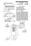
ABSTRACT
I
A portable electronic basketball game having a housing
[52] US. or. ......................... .>.. 273/85 G; 273/313
[58] "Field of Search ....... .._. ..... .. 273/85 G, 88, 94, 237,
4
273/DIG'_ 28, 1 E, 1 Ge; 340/323 R; 364/410;
6
Bromley ............................ .. 273/313
.
4 [73]‘ Assrgnee:v Mattel, Inc., Hawthorne, Calif.
121]
2/1981
Davld A. Relchert, Carson, Calif.
235/92 G A
Cit d~ '
e erences
e
2
-
4/1975
5,093,223
6/1978 'Wilke et al.
4,162,792
7/1979
the offensive players may pass between one another in a
preferred embodiment. The preferred embodiment also
featured a twenty-four second clock, a three-second
- AU.S. PATENT, DOCUMENTS
3,874,669
containing control circuitry and mounting a display and
‘ input controls The display shows both offensive and
defensive Players and a ban- The defensive Players may
be controlled to undertake a plurality of defenses and
clock, foul shots, and three-point long distance ?eld
Ariano et a1. .................. .. 273/85 G ' '
273/94
273/85 G ‘
Chang et a1. .... ..
80$
‘
15 Claims, 28 Drawing ?gures
36
more
D:
Leo Myra-e
61
ransom“ 16
7951]
Manet?
cowra
5.?
Vs,
4201.
Va» A‘
SLAVE. (a
CON TE_
52
Van
LB
Lo
CLDCK
CONTR
CKY
SLAVI
1 ON
:LAva
court 55?
To
can:
(:0
at».
c Incum
64:
U.S. Patent
gal,
Jul. 27; 1982
Sheet 1 of 13
4,341,383
U.S. Patent
F121.
Jul. 27, 1982
Sheet 2 0f 13
O
0
oi-hrbm
()PLDUJQ
?fe. 2 (d)
#16. 2 (e)
gw-noavb
Qr-BDWi
QH-nmJP
E61. 2(c)
#127. 2 (b)
(Q)
OI-LNWP
4,341,383 '
0
19.3456
F221. 20;)
P12. 201)
F370. 2(5)
PAT TEEN *1
PAT TE. 2H 1* O
ownua?
OMNl-b
(DH-7045
U.S. Patent
Jul. 27, 1982
Sheet 3 of 13
#22,. 2(k)
#12,. 2(4)
pm-TE QN *3
PATTERN *4
OF?
O
QLMNIP
01234.56
0123456,
FIE’. 2(m)
#141201)
0123456
PATTERN #5
—- ‘?
04x3)‘;
I
4,341,383
44432555
4
3443385543
24460055
2
1|looo22
i
OIYIHCDOOZZ
o
0123456
0123456
US. Patent
Jul. 27, 1982
Sh‘eet4 of 13
4,341,383
US. Patent
Jul. 27, 1982
Sheet 5 of 13
4,341,383
RECEIVE GAME STATUS
HZOM SLAVE OONWOUEE
PLAY SOUNDS
MQVE. ONE
oacausem
‘to ME
MOVE
‘220 EWEB
RECEIVER
.
_
PEA
COMPUTE NEXT Mo/E.
PER PRESENT PATTERN
COMPUTE NEiT
MOVE To BE.
CLOSER T0 BALL
PATTERN
CQMPLETED
MOVE. KEcENF-E
COMPUTE.
NEW PATTERN
E
U.S. Patent
4,341,383
Sheet 6 of 13
Jul. 27, 1982
TuME
To MOVE.
DEFENSE
SELECT RANDOM
NUMBER. 0 ~ 3
Gum
mnousz‘s
"°$“'\°"
DI-BnwAnoN *
BETWEEN BALL
?
% RECEIVER
‘(BLOW
NO
SEJ£cT RANDOM
"=8
&
NUMBER 0-?
DEsTmA'noN:
Woom MOVE.
\
DESTmA‘noN
V
1-. BASKET
\
DESTNA'HON -=.
BETWEEN BALL ‘
& BASKET
‘
L
‘
1
TRIAL wove.
WITH \N
PROPER
B OUNDAWES
V
FtaS
MAKE MovE.
US. Patent
Jul. 27, 1982
Shleet 8 of 13
4,341,383
BLANK DlSPLA‘u’
TURN on,
wAn', TusaN~
oFF BALL
HANDLER
HAS
BALL
TURN 0N,wA|T,
TURN-OFF
HANDLER.
TURN ON , WMT,
TURN-OFF
RECEIVE. R.
2M 0M. wAn;
TURN ON‘ WAIT,
TUQN“ OFF
DEF EN DER.
TURN ON,WA\T.
TURN-OFF
RIGHT men‘
US. Patent
Jul. 27, 1982
' Sheet 9 of 13
4,341,383
PASS KB’
suoor Km
PRESSED
PRESSED
sTOQE $HOT
COMPUTEBALL 3
‘N PROGRESS
VECTOR
STORE. PASS
IN PROGRESS
Tlmakm
Move-1 BALL.
MovE. BALL
k
DEFENDEK '
(:0 IN c \DENT
ADJACENT
HANDLER
\MTH DEFENDER
Y5
QO\NC\DF_NT
up
BALL
wnu DEFENDER.
CAUGHT BY
“0
RECENER
?
‘(B
BALL
Ya
SHOT
NO
AT BA$KET
?
V
ow
0F BOUNDS
'
_
?
no
was
NO
9
' Es
BOUNQE‘ BALL
"
OFF DEFENDER
EXCHANGE‘
‘
POSS\BLE
HANDLER &
,
TURNWER
RECENEE.
\
TURNOVER
YES
BASKET‘)
TURNOVEQ
NO
Pm. 9_
‘
‘
EX‘T
U.S. Patent
Sheet 10 of 13
Jul. 27, 1982
4,341,383
QUARTER
CLOCK
!
\NlT\AL.\lE
THREE. SECOND
SET NEW
Q LOCK
QUMZTEE
\N\T\ AL lZE.
2.4 SECOND
CLOCK
QUARTER
CLOCK =0
DECREMENT
DECREMENT
QUARTE 2
Z4 SECQN D
CLOCK
QLOCK
k
HANDLER.
IN KEY
\N\T\ ALIZE
THREE SECOND
cLocK
TURN OVER
DECEEMENT
THREE SECOND
CLOCK
SECOND CLOCK
P: O
F\ (41.40
US. Patent
Jul. 27, 1982
4,341,383
Sheet 11 of 13
START T IMER
oecaaMauT
Y Posmovk
OUT OF
800 N08
\NCREMENT
Y POSTION
' DECREMENT
X Posrnovl
I NCREMENT
DOES HANDLE '
ABORT NVVE
MINE HANDLER
MOVE HANDKEE
AND BALL.
V
F16. H
US. Patent
Jul. 27, 1982
Sheet 12 of 13
4,341,383
PASS OR
SHOO 1' KEY
DEPRESSED
‘2
START T\ MEE
"Ass
STORE PASS
Snoor
STORE SHOOT
\N\T\AL\ZE_
THQEE- SECOND
CLOCK
COMPUTE
FOUL.
PROBABwn-Y
“°
OF FOUL
FQ‘aUL
N0
P642
m
PROQQESS
Y
5°
EX\T
12
YES
EXEcUTE FOUL
\
FOUL souuo
U.S. Patent
FORMATION
‘
Jul. 27, 1982
DEGEEMENT
FOOLS
FOUL
FORMA‘HON
1
BALL
INTO
mamas
PLAY
Fug. i3
Sheet 13 0f 13
4,341,383
4,341,383
1
ELECTRONIC BASKETBALL GAME
BACKGROUND OF THE INVENTION
This invention relates to games and,‘ more particu
larly, to electronic games for simulating the play of
athletic games.
'
2
automatically by the data processing circuitry. The
i
'
People appear to have been involved in the playing of
games since the beginning of recorded history. The
almost universal interest in games seems to be due to the
excitement engendered by competition and chance.
Competitive games are probably more exciting, other
factors being equal; but, they normally require that a
number of persons be involved in each such game.
Many competitive games require a large, number of
players, large fields,‘ and a substantial amount of equip
ment.
handler may also shoot at the basket under control of
the operator. The defensive players reach automatically
under control of the data processing circuitry as would
human defenders under like circumstances to provide
zone, man-to-man, and pressing defenses selectable by
the operator. The preferred embodiment of the game
features a twenty-four second clock, a three-second
clock, foul shots, and three-point ?eld goals.
Other objects, features, and advantages of the inven
tion will become apparent by reference to the speci?ca
tion taken in conjunction with the drawings in which
like elements are referred to by like reference designa
tions throughout the several views.
BRIEF DESCRIPTION OF THE DRAWINGS
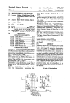
FIG. 1 is a perspective view of the exterior housing of
Recently, various improvements in electronic cir
an electronic basketball game constructed in .accor
cuitryhave allowed the reduction in size and cost of
data processing circuitry and have led to electronic
circuits which simulate the play of various ones of the
players in certain well known games. In these electronic
dance with the invention;
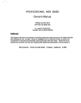
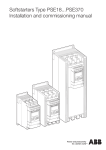
FIG. 2(a)-2_(p) illustrates different arrangements of a
display of the game illustrated in FIG. 1;
FIG. 3 is a schematic diagram of circuitry utilized in
games, a person moves an electronic player against
a preferred embodiment of the invention; and
>
electronic competitors thereby eliminating the necessity
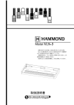
FIGS. 4-13 are ?ow charts showing the program and
for some or all of the other human players. Many of
operation of a preferred embodiment of the invention.
these electronic games are quite expensive. Often, the
game must be connected to a television set to provide a
DESCRIPTION OF THE PREFERRED
display upon which the game may be presented and,
consequently, cannot be moved from place to place.
EMBODIMENT
basketball, or baseball. These portable games have their
own built-in displays and are much less expensive, in
general, than those which must be connected to a televi
upper housing 12 and a lower housing 14 each of which
may be constructed of a moldable plastic material. The
housings 12 and 14 may be joined together in a conven
sion set. Their small size allows them to be carried about
tional manner to form a hollow interior for containing
Referring now to the drawings, and more particu
Recently, a number of portable electronic games 30 larly, to FIG. 1, there is shown a perspective view of an
have been devised by which one or two persons may
electronic basketball game 10 constructed in accor
play a particular simulated sports game such as football,
dance with this invention. The game 10 includes an
and used almost anywhere. However, these portable
electronic games have relatively small displays, contain
a limited amount of circuitry, and are usually powered
by battery. Consequently, the portable electronic games
heretofore devised have been relatively unsophisticated
as contrasted to those which are associated with televi
sion sets.
1
electronic components. The upper housing 12 mounts a
control panel 16 which includes a display 18, a speaker
19, and keys 20 through 29. The key 20 is designated
‘“Off- 1 Pro 2;” the key 21, “Press;” the key 22, “Zone;”
the key 23 “Man,” the key 24, “Pass;” the key 25,
“Shoot;” the key 26, “Up;” the key 27, “Left;”- the key
28, “Down;” and the key 29, “Right.” On the bottom of
It is, consequently, an object of this invention to pro
lower housing 14, but not shown in FIG. 1, is a door for
vide a new and improved portable electronic basketball 45 providing access for insertion of conventional batteries,
game.
such as a nine volt transistor battery, to operate the
It is another object of this invention to provide a new
circuitry contained within the housing halves 12 and 14
and improved electronic game capable of simulating the
of the game 10.
play of a game of basketball at a sophisticated level.
In the play of the game there are shown on the dis
It is another object of this invention to provide an
play 18 two offensive players (designated handler H and
electronic basketball game operable at different levels
of sophistication.
SUMMARY OF THE INVENTION
The foregoing and other objects of the invention are
accomplished by a portable electronicbasketball game
which has an exterior housing mounting a display upon
which indications representing the various players, the
ball, and the results are presented. The housing also
mounts input keys for controlling the operation of the
game and contains electronic data processing circuitry
organized to provide the automatic play of a number of
different skill levels of basketball.
'
receiver R hereinafter), ?ve defensive players (desig
nated D0-D4 hereinafter) and a ball (designated B here
inafter). The movements of the players and the ball are
controlled by use of the keys 20 through 29.
The key 20 is used for switching the game 10 on at
either of the two skill levels, Pro 1 or Pro 2. In the Pro
1 skill level, play by the defense proceeds automatically
at a ?rst rate of speed. In the Pro 2 position of the key
60 20, play of the defensive men moves at a faster rate of
speed thereby substantially increasing the difficulty and
excitement of the game 10. Two faster speeds for the
defense are also possible as will be explained below.
Each defenseman is indicated on the display 18 by'a
Two offensive players, five defensive players, and. a
ball are represented on the display. The offensive player 65 dimly lit (in relation to the offense) light emitting diode
in the preferred embodiment.
having the ball (the handler) is controlled by the opera
The keys 21, 22, and 23 are used for causing the de
tor to move with the ball and to direct passes to the
fensemen to play in three defensive styles. When the
other offensive player (the receiver) which is moved
3
4,341,383
press key 21 is depressed four of the defensemen try to
surround the handler while the remaining defenseman
tries to position itself between the ball handler and the
pass receiver.
4
ceed toward the basket. A basket is scored by a ball B
reaching the position of the basket (row four, column
three) after traveling a horizontal, vertical, or diagonal
path from the handler H. If a defender D0-D4 is in the
path of the shot, the ball B bounces off of it and is taken
over by the ?rst player to reach the position of the ball
B. If a defenseman is in the path of a pass, it intercepts
the ball B except that a defenseman immediately adja
cent the handler H does not intercept the ball B. That is,
When zone key 22 is depressed, a defense is set up in
which each of the ?ve defensemen is restricted to its
own zone of play. These zones are shown in FIGS.
2(0)-2(d). In FIG. 2(a), for example, the defenseman
designated D0 may move in any of the squares indicated
by the cross hatching. The defensemen move in the
zone defense to follow one of three strategies depending
on how close the handler is to the basket. If the ball
handler is in the zone designated as green in FIG. 2(e),
the handler H may pass over a defender immediately
adjacent him and complete a pass to the receiver R. The
defenseman which intercepts the ball B becomes the
the defensemen move at random within their zones. If
new handler H, and a new out-of-bounds formation (See
to move in a manner in which two of the defensemen
basket positioned centrally above the matrix display.
D0 and D1 attempt to achieve positions between the
ball handler and the basket and the other three defense
opposite sides of the basket to show the score and time
the ball handler is within the zone designated as yellow 15 FIG. 2(0)) is then set up.
The display 18 in the preferred embodiment is a ?ve
in FIG. 2(e), the defenseman attempts to move in the
by
seven array of horizontally positioned light emitting
zones to be between the ball and the basket. If the ball
diodes (LEDs). For convenience, the rows of LEDs are
handler is in the red zone (referred to as the key) shown
labeled starting at the bottom in FIG. 2 from zero
in FIG. 2(e), the defensemen attempt to block a shot by
through four, and the columns starting at the left from
heading in the zones directly for the basket.
zero through six. An extra LED 32 is used to indicate a
The depression of the man key 23 causes the defense
Two seven segment LED digits 34 and 36 are used on
men stay in zone formations and tend to move to follow
remaining.
the ball. The zone formations for defensemen D2-D4
are shown in FIGS. 2(}‘) and 2(g). The man key 23 may
A game consists of four quarters each lasting twelve
simulated minutes. In the preferred embodiment, the
visiting team has the ball B at the start of the ?rst and
also be depressed when moving the key 20 to the Pro 1
third quarters while the home team has the ball at the
and Pro 2 positions to obtain third and fourth speeds for
movement of the defensemen D0-D4.
30 start of the second and fourth quarters. The visitors line
up to start play in the formation shown in FIG. 2(0)
The offense consists of the handler H and the receiver
with the handler H at the center and the receiver R at
R. The handler H is normally indicated by a brightly lit
the left in row zero. The home team lines up in the same
LED on the display 18, and the receiver R is normally
initial positions with the receiver R to the right, how
indicated by a bright but blinking LED on the display
18. If the ball B separates from the handler H, the LED 35 ever. If the score is tied at the end of any overtime
period, additional overtime periods are played until a
indicating the handler H also blinks. The handler H is
winner emerges.
maneuvered about the various positions on the court by
depression of the keys 26 through 29. Depression of any
The team remains on offense until the twenty-four
key 26 through 29 causes the handler H to move one
second clock has counted down to zero, the three
space in the direction indicated by the key. Depression
40 second clock has counted to zero with the handler H in
of two adjacent keys 2629 causes the handler H to
the key, a shot has been taken and missed and the de
fense has recovered the ball B, or a shot has been taken
and scored. At this point, the team previously on de
move one space on a diagonal between the direction
indicated by the two keys. The key 28 is also used to
cause the score of the teams and the time remaining in
play to be displayed when the ball is not in play.
The receiver R moves under control of the control
45
fense goes on offense (taking the original out-'of-bounds
formation). Before play starts, however, one of the
three defensive formation keys 21-23 must be depressed
circuitry of the game 10 in accordance with the position
to establish the defense. The new handler H is then
at which the handler H appears on the display 18.
controlled by the depression of keys 26 through 29
FIGS. 2(h) through 2(m) illustrates positions in which
until, in like manner, the ball B is turned over to the
the receiver R moves when the handler H is in any of 50 team on defense. The twenty-four second clock is reset
the positions shown in FIG. 2(n). For example, when
every time a shot is attempted. After each turnover, the
the ball handler H is in any of the positions designated
visitor’s score, the home score, and the time remaining
four in FIG. 2(n), the receiver R moves through the
are displayed. The ball may also be turned over if it is
positions shown in FIG. 2(1). When the handler H is in
shot or passed out of bounds or if a quarter ends.
any of the other positions zero through ?ve shownin 55 Each time a shot is taken the control circuitry of the
FIG. 2(n), the receiver R moves as is shown in the
others of FIGS. 2(h)-2(m).
Depression of the pass key 24 causes the control
game 10 determines on a random basis whether the
handler H has been fouled. The closer the handler H is
to the basket, the more likely it is that a foul has taken
circuitry of the game 10 to direct the ball B in the gen
place. When a foul is determined to have occurred, a
eral direction of the receiver R which then seeks the 60 foul sound is given and the ball continues on its way. If
ball B by trying to move into its path. If the receiver R
the shot is missed, the offense gets two free throws. If
moves into the path of the ball B, it receives the ball B
the shot is made and the shooter is fouled, the shooter is
and becomes the handler H controlled by the keys 26
awarded one free throw. In another embodiment, if the
through 29. In such case, the old handler H becomes the
shot is missed, the offense receives up to three chances
receiver R and begins to blink.
65 to make two successful throws if the opponent’s defense
Depression of the shoot key 25 causes the control - has committed more than four fouls during the present
circuitry of the game 10 to separate the indication of the
period of play. If a free throw is required, the teams
ball B from the handler H and causes the ball B to pro
arrange themselves in the free throw formation shown
5
4,341,383
in FIG. 2(p) with the receiver R lined up on the same
‘side of the key which it takes on an out-of-bounds play.
‘A free throw is taken by the operator pressing the
' shoot key 25 when the teams are in the free throw for
mation which is automatically set up by the control
6
Various controller circuits are offered by a number of
manufacturers and are well known to the prior art. A
preferred embodiment of the present invention uses two
COP 420L Microcontrollers manufactured by National
Semiconductor. The circuit is better described in the
circuitry. In the preferred embodiment, the shot goes in
COPs Chip User’s Manual published by National Semi
or not depending on a random probability generated by
‘the control circuitry of the game 10. If a last free throw
conductor.
As may be seen in FIG. 3, the closure of the various
misses, the missed shot rebounds off the basket, be
keys 21-29 provides input signals at terminals IN019,
comes live, and may be picked up by either team.
If a shot is taken and scored and the ball is shot from
the green zone shown in FIG. 2(2) and a basketis made,
IN19, IN210, and IN320 of the slave controller 56. A
closure of the keys 21-29 also provides connections to
7 three points are awarded tothe offensive‘ team for a
_ three point ?eld goal. The preferred embodiment uses a
i the display 18 which, as shown in FIG. 3, comprise a
number of LEDs ‘30 and 32 and the LED digits 34 and ~
36 connected in the arrangement above described. Input
signals to the display 18 from the controller 56 are fur
nished at terminals D0-D3 and Gil-G3. Communica
point ?eld goal. Any other basket is worth two points
tion with controller 58 is provided at terminals L0-L7.
except foul shots which are each worth a single point.
Reset pulses are provided at a‘reset terminal on control
‘ Referring now to FIG. 3 there is shown a block dia
ler 56 by reset circuitry including a diode 60 connected
gram of the circuit of the invention. The game 10 shown
in ‘FIG. 3 includes the input keys or switches 20-29. 20 in parallel with a resistor 62 and to a capacitor 64. The
reset circuitry is connected to the terminals VSS and
Each of the switches 21-29 is shown as a normally open
VDD in order to supply power for its operation. Tim
switch which upon depression of a button closes a cur
ing pulses are provided to the controller 56 at a terminal
rent path thereacross. The switch 20 is shown as a three
CKI by a clock control circuit 66.
position, two-pole, make-before-break, slide switch.
The master controller 58 provides output signals at a
Power is ‘furnished to the game 10 from a source of 25
terminal G1 for operating a piezoelectric speaker 70 and
DC power 50 which is connected to'the switch 20 in
at terminals L0-L7 for communication with controller
parallel with an AC jack 52 (which allows house cur
56. Timing pulses for the master controller 58 are pro
rent to be applied through a transformer not shown)
line on the display 18 to illustrate the range for a three
vided at a terminal CK] from the circuit 66. The con
across a capacitor 54 through a diode 55. The switch 20
connects to a ?rst controller 56 at terminals VDD and 30 troller 58 is also connected to the source 50 at its termi
nals VDD and VSS in a manner identical to the chip 56.
VSS. The switch 20 also allows the keys 21-23 ,(which
select the form of defense) to be connected into cir
cuitry leading to an input terminal 1N3 in the P2 position
of the switch 20 and to be disconnected in the other
positions of the switch 20.
‘
The controller 58 receives reset pulses from reset cir
cuitry including the diode 60 at its reset input terminal.
FIG. 4 describes the overall operation of a preferred
35 embodiment of master controller 58 described above.
As will be understood by those skilled in the art, the
controller 56 (and a controller 58 to be discussed herein
after) may be implemented in any of a number of differ
As may be seen in FIG. 4, the master controller 58
receives information regarding the game status from the
tion utilizes an integrated circuit microprocessor (a
program moves to a step in which the sounds are gener
miniature digital electronic computer). Such integrated
ated by controller 58 and played by means of the
speaker 19. The program then recirculates to the step in
which it awaits the receipt of the game status from the
slave controller 56 and moves to a decision step in
which it is determined whether and what sounds the
ent ways. However, as with many prior art electronic
‘ game circuits, the preferred embodiment of the inven 40 game 10 is to produce. If sounds are to be produced, the
circuit microprocessors are well known and include all
of the input, output, memory, logic, and control cir
cuitry of a special purpose digital computer in miniature
45 slave controller 56. The sound effects are generated on
form. In general, such circuits have. both random access
the'occurrence of certain situations in a game play and
memory (RAM memory) and read only memory (ROM
are listed below:
memory). The ROM memory has connections formed
One Whistle-Personal foul committed by the defense.
basic circuitry of the controller 56 to provide a com 50 Two Whistles-Blocked shot or pass, ball out of
bounds, or over twenty-four seconds without a shot
pletely wired circuit which includes the program for
by masking operations during the construction of the
controlling the operation of the microprocessor. Such
all of which caused a turnover.
Three Whistles-Handler has spent too much time in
the key causing a turnover.
ory circuit. The RAM memory of the circuit is utilized
for storage of the various transient bits of information 55 Two-note Fanfare-Free throw was good.
Four-note Fanfare-Field goal was good.
and program during the operation of the circuitry. ‘
an arrangement is often described as a dedicated mem
Although many electronic games known to the prior
art utilize circuitry on a single chip, the present inven
tion utilizes two essentially identical controllers 56 and
58 which are individually masked in such a way as to
Double Fanfare-Three point ?eld goal scored.
Buzzer-End of each of the ?rst three quarters.
Two Buzzers-End of overtime period.
Long Buzzer—End of the game.
provide a substantial increase in the memory capability
If no sounds are to be produced after the receipt of
the game status, the program moves to a decision step in
which it is determined whether it is time to move a
controller 56 is designated, for convenience, the slave
controller and the controller 58 is designated the master 65 defenseman. If it is time to move a defenseman, the
program moves to a sub-routine in which the particular
controller because the control of communication be
defenseman to be moved and the particular move that
tween the controllers 56 and 58 resides in the controller
of the game 10 over those of the prior art so that more
sophisticated operations may be accomplished. The
58.
r
that defenseman shall make are determined. The pro
4,341,383
7
gram then recirculates to receive the game status from
the slave controller 56. If it is not time to move the
defense, the program moves to a decision step in which
it determines whether it is time to move the receiver R.
If it is time to move the receiver R, the program moves
to a step in which the particular move the receiver R is
to make is computed and the receiver R is moved. The
program then recirculates to the step in which the game
8
If the defense selected is the zone defense initiated by
depressing the zone key 22, the program moves to a
decision step in which the position of the handler H is
determined. FIG. 2(e) illustrates three areas in which
the handler H may be positioned which will cause dif
ferent operations by the zone defense. These are the
‘ green, yellow, and red zones illustrated in FIG. 2(e).
status is received from the slave controller 56. If it is not
If the handler is positioned within the green zone
shown in FIG. 2(e), the program branches to a step in
time to move the offensive receiver R, the program
which a vrandom number between zero and three is
recirculates directlyto the step at which it receivesv the
game status from the slave controller 56.
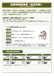
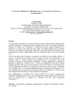
FIG. 5 illustrates the steps taken in the preferred
embodiment in the sub-routine which implements the
step of moving a defenseman in FIG. 4. As may be seen
in FIG. 5, the program moves from the step in which
selected and then to a decision step in which it is deter
mined whether the random number selected is zero. If
the random number is not zero (that is, in three out of
four cases), the program moves to select the destination
for the particular defender randomly chosen as the mid
point between the ball and the basket. The program
the determination as to whether it is time to move a
then moves to the step in which a trial move of the
defenseman is accomplished to a step in which one of
the defenders is picked at random. Since there are ?ve
particular defender is attempted and to the decision step
defenders used in playing the game 10, the probability
of any particular defender being picked is one in ?ve.
20 place or not. Presuming that no collision will take place,
The program then moves to a decision step from
where it is determined whether a collision will take
the program moves to determine whether the particular
move selected is within the proper boundaries.
.
which a path is selected depending on whether the keys
21, 22, or 23 have been pressed. If key 21 has been
As may be seen from FIGS. 2(a)—2(d), each defender
D0-D4 may move only in particular spaces in a zone
depressed, the defensman should move in a pressing 25 defense. Thus, if the particular move selected is outside
defense; and the program moves to a decision step in
of the spaces to which that defender is limited in the
which it is determined whether the particular defender
selected at random to make the move is defender D0.
zone defense, the program moves to abort the move
selected and to exit the sub-routine. If the new move is
As will be recalled, in the pressing defense four defend
within the proper boundaries, the program then makes
' ers surround the handler while a single defender at
the move and exits the sub-routine.
If the random number selected in setting up the zone
defense when the handler H is in the green zone is zero,
the program moves to a step at which the destination
chosen for the selected defender is a random move one
tempts to position itself between the handler H and the
receiver R.
In a preferred embodiment, the defender D0 is the
defender selected to position itself between the handler
H and the receiver R. Consequently, if the defender
picked at random is the defender D0, the program
space from the present position of the particular de
fender. The program then moves to attempt a trial
moves to a step in which its destination is selected as the
move of the defender and through the remainder of the
sub-routine. Thus the defender in moving in a zone
program then moves to a step in which a trial move of
defense where the handler H is in the green zone will
the defender D0 closer to the chosen destination is 40 usually move to a mid point between the ball and the
made. After the trial move, the program moves to a
basket, but in approximately one out of four cases will
decision step in which it is determined whether a colli
move randomly one space from its present position.
sion would take place were the defender D0 to move to
When the zone defense is being played and the han
the trial position. If such a collision would occur, the
dler H is in the yellow zone shown in FIG. 2(e), the
move is cancelled; and no move of the defense takes 45 program moves to select a random number between
mid point between the ball B and the receiver R. The
place.
zero and seven. The program then moves to determine
If no collision would occur, the program moves to a
whether the number selected was zero. If the number
decision step in which it is determined whether the
selected is zero (in one out of eight cases), the program
move is within the proper boundaries. With a pressing
moves to set the destination for that defender as the
defense, the move will be within the proper boundaries '
in all cases, for there are no speci?c zones set up in
basket and to move through the remainder of the sub
routine. If the random number selected is not zero (in
seven out of eight cases), the program moves to set the
which a defender is constrained to move in the pressing
defense. Consequently, the program will move to a step
in which the move is executed and, thereafter, will exit
the sub-routine from moving the defense.
'
In executing the pressing defense, if it is determined
that the particular defender randomly selected is not
defender D0, then the program moves to a step where a
destination of the particular defender selected for the
move on this circulation of the program as the mid point
55 between the ball B and the basket.
The program then moves to attempt a trial move, to
determine whether a collision will take place, whether
the move is within the proper boundaries for a particu
destination for the defender mid way between the ball B
lar man in a zone defense, to make the move, and to
and the basket is selected. The program then attempts a 60 ?nally exit the sub-routine. Thus, where the handler H
trial move of the defender and determines whether a
is positioned in the yellow zone of play shown in FIG.
collision will occur. If a collision will occur with any of
2(e), the selected defenseman, in seven out ‘of eight
the defenders, the move is not taken on the particular
cases, moves to a mid point between the ball B and the
circulation of the program. If no collision will occur,
basket and in the other case moves for the basket to
the program moves to the decision step in which it is 65 block a shot. '
‘
determined whether the new move is within the proper .
If the handler H is positioned in the red zone shown
boundaries, to make the move, and to exit the sub-rou
in FIG. 2(e) and the defense is a zone defense, the pro
tine.
‘
gram moves to a step to set the destination for the se
4,341,383
10 '
lected defender as the basket thereby attempting to
{create a ring of players impeding the movement of the
ball B to the basket. As with the other defense setups,
the program then moves to attempt a trial move of the
defender to determine whether a collision will occur, to
determine whether the new move is within the proper
boundaries, and to make the proper move.
FIG. 6 illustrates the steps of a sub-routine of the
preferred embodiment of the program for moving the
receiver R. This sub-routine may be used to implement
the Move Receiver step shown in FIG. 4. After‘deter
mining that it is time to move the receiver R (as shown
in FIG. 4), the program moves to a decision step at
which it is determined whether there is presently in
?ashing LED, the defensemen by dimly lit LEDs, and
the ball B by a brightly lit LED when separated from
the handler H.
The program moves from the step in which the posi
tions of the players on the display 18 are illuminated to
a step in which the input switches 20-29 are scanned to
determine which, if any, have been actuated. The pro
gram then moves through a series of decision steps to
determine whether any particular actions are necessary
because of switch closures. The program ?rst deter
mines whether the handler H is to be moved and then
completes the move. If the handler is not to move, the
program determines whether a shot or a pass has been
taken and executes the action. If a shot or pass has not
progress a pass from the handler H to the receiver R. If 15 been taken, the program determine whether a defense
has been keyed in and executes the defense. If a defense
has not been selected, the program determines whether
which the controller 58 computes the next position of
a speed change has occurred (the key 20 may be moved
_ receiver R according to the present pattern of the play
from position 1 to position 2 at any turnover) and‘imple
ers on display 18.
It will be recalled that when the handler H is in posi 20 ments the new speed.
From. completing any of these steps or if no action is
tions numbered zero through ?ve in FIG. 2(a), the
‘necessary, the program moves to a decision step in
receiver R moves as shown in the patterns associated
which it is determined whether to move the ball B or
with the numbers zero through ?ve in FIGS. 2(h)-2(m).
not. If the ball should not be moved, the program ad
For example, if the handler H is in one ‘of the positions
numbered ?ve in FIG. 2(n), the receiver R moves as 25 vances to a step to accomplish various timing and clock
no pass is in progress, the program moves to a step in
shown by the arrows in FIG. 2(m). Once the receiver R
has begun such a pattern, it continues one complete
cycle; then the controller 58 looks at the new position of
functions including determining whether the twenty
four second clock has expired, the handler H has been in
the key for more than three seconds, or a quarter has
the handler H and starts the receiver R running a new
elapsed. If the twenty-four second clock has expired or
pattern. Thus, the next position for the receiver R is
normally the next position in the pattern presently being
30 a three-second violation has occurred, the program
run.
moves to turn over the ball to the opponent. If the end
of a quarter has occurred, the program moves to a deci
The program then moves to a decision step at which
it is determined whether a move to the selected position
sion step to determine whether the end of the game has
occurred. If neither the end of the quarter, the expira
' for the receiver R will result in a collision with another
tion of the twenty-four second clock, nor a three
second violation has occurred, the program moves to a
player. If a collision will result, the program moves to
exit the sub-routine. If a collision will result, the re
step at which the game status is sent to the master con
ceiver R is moved and the program moves to a decision
troller 58.
If the end of the‘ game has occurred, the program
step to determine whether the present movement pat
tern has been completed. If it has not, the program exits
the sub-routine. If the pattern has been completed, then
the program moves to compute a new pattern for move
ment of the receiver R as explained above.
If a pass is in progress between the handler H and the
receiver R when it is time to move the receiver R, the
program moves to compute the next move for the re
moves to a decision step at which it is determined
whether the score is tied so that an overtime is neces
sary. If the score is not tied, the program moves to a
step to indicate that the game is over, to a step to deacti
vate the switches 21-29, and on to the step in which the
game status is sent to the master controller 58. If the
score is tied at the end of the game, the program moves
to a step to provide a ?ve minute overtime, then to the
step to send the status of the game to the master control
ceiver R to place the receiver R closer to the ball B so
that the ball B may be received. The program then
ler 58.
moves to the step to determine whether in the new
If the ball B needs to be moved at the Move Ball step,
position a collision will result, to make the move if no 50
the program moves to a step in which the ball is moved
collision would result, to determine whether the pattern
and then to a decision step to determine whether a score
of movement for the receiver R has been completed, to
has occurred. If no score has occurred, the program
compute a new pattern if it has been completed, and to
moves to the step at which the timing and clock func
exit the program (all as explained above).
tions are taken care of and then to the remainder of the
FIG. 7 illustrates the steps of the program in the
program as explained above. If a score has been made,
operation of the slave controller 56 in the preferred
the program moves to a ?rst step to register the points
embodiment of the invention. FIG. 7 begins with a step
in which the various positions representing players on
the display 18 are illuminated. The particular positions
of the display 18 are more fully illustrated in FIG. 3 in
which are shown a series of LEDs 30 arranged in col
and then to a decision step to determine whether a
turnover‘ of the ball B has occurred. If no turnover of
the ball B has occurred, the program moves to the step
umns from zero at the left through six and rows from
for implementing the timing and clock functions and
continues through the program as explained above.
zero at the bottom through four. Any particular LED
If a turnover of the ball takes place after a score as on
a ?eld goal without a foul or on a last foul shot, the ball
30 is illuminated by energization of a conductor in a row
and a conductor in a column leading to the particular 65 moves to set up a new initial formation in which the ball
is given to the opponent. As explained above, FIG. 2(0)
LED 30 at the intersection of the two conductors. As
illustrates this initial formation for the visiting team on
explained above, the handler H is usually shown by a
offense. The program, then moves to the step in which
brightly lit LED, the receiver R by a brightly lit but
11
4,341,383
the game status is relayed to the master controller 58
and from that step recycles to the step for illuminating
the various display positions (as explained above).
FIG. 8 illustrates the sub-routine illustrated in the
preferred embodiment for lighting up the display, the
l2
mined whether the shoot key 25 has been depressed or
not. If it has not been depressed, theprogram moves to
determine whether the pass key 24 has been depressed
or not. If neither key 24 nor 25 has been depressed, the
program moves to exit the sub-routine.
‘ If the shoot key 25 or the pass key 24 has been de
pressed, the program moves to store the fact either that
?rst step shown in FIG. 7. The ?rst step in the program
of FIG. 8 is to blank out all of the LEDs of the display
18. The program than proceeds to a step at which the
a shot is in progress or that a pass is in progress and the
LED 30 which is at the present position of the ball B is
moves to a step at‘which the vector of the ball B is
?rst switched on for a short period then off. The period 0 computed. The ball can travel in any of eight directions
of time during which any LED 30 representing the ball
up, down, to the right, to the left, and on any forty-?ve
B or a player remains on is, with the repetition of the
degree diagonal between these directions. When the
illumination cycle, suf?cient that the image of the ball B
vector has been computed, the program moves to the
appears to persist on the display 18.
decision step to determine whether it is time to move
The program next moves to a decision step at which
it is determined whether the handler H has possession of
the ball B. If the handler H does not have possession of
the ball at this step, the handler H must be individually
the ball B or not.
'
If it is not time to move the ball B, the program exits
the sub-routine. If it is time to move the ball B, the
program moves to a step at which the ball B is advanced
lit; and the program moves to an additional decision
one space according to the vector determined. The
step where it is determined whether the handler H il 20 program then moves to a decision step at which it is
lumination on display 18 is on or off. The handler H
determined whether the movement is part of a pass or
blinks when the ball B is not held; consequently, the
not. In a pass, the ball may be intercepted by a defender
LED 30 representing the handler H is not illuminated
in its path while a shot bounces off a defender in path.
on each cycle of the program. If the LED 30 which
Thus,
if the movement of the ball B is part of a pass, the
represents the handler H should be on, then the pro 25
program moves to a step to determine whether the ball
gram moves to turn on the LED 30 which represents
B is coincident with a defender. If not, the program
the handler H, to wait a particular interval with that
LED 30 on, and ?nally to turn off the LED 30 repre
senting the ball handler H.
The program then moves to a step to determine
whether the pass receiver should be on or off. If the ball
handler H should not have been on at last mentioned
decision step or if the handler H has possession of the
ball B, the program moves immediately to determine
whether the receiver R should be illuminated or not.
The receiver R blinks at all times so, like the handler H,
is not illuminated on each cycle.
If the receiver should be illuminated at the particular
cycle, the program moves to turn on the LED 30 which
moves to determine whether the ball B is caught by the
receiver R. If the ball B is caught by the receiver R, the
receiver R becomes the handler H and the keys 26-29
now control the new handler H (the previous receiver
R). The program then moves to exit the sub-routine. If
the ball B is not caught by the receiver R, the program
moves to a decision step to determine whether the ball
. B went out of bounds. If the ball B did not go out of
bounds, the program moves to implement a turnover
and exits the sub-routine.
If on a pass the ball B is coincident with a defender,
the program moves to determine whether the defender
represents the receiver R, to wait a designated interval, 40 is adjacent the handler H because the handler H may
pass the ball B over a defender immediately adjacent
and then to turn off the LED 30 representing the re
without an interception. Consequently, if the defender
ceiver R. The program then moves to a series of step at
is not adjacent the handler H, the program moves to set
which each of the defensemen D?-D4 is turned on one
up a turnover and then exits the sub-routine. If the de
at a time. In accomplishing this step, the program
moves to turn on an LED 30 representing’ the present 45 fender is adjacent to the handler H, then the program
exits the sub-routine.
position of a ?rst defenseman, to wait an interval, and
If a pass is not taking place (a shot is occurring or the
?nally to turn off the particular LED 30 representing
ball is free), the program moves to determine whether
the particular defenseman. The program then moves to
the ball B is coincident with a defender. If the ball B is
a decision step to determine whether all defensemen
have been illuminated on the display 18. If they have '
not, the program recirculates to turn on the remaining
defensemen and, ultimately, exits the decision step
when all of the defensemen have been illuminated.
The program next moves to illuminate the digit 34 of
display 18, to wait an appropriate interval, and ?nally _to
turn off the LEDs of digit 34. The program then moves
to turn on the LEDs of digit 36, to wait an appropriate
interval, and ?nally to turn off the LEDs of digit 36.
Finally the program exits the light display step of FIG.
7
coincident with a defender, the program moves to de
termine whether the ball B is being shot and, if it is, to
bounce the ball B off the defender as a loose ball. The
program then exits the sub-routine. If the ball B is not
being shot, the program moves to accomplish a tum
over and exits the sub-routine.
If the ball B is not coincident with a defender, the
program moves to determine whether the ball B is at the
basket. If it is, then the program moves to a decision
step to determine if a shot was taken, then to score a
basket and establish a turnover if a shot was taken, and
FIG. 9 is a sub-routine for the Move Ball step of FIG.
exits the sub-routine. The step at which a basket is
7 for the preferred embodiment of the invention. The
scored includes determining whether the shot traveled
?rst step illustrated in FIG. 9 is a decision step in which
from a position in the green zone shown in FIG. 2(e)
it is determined whether the ball B is free of handler H
and, consequently should be counted as two or three
or not. If the ball B is free, the program moves directly 65 points. If no shot was taken, the program exits the sub
to a decision step at which it is determined whether it is . routine. If the ball is not at the basket, the program
time to move the ball B or not. If the ball B is not free,
moves to determine whether the ball is out of bounds
the program moves to a decision step where it is deter
and proceeds as explained above.