1
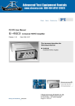
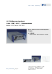
PZ176E User Manual
E-464 PICA™ HVPZT - Piezo Amplifier
Release: 1.0.1 Date: 10.07.2007
This document describes the following
product:
■
E-464.00
PICA™ HVPZT - Piezo Amplifier, 3 Channels
© Physik Instrumente (PI) GmbH & Co. KG
Auf der Römerstr. 1 ⋅ 76228 Karlsruhe, Germany
Tel. +49 721 4846-0 ⋅ Fax: +49 721 4846-299
[email protected] ⋅ www.pi.ws
Physik Instrumente (PI) GmbH & Co. KG is the owner of the following company names and trademarks:
PI®, PICA™
Copyright 1999–2007 by Physik Instrumente (PI) GmbH & Co. KG, Karlsruhe, Germany.
The text, photographs and drawings in this manual enjoy copyright protection. With regard thereto, Physik
Instrumente (PI) GmbH & Co. KG reserves all rights. Use of said text, photographs and drawings is
permitted only in part and only upon citation of the source.
First printing 10.07.2007
Document Number PZ176E BSc, Release 1.0.1
E-464_User_PZ176E.doc
Subject to change without notice. This manual is superseded by any new release. The newest release is
available for download atwww.pi.ws (http://www.pi.ws).
Declaration of
Conformity
according to ISO / IEC Guide 22 and EN 45014
Manufacturer:
Manufacturer´s
Address:
Physik Instrumente (PI)
GmbH & Co. KG
Auf der Römerstrasse 1
D-76228 Karlsruhe,
Germany
The manufacturer hereby declares that the product
Power Amplifier for HVPZT
Product Name:
Model Numbers:
E-464
Product Options:
all
complies with the following European directives:
73/23/EEC, Low voltage directive
89/336/EEC, EMC-Directive
The applied standards certifying the conformity are listed below.
Electromagnetic Emission:
EN 61000-6-3, EN 55011
Electromagnetic Immunity:
EN 61000-6-1
Safety (Low Voltage Directive):
EN 61010-1
February 19, 2007
Karlsruhe, Germany
Dr. Karl
Spanner
President
About this Document
Users of this Manual
This manual is designed to help the reader to install and operate the E-464 PICA™ HVPZT - Piezo
Amplifier. It assumes that the reader has a fundamental understanding of motion control concepts and
applicable safety procedures.
The manual describes the physical specifications and dimensions of the E-464 PICA™ HVPZT - Piezo
Amplifier as well as the installation procedures which are required to put the system into operation.
Conventions
The notes and symbols used in this manual have the following meanings:
WARNING
Calls attention to a procedure, practice or condition which, if not
correctly performed or adhered to, could result in injury or death.
DANGER
Indicates the presence of high voltage (> 50 V). Calls attention to a
procedure, practice or condition which, if not correctly performed or
adhered to, could result in injury or death.
CAUTION
Calls attention to a procedure, practice, or condition which, if not
correctly performed or adhered to, could result in damage to equipment.
NOTE
Provides additional information or application hints.
The motion controller and the software tools which might be mentioned in this documentation are
described in their own manuals. All documents are available as PDF files via download from the PI
Website (www.pi.ws (http://www.pi.ws)). For updated releases contact your Physik Instrumente sales
engineer or write [email protected] (mailto:[email protected]).
!
Contents
1
Introduction
1.1
1.2
1.3
1.4
1.5
2
Overview ............................................................................................. 2
Prescribed Use.................................................................................... 2
Safety Precautions .............................................................................. 3
Computer Control................................................................................ 4
Unpacking ........................................................................................... 5
Operation
2.1
2.2
2.3
3
4
Analog Operation ................................................................................ 8
First Operation .................................................................................... 9
13
Specifications .................................................................................... 13
Frequency Response Diagram ......................................................... 14
Connectors........................................................................................ 15
5.3.1
6
12
Customer Service.............................................................................. 12
Technical Data
5.1
5.2
5.3
10
AC Power and Line Power Fuses ..................................................... 10
Cleaning ............................................................................................ 11
Troubleshooting
4.1
5
Bipolar Piezo Actuators ........................................................................ 8
Unipolar Piezo Actuators ...................................................................... 8
Wiring Example..................................................................................... 8
Maintenance
3.1
3.2
6
Front and Rear Panel Elements.......................................................... 6
Line Voltage Connection ..................................................................... 6
Piezo Actuator Connection.................................................................. 7
2.3.1
2.3.2
2.3.3
2.4
2.5
2
Index
2-Pin High-Voltage Connector............................................................ 15
17
Introduction
1
Introduction
1.1
Overview
Figure 1: E-464 bench top piezo amplifier for three channels
The E-464 is a bench-top piezo driver/amplifier for PICA™ high-voltage
PZTs. Its three low-noise, 4-quadrant amplifiers provide a gain of 100 and
can output and sink a peak current of 25 mA and an average current of > 3
mA each. If only 1 channel is operated, an average output power of 12 W can
be achieved.
Three 3½-digit LED displays show the output voltage of each individual
channel.
Analog Control
E-464 amplifiers are designed to provide precise control of open-loop piezo
positioning systems. The amplifier output voltage is determined by the
analog signal at the Control Input combined with the DC-offset potentiometer
setting.
1.2
Prescribed Use
Based on their design and realization, E-464 PICA™ HVPZT - Piezo
Amplifiers are intended to drive capacitive loads, in the present case,
piezoceramic actuators. E-464s must not be used for applications other than
stated in this manual, especially not for driving ohmic (resistive) or inductive
loads.
Observe the safety precautions given in this User Manual.
The E-464 meets the specifications as defined by DIN EN 61010 for safe
operation under normal ambient conditions. See the specifications table for
details (see "Specifications" p. 13).
www.pi.ws
E-464 PZ176E Release 1.0.1
Page 2
Introduction
1.3
Safety Precautions
Carefully read also the user manuals and/or technical notes of all other
components involved, such as controllers or software.
Failure to heed warnings in this manual can result in bodily injury or material
damage or loss of warranty.
DANGER—HIGH VOLTAGE
E-464 Power Amplifiers output VERY HIGH VOLTAGES and HIGH
CURRENTS which can cause death or injury!
Take special care if connecting products from other manufactures.
Follow general accident prevention rules!
Working with these devices requires adequately trained and educated
operating personnel.
During operation, do NOT touch any part which might be connected to
the HV output!
WARNING
PZTs Sensitive to Overvoltage or Reverse Polarity
Exposing some PZTs to voltages too far outside their operating range
will destroy the active element in the actuator. Make sure that both the
polarity and the voltage as seen by the PZT are within the allowable
range.
Be especially vigilant regarding polarity when using older actuators,
adapter cables and controllers set up for non-standard voltage ranges.
!
www.pi.ws
CAUTION
Read this before operating the equipment covered in this manual.
Always keep the User Manual safe and close to the described device. In
case of loss or damage to the instructions, please order a new copy from
your PI distributor or download one from www.pi.ws (http://www.pi.ws).
Also keep and add all further information (e.g. extended instructions or
Technical Notes) to the User Manual.
E-464 PZ176E Release 1.0.1
Page 3
Introduction
CAUTION—AIR CIRCULATION
Do not cover the ventilation slots on the top side of the E-464. The
device needs to be installed horizontally with 3 cm air circulation area.
Vertical mounting prevents internal convection. Insufficient air flow will
cause overheating and premature failure.
1.4
Computer Control
Optionally digital control via a D/A converter is possible. For several D/A
boards from National Instruments PI offers a corresponding LabVIEW¢
driver set which is compatible with the PI General Command Set (GCS), the
command set used by all PI controllers. A further option includes the
patented Hyperbit¢ technology providing enhanced system resolution.
E-500.ACD
CD with Driver Set for Analog Controllers, available free
of charge upon request
Computer control can be implemented using a
DAC-board in a PC to generate the analog input signal. PI
offers a LabVIEW™ driver set which can be used with
certain D/A boards. This driver set is compatible with the
PI General Command Set (GCS) LabVIEW™ driver set
available for all newer controllers from PI.
The PI Analog Controller drivers support all D/A converter
boards from National Instruments that are compatible
with DAQmx8.3. LabVIEW™ compatibility is given from
version 7.1 upwards. Connection of a sensor monitor
signal from a sensor- or servo-module (e.g. E-509) is
required.
The driver set is also available for download from the PI
website.
E-500.HCD
www.pi.ws
Access to HyperBit™ Functionality for Enhanced System
Resolution
(Supports certain D/A boards.)
PI’s patented Hyperbit™ technology for providing position
resolution higher than that of the D/A board is in the
E-500.ACD driver set. Activating Hyperbit™ requires
purchase of the password, which can be obtained from PI
under Order No. E-500.HCD.
E-464 PZ176E Release 1.0.1
Page 4
!
Introduction
1.5
Unpacking
Unpack the E-464 PICA™ HVPZT - Piezo Amplifier with care. Compare the
contents against the items covered by the contract and against the packing
list.
The following components are included:
E-464.00
HVPZT Piezo Amplifier, 3 Channels, 1100 V,
Bench-Top
3763
line cord
PZ176E
User Manual for E-464.00 (this document)
E500T0011
Technical Note for GCS LabVIEW driver set
Inspect the contents for signs of damage. If parts are missing or you notice
signs of damage, contact PI immediately.
Save all packing materials in case the product need be shipped again.
www.pi.ws
E-464 PZ176E Release 1.0.1
Page 5
Operation
2
Operation
2.1
Front and Rear Panel Elements
Figure 2: E-464 front panel with operating elements
The E-464 amplifier has 3 amplifier channels. Every channel provides the
following operating elements:
DC Offset turning knob
10-turn potentiometer for DC Offset (see
"Analog Operation" p. 8)
"CONTROL INPUT" BNC
socket
Connection of control signal (see "Analog
Operation" p. 8)
"HV-PZT" LEMO socket
High-voltage output for PZT (see "Connectors"
p. 14)
3 ½-digits LED Display
Display for PZT high-voltage
The power connection (see "Line Voltage Connection" p. 6), input voltage
selection and line fuses (p. 10) are located on the rear panel.
2.2
Line Voltage Connection
Unless you request otherwise, upon delivery the E-464 will be set up for the
voltage predominant in your country, either
115 V ~ / 50-60 Hz
or
230 V ~ / 50-60 Hz
To adapt the E-464 to a different line voltage, the line power fuses must be
replaced. See AC Power and Line Power Fuses (p. 10) for instructions and
for the required fuse types.
Connect the included line cord from the E-464 rear panel to an appropriate
power outlet.
www.pi.ws
E-464 PZ176E Release 1.0.1
Page 6
Operation
2.3
Piezo Actuator Connection
DANGER—HIGH VOLTAGE
E-464 Power Amplifiers output VERY HIGH VOLTAGES and HIGH
CURRENTS which can cause death or injury!
Take special care if connecting products from other manufactures.
Follow general accident prevention rules!
Working with these devices requires adequately trained and educated
operating personnel.
During operation, do NOT touch any part which might be connected to
the HV output!
DANGER—IMPROPER WIRING CAN CAUSE
DEATH, INJURY, DAMAGE AND VOID
WARRANTY
Modification of HIGH VOLTAGE Connectors should only be carried out
by the manufacturer. Any unauthorized modification may jeopardize
operating personnel. Treat HIGH VOLTAGES and HIGH CURRENTS
with respect.
Connect the piezo actuator to the E-464 HV output.
If you are connecting other actuators or wiring your own connector, read the
discussion of actuator type carefully and any documentation that came with
the actuator.
WARNING
PZTs Sensitive to Overvoltage or Reverse Polarity
Exposing some PZTs to voltages too far outside their operating range
will destroy the active element in the actuator. Make sure that both the
polarity and the voltage as seen by the PZT are within the allowable
range.
Be especially vigilant regarding polarity when using older actuators,
adapter cables and controllers set up for non-standard voltage ranges.
www.pi.ws
E-464 PZ176E Release 1.0.1
Page 7
Operation
2.3.1
Bipolar Piezo Actuators
Here the output voltage swing is so chosen that the actuator sees both
negative and positive high voltages. The output always has one lead at 0 V,
and here the other is in a zero-crossing range, commonly·±500·V.
2.3.2
Unipolar Piezo Actuators
The notation of "positive" and "negative" polarity of piezo actuators does not
refer to their direction of motion. Unipolar piezos of any polarity will elongate
when a higher voltage is applied to their (+) than to their (-) terminal.
"Positive" and "negative" refers to the sign of the voltage on the core of the
cable.
All standard PI piezo actuators with 3-conductor LEMO connectors have
positive polarity.
2.3.3
Wiring Example
In the wiring example shown at right, a
"positive" piezo is connected so as to
have 0 to +1100 V applied. To achieve
this, the positive terminal (possibly
labeled "+1100 V") is connected to the
variable HV-Out and the negative
terminal to PGND.
2.4
Analog Operation
The output voltage is controlled by an analog signal (Control IN) applied to
the BNC input added the DC-offset voltage. The magnitude of the sum must
be in a range equal to 1/100th of the factory-set output voltage range (usually
to 1100 V).
Control In Signal
The external voltage applied to the "Control In" BNC socket can be anywhere
in the range of -10 to +10 V, but may not have an active swing more than 11
V wide.
www.pi.ws
E-464 PZ176E Release 1.0.1
Page 8
Operation
DC Offset potentiometer
Depending on the position of the potentiometer, a DC voltage between 0 and
10 V is made available. If you require a constant DC-offset (e.g. 0), make
sure the knob stays at the required position.
NOTE
Due to the constant gain of 100 the range of the Amplifier IN signal is set
to 1/100 of the output voltage range. If an optional output range is set
the Amplifier In signal has to be chosen accordingly.
The analog control signal range is always 1/100 of the output voltage
range.
2.5
First Operation
1
Connect the sensor cable to the corresponding socket
2
Turn the DC offset potentiometer full counterclockwise (CCW)
3
Make sure that voltage at "Control In" is set to 0 V
4
Connect the amplifier to line power. The connection is on the rear
panel, see "Line Voltage Connection" section (see "Line Voltage
Connection" p. 6)
5
Turn on the line power
6
Command the first motion of the piezo actuator by turning the offset
potentiometer full clockwise (CW) then back full CCW to run the
actuator over the complete nominal travel range
The PZT voltage can be seen on the display, make sure that the full
voltage swing is attained
7
If an external analog signal is used, connect the signal source to the
"Control In" BNC socket. If the signal range is not 1/100 of the output
voltage
NOTE
If only one or two amplifier channels are operated, the full output power
becomes available to the channels in use (see specifications table).
www.pi.ws
E-464 PZ176E Release 1.0.1
Page 9
Maintenance
3
Maintenance
WARNING—LINE VOLTAGE
E-464s need to be installed in such a way that they can quickly and
easily be separated from the line voltage. Before cleaning the E-464,
changing the AC fuses and removing or installing modules, switch the
device off and disconnect it from the line power.
3.1
AC Power and Line Power Fuses
Unless otherwise requested, the unit will be set up for the power predominant
in your country. New line-power fuses are required when changing the
supply voltage.
CAUTION
!
Both fuses are active and have to be checked if there is a fault.
Figure 4: Fuse carrier
Figure 3: Position of the line fuses and fuse
carrier, only one of two fuses
visible
To access the line power fuses, proceed as follows:
www.pi.ws
1
Switch off the E-464 and remove the line cord
2
Wait a minute to be sure that any residual voltage has dissipated
E-464 PZ176E Release 1.0.1
Page 10
Maintenance
3.2
3
Pry open the door that covers the fuse carrier and pry out the fuse
carrier (see figures above)
4
Be sure to replace both fuses with fuses of the type appropriate for
the new voltage:
220 VAC to 240 VAC IEC * 0,8 AT (slow blow)
100 VAC to 120 VAC IEC* 1,6 AT (slow blow)
5
Rotate the fuse carrier so that the valid voltage setting (115 V or
230 V) will show through the window when the door is closed
6
Reinstall the carrier and close the door
Cleaning
The outside surface of the case can be cleaned using mild detergents or
disinfectant solutions. Organic solvents must not be used.
*
www.pi.ws
IEC fuses are cited: other fuse standards may require higher nominal current rating
E-464 PZ176E Release 1.0.1
Page 11
Troubleshooting
4
Troubleshooting
Positioner does not move.
Cables not connected properly:
■ Check the connecting cables.
■
4.1
Note the required voltage range for the analog signal at "Control In".
The control input range is basically one one-hundredth of the output
voltage (see "Analog Operation" p. 8)
Customer Service
Still having problems? Call your PI representative or write to [email protected];
please have the following information about your system ready:
www.pi.ws
■
Product codes and serial numbers of all products in the system
■
Current firmware version of the controller (if present)
■
Software version of drivers and / or host software (if present)
■
Operating system on host PC (if present)
E-464 PZ176E Release 1.0.1
Page 12
Technical Data
5
Technical Data
5.1
Specifications
E-464.00
Function
Power amplifier for PICA™ high-voltage PZTs
Amplifier
Output voltage
0 to +1000 V
(optionally: -250 to +750; -500 to +500; +250 to -750;
0 to -1000)
Amplifier channels
3
Average output power per channel >3.5 W (up to 12 W if 1 channel is operated)
Peak output power per channel, < 25 W
5 ms
Average current per channel
>3.5 mA (up to 12 mA if 1 channel is operated)
Peak current per channel, < 5ms
25 mA
Amplifier bandwidth, small signal
1 kHz
Amplifier bandwidth, large signal
3.5 Hz(660 nF); 35 Hz (70 nF)
Ripple, noise
0 to 100 kHz
5 mVRMS
Current limitation
Short-circuit-proof
Voltage gain
+100 ±1
Control input voltage
0 to 10 V
Input impedance
100 kΩ
50 mVP-P (100 nF)
Interface and operation
PZT voltage output socket
LEMO EGG.0B.701.CJL1173
Control input socket
3 x BNC
DC Offset
3 x 10-turn pot, adds 0 to +10 V to Control IN
Display
3 x 3½-digit LED display for output voltages
Miscellaneous
www.pi.ws
Operating voltage
100 - 120 or 220 - 240 VAC, selectable (fuse change
required)
Operating temperature range
+5°C to +50°C (over 40°C, max. av. power derated
10%)
E-464 PZ176E Release 1.0.1
Page 13
Technical Data
5.2
Mass
4.3 kg
Dimensions
236 x 88 x 273 mm + handles
Frequency Response Diagram
Figure 5: E-464, operating limits with various PZT loads. Values shown are
capacitance in nF
www.pi.ws
E-464 PZ176E Release 1.0.1
Page 14
Technical Data
5.3
Connectors
5.3.1
2-Pin High-Voltage Connector
DANGER—IMPROPER WIRING CAN CAUSE
DEATH, INJURY, DAMAGE AND VOID
WARRANTY
Modification of HIGH VOLTAGE Connectors should only be carried out
by the manufacturer. Any unauthorized modification may jeopardize
operating personnel. Treat HIGH VOLTAGES and HIGH CURRENTS
with respect.
Typ: LEMO
EGG.0B.701.CJL.1173
Pin Assignments:
HV OUT: HV output, up to 1100 V
PGND: Power ground
Housing: cable shield, for
protective ground
www.pi.ws
E-464 PZ176E Release 1.0.1
Page 15
6
Index
O
Operation • 6
Overview • 2
2
P
2-Pin High-Voltage Connector • 14
Piezo Actuator Connection • 7
Prescribed Use • 2
A
AC Power and Line Power Fuses • 6, 10
Analog Operation • 6, 8, 12
Analog signal • 8, 12
B
Bipolar Piezo Actuators • 8
C
Cleaning • 11
Computer Control • 4
Connectors • 6, 14
Customer Service • 12
S
Safety Precautions • 3
Scope of delivery • 5
Specifications • 2, 13
T
Technical Data • 13
Troubleshooting • 12
U
Unipolar Piezo Actuators • 8
Unpacking • 5
D
W
DC Offset potentiometer • 8
Wiring Example • 8
F
First Operation • 9
Frequency Response Diagram • 14
Front and Rear Panel Elements • 6
Fuses • 10
H
High-voltage connection • 14
I
Introduction • 2
L
Line Voltage Connection • 6, 9
M
Maintenance • 10