1
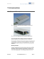
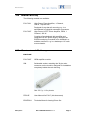
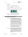
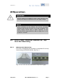
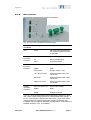
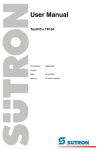
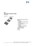
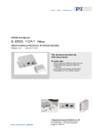
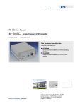
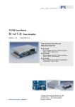
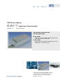
PZ201E User Manual E-617 Release: 1.1.1 High-Power Piezo Amplifier Date: 2010-04-21 This document describes the following product(s): E-617.001 High-Power Piezo Amplifier with Energy Recovery, 1 Channel, 100 W, Top-Hat Rail E-617.00F High-Power Piezo Amplifier with Energy Recovery, OEM Module, 1 Channel, 100 W © Physik Instrumente (PI) GmbH & Co. KG Auf der Römerstr. 1 ⋅ 76228 Karlsruhe, Germany Tel. +49-721-4846-0 ⋅ Fax: +49-721-4846-299 [email protected] ⋅ www.pi.ws Physik Instrumente (PI) GmbH & Co. KG is the owner of the following company names and trademarks: PI®, PIC®, PICMA®, PILine®, PIFOC®, PiezoWalk®, NEXACT®, NEXLINE®, NanoCube®, NanoAutomation® The following designations are protected company names or registered trademarks of third parties: Microsoft, Windows, LabView The products described in this document are in part protected by the following patents: Hyperbit™ (U.S. Patent 6,950,050) Copyright 2010 by Physik Instrumente (PI) GmbH & Co. KG, Karlsruhe, Germany. The text, photographs and drawings in this manual enjoy copyright protection. With regard thereto, Physik Instrumente (PI) GmbH & Co. KG reserves all rights. Use of said text, photographs and drawings is permitted only in part and only upon citation of the source First printing 2010-04-21, bsc, bro Document Number PZ201E, Release 1.1.1 E-617_User_PZ201E111.doc Subject to change without notice. This manual is superseded by any new release. The newest release is available for download at www.pi.ws (http://www.pi.ws). Disposal In accordance with EU directive 2002 / 96 / EC (WEEE), as of 13 August 2005, electrical and electronic equipment may not be disposed of in the member states of the EU mixed with other wastes. To meet the manufacturer’s product responsibility with regard to this product, Physik Instrumente (PI) GmbH & Co. KG will ensure environmentally correct disposal of old PI equipment that was first put into circulation after 13 August 2005, free of charge. If you have such old equipment from PI, you can send it to the following address postage-free: Physik Instrumente (PI) GmbH & Co. KG Auf der Römerstr. 1 76228 Karlsruhe, Germany Declaration of Conformity according to ISO / IEC Guide 22 and EN 45014 Manufacturer: Manufacturer´s Address: Physik Instrumente (PI) GmbH & Co. KG Auf der Römerstrasse 1 D-76228 Karlsruhe, Germany The manufacturer hereby declares that the product Product Name: Model Numbers: Product Options: Low-Voltage Piezo Amplifier/ Controller Module E-617.001 all complies with the following European directives: 2006/95/EC, Low Voltage Directive 2004/108/EC, EMC-Directive 98/37/EG,Machinery Directive The applied standards certifying the conformity are listed below. Electromagnetic Emission: EN 61000-6-3, EN 55011 Electromagnetic Immunity: EN 61000-6-1 Safety (Low Voltage Directive) : EN 61010-1 February 12, 2008 Karlsruhe, Germany Dr. Karl Spanner President The E-617.00F OEM Module is intended to be integrated in other electrical equipment. It does not carry the CE emblem but will conform to the cited EMC Standards and normative documents providing the user ensures a compliant connection when implementing the total system. Possible necessary measures are installation of the component in a suitable shielded enclosure and usage of suitable connectors. About This Document Users of This Manual This manual is designed to help the reader to install and operate the E-617 High-Power Piezo Amplifier. It assumes that the reader has a fundamental understanding of motion control concepts, piezoelectric drives and applicable safety procedures. The manual describes the physical specifications and dimensions of the E-617 High-Power Piezo Amplifier as well as the installation procedures which are required to put the associated motion system into operation. This document is available as PDF file. Updated releases are available for download from www.pi.ws or by email: contact your Physik Instrumente Sales Engineer or write [email protected]. Conventions The notes and symbols used in this manual have the following meanings: DANGER Indicates the presence of high voltage (> 50 V). Calls attention to a procedure, practice or condition which, if not correctly performed or adhered to, could result in injury or death. CAUTION Calls attention to a procedure, practice, or condition which, if not correctly performed or adhered to, could result in damage to equipment. NOTE Provides additional information or application hints. Related Documents The hardware components which might be delivered with E-617 High-Power Piezo Amplifiers are described in their own manuals. All documents are available as PDF files.. For updated releases visit download section of the PI Website (www.pi.ws), contact your Physik Instrumente Sales Engineer or write [email protected]. ! Contents 1 Introduction 1.1 1.2 1.3 1.4 1.5 1.6 2 Product Description ....................................................................2 Prescribed Use...........................................................................3 Safety Precautions .....................................................................4 Model Survey .............................................................................5 Contents of Delivery ...................................................................5 Additional Components ..............................................................6 Operation 2.1 External Analog Signal Source ................................................ 13 External DC-Offset Potentiometer ........................................... 13 Combining External Signal Source & DC Offset ...................... 14 Computer Control & Hyperbit ................................................... 14 Technical Data 3.1 3.2 3.3 4 Front Elements ......................................................................... 10 32-Pin Main Connector ............................................................ 11 System Connection Summary.................................................. 12 Start-Up .................................................................................... 12 Monitoring the Output Voltage ................................................. 13 Modes of Operation..................................................................13 2.3.1 2.3.2 2.3.3 2.3.4 3 Mechanical Mounting ................................................................. 7 Connections ............................................................................... 8 Start-Up ...................................................................................... 9 Monitoring the Output Voltage ................................................... 9 E-617.00F OEM Amplifier Module............................................10 2.2.1 2.2.2 2.2.3 2.2.4 2.2.5 2.3 15 Specifications ...........................................................................15 Operating Limits .......................................................................17 Block Diagram ..........................................................................18 Appendix 4.1 4.2 7 E-617.001 Amplifier Module for Top-Hat Rail Mounting.............7 2.1.1 2.1.2 2.1.3 2.1.4 2.2 2 19 Lifetime of PICMA® Actuators .................................................19 How to Measure the Amplifier Output ......................................21 Introduction 1 Introduction 1.1 Product Description Fig. 1: E-617.001 high-power piezo amplifier for top-hat rail mounting Fig. 2: E-617.00F high-power piezo amplifier OEM module E-617 high-power piezo amplifier modules are designed for dynamic operation of low-voltage piezoelectric translators. The innovative, efficient circuitry reduces power consumption and heat dissipation, especially in dynamic applications. This makes possible peak output currents up to 2000 mA and a peak power of 280 W. Working Principle Charge is transferred to the piezo actuator using low-loss PWM techniques. When the actuator is discharged, the energy not consumed is fed through the energy recovery circuitry for reuse in the next charging cycle. The working principle of the E-617 www.pi.ws E-617 PZ201E Release 1.1.1 Page 2 Introduction series is ideally suited for high-dynamics scanning and switching applications. Open-Loop and Closed-Loop Piezo Operation For open-loop piezo operation, the amplifier output voltage is determined by the analog signal at the Control Input combined with an optional DC-offset potentiometer setting. Open-loop operation is ideal for applications where the fastest response and the highest bandwidth are essential, but where commanding and reading the target position absolutely is either not important or is carried out in an external feedback loop. 1.2 Prescribed Use Based on their design and realization, the E-617 High-Power Piezo Amplifiers are intended to drive capacitive loads, in the present case, piezoceramic actuators. The E-617 must not be used for applications other than stated in this manual, especially not for driving ohmic (resistive) or inductive loads. Observe the safety precautions given in this User Manual. Operation other than instructed in this Manual may affect the safeguards provided. E-617s meet the following minimum specifications for operation * : Indoor use only Altitude up to 2000 m Ambient temperature from 5°C to 40°C Relative humidity up to 80% for temperatures up to 31°C, decreasing linearly to 50% relative humidity at 40°C Line voltage fluctuations of up to ±10% of the line voltage Transient overvoltages as typical for public power supply Note: The nominal level of the transient overvoltage is the standing surge voltage according to the overvoltage category II (IEC 60364-4-443). Degree of pollution: 2 * Any more stringent specifications in the Technical Data table are, of course, also met. www.pi.ws E-617 PZ201E Release 1.1.1 Page 3 Introduction 1.3 Safety Precautions DANGER—Read This Before Operation E-617 modules are amplifiers generating HIGH VOLTAGES for driving piezoelectric actuators. The output power may cause serious injuries. When working with these devices or using PZT products from other manufacturers we strongly advise you to follow general accident prevention regulations. Allow operation of the E-617.00F module only after it has been installed in a proper housing which provides protection against the exposed conductors with high voltages. All work done with and on the modules described here requires adequate knowledge and training in handling High Voltages. Be sure to connect pin 32a/c (E-617.00F) or the housing (E-617.001) to a Protective Ground WARNING E-617s need to be installed in such a way that they can quickly and easily be separated from the supply voltage. CAUTION—Electrostatic Hazard Electronic components are sensitive to electrostatic electricity. Take appropriate electrostatic protection measures when handling modules. www.pi.ws E-617 PZ201E Release 1.1.1 Page 4 ! Introduction 1.4 Model Survey The following models are available: E-617.001 High-Power Piezo Amplifier, 1 Channel, 100 W, Top-Hat Rail Designed for top-hat rail mounting e.g. in a switchboard in industrial automation processes. E-617.00F High-Power LVPZT Piezo Amplifier, OEM, 1 Channel, 100 W Consists of a mainboard with amplifier and integrated DC-DC power supply, designed as EURO-board plug-in module to be installed in a suitable enclosure, e.g. in a desktop or 19"-rackmount chassis. 1.5 Contents of Delivery E-617.00F E-617.00F OEM amplifier module 588 Solderable socket, matching the 32-pin main connector on the module, designed for installation completely inside the user housing. See 2.2.2, p.11 for pinouts. www.pi.ws PZ201E User Manual for E-617 (this document) E500T0011 Technical Note for Analog Driver Set E-617 PZ201E Release 1.1.1 Page 5 Introduction E-617.001 E-617.001 Top-Hat-Rail Amplifier module 000019731 IMC1,5/3-ST-3,81 3-pin Mini-Combicon connector 000019728 MC1,5/6-ST-3,81 6-pin Mini-Combicon connector 000019727 MC1,5/3-ST-3,81 3-pin Mini-Combicon connector Phoenix Mini-Combicon connectors 1.6 PZ201E User Manual for E-617 (this document) E500T0011 Technical Note for Analog Driver Set Additional Components www.pi.ws E-500.ACD CD with LabVIEW analog driver set, available free of charge upon request. (Driver set can also be downloaded from www.pi.ws: see included technical note E500T0011 for instructions). The E-617 can be controlled via a signal connected to its analog input line (see "Using the Analog Input" for more information). This signal can, for example, be generated using a D/A board in a PC. PI offers a LabVIEW driver set which can be used with certain D/A boards. It is compatible with the PI General Command Set (GCS) LabVIEW driver set available for all newer controllers from PI. The PI LabVIEW drivers support all D/A converter boards from National Instruments that are compatible with DAQmx8.3. LabVIEW compatibility is given from version 7.1 upwards. E-500.HCD Access to HyperBit Functionality for Enhanced System Resolution (Supports certain D/A boards). PI’s patented Hyperbit technology for providing position resolution higher than that of the D/A board is in the E-500.ACD driver set. Activating Hyperbit requires purchase of a password, which can be obtained from PI under Order No. E500.HCD. E-617 PZ201E Release 1.1.1 Page 6 Operation 2 Operation WARNING E-617s need to be installed in such a way that they can quickly and easily be separated from the supply voltage. NOTE When powering up the module, the DC-DC converter needs a peak current of about 3 A to start oscillating. The power supply should have a buffer capacitor, or the external power supply should be able to supply the 3 A for at least 0.1 second. 2.1 E-617.001 Amplifier Module for TopHat Rail Mounting 2.1.1 Mechanical Mounting E-617.001 is designed to be mounted on a standard 35 mm tophat mounting rail (DIN EN 50022). See Fig. 3. Fig. 3: E-617.001 rear view with detail of top-hat rail (right) www.pi.ws E-617 PZ201E Release 1.1.1 Page 7 Operation 2.1.2 Connections All electrical connections are on the front panel. Fig. 4: E-617.001 connectors (Phoenix lugs) Element / Connector Labeling Description LED Power The green LED indicates that the module is powered up and in operation. Supply Input / +24 V (23 to 26 V) 3-pin Mini0V Combicon GND Control / 6-pin MiniCombicon Output / 3-pin MiniCombicon Unipolar supply voltage Supply voltage GND Protective ground Control In -2 to 12 V* Control input voltage AGND GND PZT Monitor Monitor voltage 1:100 -10 V Ref / Pot CW Optional potentiometer, CW connection Pot Wiper Optional potentiometer, wiper connection AGND / Pot CCW Optional potentiometer, CCW connection PZT Out -30 to 130 V* Piezo output voltage PGND GND Shield Protective Ground *-2 to 12 V is the recommended control input range, resulting in -20 to 120 V piezo output voltage (without DC-offset potentiometer usage). -3 to 13 V control input are possible and will result in -30 to 130 V output voltage (without DC-offset potentiometer usage), but working with increased output voltage will decrease actuator lifetime. See “Lifetime of PICMA® Actuators” on p. 19 for details. www.pi.ws E-617 PZ201E Release 1.1.1 Page 8 Operation 2.1.3 Start-Up On the main board of the E-617 modules a DC-DC converter is installed with a 23 to 26 VDC input voltage range. The converter generates -30 and +130 V for the power amplifier. 1 Optionally, connect an external 10 k-ohm potentiometer to the control input sockets using the included 6-pin connector. Turn it to zero offset (CCW) to avoid jumps of the mechanics when the amplifier is powered on. 2 Supply the board with the 24 VDC power at the 3 Power input sockets using the included 3-pin connector. The green power-on LED on the front should light up. Check the output voltage on the output lines without an actuator connected. The internal power supply has a soft start, it takes a few seconds (2 to 5 s) to get a stable output voltage. In this time the Control Input should be 0V. 3 If you have connected the optional external potentiometer to offset the control input range, then it can be used to check the output voltage. Varying the offset from 0 to +10 V should make the output vary from 0 to +100 V. 4 If no external potentiometer is connected, drive the control input with a control voltage in the range of -2 to +12 V. The corresponding output range should be -20 to +120 V. Most dynamic applications require the power amplifier to deliver a short peak current higher than an average value. Because of the limited power of the transistors, this peak is limited to about 5 ms in length. After this time the current decreases to the average value. 2.1.4 Monitoring the Output Voltage The PZT drive voltage is proportional to the analog signal input in combination with the position of the DC offset potentiometer, if installed. The PZT output voltage can be monitored either directly (in parallel with the PZT) or on the front-panel connector, which carries a high-impedance output of 1/100th the voltage of the PZT. www.pi.ws E-617 PZ201E Release 1.1.1 Page 9 Operation 2.2 E-617.00F OEM Amplifier Module DANGER All work done with and on this module requires adequate knowledge and training in handling High Voltages. Allow operation of the E-617.00F module only after it has been installed in a proper housing which provides protection against the exposed conductors with high voltages. Be sure to connect pin 32a/c to a protective ground This module consists of a mainboard with amplifier and integrated DC-DC power supply, designed as EURO-board plugin module which can be installed in a desktop chassis as well as in a 19"-rack-mount chassis. 2.2.1 Front Elements Fig. 5: E-617.00F front elements LED lights green for operation Control Input SMB socket, -2 to +12 V (also on pin 10c of the 32-pin main connector; use only one of the connections)* PZT Out LEMO connector, -30 to 130 V output* *-2 to 12 V is the recommended control input range, resulting in -20 to 120 V piezo output voltage (without DC-offset potentiometer usage). -3 to 13 V control input are possible and will result in -30 to 130 V output voltage (without DC-offset potentiometer usage), but working with increased output voltage will decrease actuator lifetime. See “Lifetime of PICMA® Actuators” on p. 19 for details. www.pi.ws E-617 PZ201E Release 1.1.1 Page 10 Operation 2.2.2 32-Pin Main Connector All inputs and outputs are available on the main connector. Because the DIN 41612 connector standard includes types with more pins, the 32 pins all carry even number designations and are in rows “a” and “c”. NOTE The inputs and outputs of the DC-DC converter are not connected internally. Using a unipolar power supply, we recommend connecting the negative supply at pin 18a,c with the GND at pin 20a,c. This provides a defined GND level and helps to minimize noise. Function Function PZT output a 2 c PZT output PZT GND a 4 c PZT GND Sync Input TTL Signal, 200 kHz, a input impedance 5.1 kΩ, 470 pF 6 c Control Out include Offset Signal OUT Monitor PZT out (100:1) a 8 c Amplifier In OVN status signal (output) a 10 c Control In (also on SMB socket; use only one of the connections) 10 kOhm pot (-10 V) a 12 c Pot wiper 10 kOhm pot (GND) & AGND a 14 c 10 kOhm pot (GND) & GND +VCC supply, +24 V a 16 c +VCC supply, +24 V -VCC supply, 0 V a 18 c -VCC supply, 0 V (connect to 20c for minimum noise) AGND a 20 c AGND nc a 22 c AGND nc a 24 c nc nc a 26 c nc nc a 28 c nc nc a 30 c nc Protective GND a 32 c Protective GND nc = not connected www.pi.ws E-617 PZ201E Release 1.1.1 Page 11 Operation 2.2.3 System Connection Summary For operation, at least the following elements must be connected (pin numbers refer to the 32-pin main connector): 2.2.4 Supply power, 24 VDC + 16a&c; – 18a&c PZT out 2 a&c PZT GND 4a&c Control out to Amplifier In 6c to 8c (e.g. short these pins) Control In 10c or SMB socket (use only one of the connections) DC-offset pot 12a (-10 V) & 12c (pot wiper) & 14a (AGND) GND 22c, 20a&c, 14a&c Protective GND 32a&c Start-Up On the main board of the E-617.00F module a DC-DC converter is installed with a 23 to 26 VDC input voltage range. The converter generates -37 and +137 V for the power amplifier. www.pi.ws 1 Connect pin 6c (control out) to pin 8c (amplifier in). 2 Optionally connect an external 10 k-ohm potentiometer to 12a, 12c and 14a. Turn it to zero offset (CCW) to avoid jumps of the mechanics when the amplifier is powered on. 3 Supply the board with 24 VDC power at pins 16a/c and 18a/c. The green power-on LED on the base of the board should light up. Check the output voltage between main connector pins 2a/c and 4a/c without an actuator connected. The internal power supply has a soft start, it takes a few seconds (2 to 5 s) to get a stable output voltage. In this time the Control Input should be 0V. 4 If you have connected the optional external potentiometer to offset the control input range, then it can be used to check the output voltage. Varying the offset from 0 to +10 V should make the output vary from 0 to +100 V. E-617 PZ201E Release 1.1.1 Page 12 Operation 5 If no external potentiometer is connected, drive the control input (either pin 10c or SMB socket) with a control voltage in the range of -2 to +12 V. The corresponding output range should be -20 to +120 V. Most dynamic applications require the power amplifier to deliver a short peak current higher than an average value. Because of the limited power of the transistors, this peak is limited to about 5 ms in length. After this time the current decreases to the average value. 2.2.5 Monitoring the Output Voltage The PZT drive voltage is proportional to the analog signal input in combination with the position of the DC offset potentiometer, if installed. The PZT output voltage can be monitored either directly (in parallel with the PZT) or on main connector pin 8a, which carries a high-impedance output of 1/100th the voltage of the PZT. 2.3 Modes of Operation All units are operated as simple power amplifiers, where the PZT output voltage depends directly on the input control voltage and the DC offset, if any. This is also known as open-loop or servo-off operation. 2.3.1 External Analog Signal Source For external operation, the output voltage is controlled by an external DC signal in the range of -2 to +12 V (-3 to +13 V are possible but working with increased output voltage will decrease actuator lifetime, see p. 19 for details). See section 2.3.4, p.14, for information on PI support of external operation with a DAC card in a PC. 2.3.2 External DC-Offset Potentiometer In manual operation, the target voltage is controlled manually with an external 10 kΩ DC-offset potentiometer (not included). E-617.001: The potentiometer must be connected to the proper sockets, see Section 2.1.2, p. 8. E-617.00F: The potentiometer must be connected to pin 12a (CW), 14a (CCW), and the wiper to pin 12c. www.pi.ws E-617 PZ201E Release 1.1.1 Page 13 Operation 2.3.3 Combining External Signal Source & DC Offset For external operation with offset, the offset potentiometer (or equivalent) is attached and an external DC signal is used on Control IN. Control input signal and the signal from the external DC-offset potentiometer are combined in the preamplifier stage. The resultant signal will be used as input for the amplifier and must be in the -2 to +12 V range (-3 to +13 V are possible but working with increased output voltage will decrease actuator lifetime, see p. 19 for details). Note that instead of connecting an DC-offset potentiometer, you can connect an external DC signal in the range of -10 to 0 V to the pot wiper connection. This signal can be used as analog control input in addition to the Control IN signal. 2.3.4 Computer Control & Hyperbit Computer control of an E-617 can be realized using a DACboard in a PC to generate the analog input signal. PI offers a LabVIEW driver set which can be used with certain D/A boards. This driver set is compatible with the PI General Command Set (GCS) LabVIEW driver set available for all newer controllers from PI. The Analog Controller LabVIEW Driver (E-500.ACD) is free of charge, but requires the LabVIEW environment from National Instruments for operation. In addition, PI’s patented Hyperbit technology for providing position resolution higher than that of the D/A board is available for purchase as an option (E500.HCD). The PI Analog Controller and Hyperbit drivers support all D/A converter boards from National Instruments that are compatible with DAQmx8.3. LabVIEW compatibility is given from version 7.1 upwards. Instructions for downloading the Analog Controller drivers is given in included Technical Note E500T0011; the drivers can also be obtained on CD as E500.ACD. www.pi.ws E-617 PZ201E Release 1.1.1 Page 14 Technical Data 3 Technical Data 3.1 Specifications Model E-617.001 E-617.00F Function High-Power Piezo Amplifier with Energy Recovery, 1 Channel, Top-Hat Rail High-Power Piezo Amplifier with Energy Recovery, 1 Channel, OEM Module Tolerance Input voltage Output voltage Peak power Average output power -2 to +12 V* -30 to 130 V* 280 VA Corresponds to up to 100 VA reactive power -2 to +12 V* -30 to 130 V* 280 VA Corresponds to up to 100 VA reactive power Peak current 2000 mA 2000 mA <5 ms Average output current Current limits 700 mA Short-circuit-proof 700 mA Short-circuit-proof >5 ms Voltage constants Small-signal bandwidth Ripple, noise, 0 to 100 kHz 10 ±0.1 3.5 kHz <5mVrms / 10kHz <20mVpp / 10kHz <30 mVrms / 100kHz <100 mVpp / 100kHz 1.0 µF 10 ±0.1 3.5 kHz <5mVrms / 10kHz <20mVpp / 10kHz <30 mVrms / 100kHz <100 mVpp / 100kHz 1.0 µF >2 µF 0.5 Ω <1 mV Class D, switching amp, (100 kHz) 100 kΩ >2 µF 0.5 Ω <1 mV Class D, switching amp (100 kHz) 100 kΩ Phoenix-plug connector MINI-COMBICON 3-pin MC1.5/3-ST-3.81 Phoenix-plug connector MINI-COMBICON 6-pin IMC1.5/6-ST-3.81 0 to 100 V at output with external pot (not included) LEMO ERA.00.250.CTL (front), DIN 41612, 32-pin (rear) SMB Amplifier Base load (internal)** Reasonable piezo load** Output impedance Amplifier step resolution Amplifier type Input impedance Interfaces and Operation Piezo connector Analog / Control IN socket DC-Offset Setting www.pi.ws Max. Max. 0 to 100 V at output with external pot (not included) E-617 PZ201E Release 1.1.1 Page 15 Technical Data Model Miscellaneous E-617.001 E-617.00F Tolerance Operating temperature range Dimensions Mass Operating voltage +5 to +50 °C (10% derated over 40 °C) 205 x 105 x 60 mm 1 kg 23 to 26 VDC, stabilized, on Phoenix plug MINICOMBICON 3-pin IMC1.5/3-ST-3.81 +5 to +50 °C (10% derated over 40 °C) 7HP/3U 0.35 kg 23 to 26 VDC, stabilized on 32-pin. DIN 41612 rear connector Power consumption <30 W <30 W Max. * -2 to 12 V is the recommended control input range, resulting in -20 to 120 V piezo output voltage (without DC-offset potentiometer usage). -3 to 13 V control input are possible and will result in -30 to 130 V output voltage (without DC-offset potentiometer usage), but working with increased output voltage will decrease actuator lifetime. See “Lifetime of PICMA® Actuators” on p. 19 for details. ** The internal base load is required to obtain a stable amplifier output voltage when no external piezo load is connected. Note that the amplifier output power is allocated to the internal and external loads according to their capacitance values. This is of particular importance under large-signal conditions. Examples: The small-signal capacitance of the connected piezo actuator is 550 nF, hence its large-signal capacitance is approx. 1.1 µF (2 * 550 nF). Under large-signal conditions, 50 W will be allocated to the internal base load (1 µF), while approx. 55 W will be available for the external piezo load. With a small-signal capacitance of 1 µF, the piezo actuator would have a large-signal capacitance of 2 µF, and approx. 67 W would be available for it. www.pi.ws E-617 PZ201E Release 1.1.1 Page 16 Technical Data 3.2 Operating Limits Fig. 6: E-617 open-loop frequency response with various PZT loads. Values shown are capacitance in μF. www.pi.ws E-617 PZ201E Release 1.1.1 Page 17 Technical Data 3.3 Block Diagram Fig. 7: E-617 wiring. Pin numbers for E-617.00F are given in the drawing (see section 2.2.2, p.11, for pin assignments). Control input signals (for E-617.00F: on main connector pin 10c) and the signal from the external DC-offset potentiometer are combined in the preamplifier stage. The resultant signal will be used as input for the amplifier. With E-617.001, CONTROL OUT and AMPLIFIER IN are interconnected internally. www.pi.ws E-617 PZ201E Release 1.1.1 Page 18 Appendix 4 Appendix 4.1 Lifetime of PICMA® Actuators The following factors which can have an impact on the actuator lifetime must be taken into consideration: Applied voltage, temperature and relative humidity. The effect of each individual factor on the lifetime can be read off the diagrams shown below. The lifetime calculated in hours simply results as the product of all three values read off the diagrams. The impact that the applied voltage has, is particularly important. With decreasing voltage the lifetime increases exponentially. This must always be taken into consideration in an application. The recommended maximum range of the control input voltage for E-617 therefore is -2 to 12 V, resulting in a piezo voltage range of -20 to 120 V. A control input range of -3 to 13 V is possible (results in -30 to 130 V piezo voltage), but will reduce the actuator lifetime accordingly. Fig. 8: Interdependency between the mean MTTF of a PICMA® actuator and the value of the voltage applied www.pi.ws E-617 PZ201E Release 1.1.1 Page 19 Appendix Fig. 9: Interdependency between the mean MTTF of a PICMA® actuator and the ambient temperature Fig. 10: Interdependency between the mean MTTF of a PICMA® actuator and the relative humidity Example The simple formula MTTF = AU * AT * AF provides a quick estimate of the reliability in hours. In concrete terms: The values for 75% RH ( AF=14), 100 VDC (AU=75) and 45 °C (AT=100) result in an approximate MTTF of 105,000 h, i.e. more than 11 years (see markings on the diagrams). Read the “Tutorial: Piezoelectrics in Positioning” in the PI Catalog for detailed information. www.pi.ws E-617 PZ201E Release 1.1.1 Page 20 Appendix 4.2 How to Measure the Amplifier Output The innovative, efficient circuitry of the E-617 reduces power consumption and heat dissipation, especially in dynamic applications. Working with an internal switching frequency of 100 kHz, charge is transferred to the piezo actuator using lowloss PWM techniques. The ripple of the amplifier output is <100 mVpp at 100 kHz. But when measuring the amplifier output signal with low sampling rate and small bandwidth (e.g. with a digital oscilloscope), aliasing will occur and distort the measurement result. In digital signal processing, aliasing refers to an effect that the signal reconstructed from samples is different than the original continuous signal when the sampling rate is too low. With the E-617 amplifier output, this means that a lowfrequency signal seems to be measured which is not present at all. Example: When a 91 Hz signal is sampled with 100 Hz sampling rate, the result seems to be a 9.1 Hz signal (see figure below). Fig. 11: Signal digitization with too low sample rate (time in 1/100 s): Original signal = 91 Hz and sampling rate = 100 Hz; the result is mistaked as a 9.1 Hz signal (“Alias”) To avoid aliasing, the sampling rate must be at least twice as high as the highest frequency in the signal to be sampled (according to the Nyquist–Shannon sampling theorem). I.e. with an amplifier switching frequency of 100 kHz, the sampling rate must be 200 kHz or higher. If the sampling rate provided by your oscilloscope is not high enough, use a low-pass filter at the oscilloscope input to eliminate frequencies above 100 kHz. Alternatively, you can use an analog oscilloscope or perform high-resolution measurements in the lower frequency range. When following those instructions, you will obtain valid measurement results. www.pi.ws E-617 PZ201E Release 1.1.1 Page 21