1
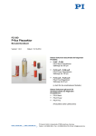
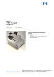
PZ210E User Manual
E-462 Piezo Amplifier
Release: 1.1.0 Date: 20 July 2011
This document describes the following
products:
■
E-462.00
HVPZT Piezo Amplifier, 10 to 1000 V, Bench Top
■
E-462.OE1
HVPZT Piezo Amplifier Module, 10 to 1000 V,
OEM-Version
© Physik Instrumente (PI) GmbH & Co. KG
Auf der Römerstr. 1 ⋅ 76228 Karlsruhe, Germany
Tel. +49 721 4846-0 ⋅ Fax: +49 721 4846-1019
[email protected] ⋅ www.pi.ws
Physik Instrumente (PI) GmbH & Co. KG is the owner of the following company names and trademarks:
PI®, PIC®, PICMA®, PILine®, PIFOC®, PiezoWalk®, NEXACT®, NEXLINE®, NanoCube®,
NanoAutomation®
The following designations are protected company names or registered trademarks of third parties:
LabVIEW
The products described in this manual are in part protected by the following patents:
US-Patent No. 6,950,050
Copyright 1999–2011 by Physik Instrumente (PI) GmbH & Co. KG, Karlsruhe, Germany.
The text, photographs and drawings in this manual enjoy copyright protection. With regard thereto,
Physik Instrumente (PI) GmbH & Co. KG reserves all rights. Use of said text, photographs and drawings
is permitted only in part and only upon citation of the source.
Document Number PZ210E BSc, BRo, Release 1.1.0
E-462_User_PZ210E110.doc
Subject to change without notice. This manual is superseded by any new release. The newest release is
available for download at www.pi.ws (http://www.pi.ws).
Declaration of
Conformity
according to ISO / IEC Guide 22 and EN 45014
Manufacturer:
Manufacturer´s
Address:
Physik Instrumente (PI)
GmbH & Co. KG
Auf der Römerstrasse 1
D-76228 Karlsruhe,
Germany
The manufacturer hereby declares that the product
Product Name:
Piezo Amplifier
Model Numbers:
E-462
Product Options:
all
complies with the following European directives:
2006/95/EC, Low-voltage directive
2004/108/EC, EMC Directive
The applied standards certifying the conformity are listed below.
Electromagnetic Emission:
EN 61000-6-3, EN 55011 (05/98)+
A1(08/99) class A,
EN 55022 ( 09/98)
Electromagnetic Immunity:
EN 61000-6-1
Safety (Low Voltage Directive):
EN 61010-1
April 4, 2008
Karlsruhe, Germany
Dr. Karl Spanner
President
About this Document
Users of This Manual
This manual is designed to help the reader to install and operate the E-462 Piezo Amplifier. It assumes
that the reader has a fundamental understanding of motion control concepts and applicable safety
procedures.
The manual describes the physical specifications and dimensions of the E-462 Piezo Amplifier as well.
Conventions
The notes and symbols used in this manual have the following meanings:
WARNING
Calls attention to a procedure, practice or condition which, if not
correctly performed or adhered to, could result in injury or death.
DANGER
Indicates the presence of high voltage (> 50 V). Calls attention to a
procedure, practice or condition which, if not correctly performed or
adhered to, could result in injury or death.
CAUTION
Calls attention to a procedure, practice, or condition which, if not
correctly performed or adhered to, could result in damage to
equipment.
NOTE
Provides additional information or application hints.
Any optional elements which might be mentioned in this documentation are described in their own
manuals. Current releases can be downloaded from the PI Website as PDF files (www.pi.ws
(http://www.pi.ws)). Updated releases are available for download from www.pi.ws or by email: contact
your Physik Instrumente Sales Engineer or write [email protected]..
!
Contents
1
Introduction
1.1
1.2
1.3
1.4
1.5
2
Overview............................................................................................ 2
Prescribed Use .................................................................................. 2
Safety Precautions............................................................................. 3
Unpacking.......................................................................................... 4
Computer Control .............................................................................. 5
Start-Up
2.1
6
E-462.00 ............................................................................................ 6
2.1.1
2.1.2
2.1.3
2.1.4
2.2
2
Front and Rear Panel Elements ........................................................... 7
Control Signal ....................................................................................... 8
Starting Operation ................................................................................. 8
Power Supply for E-462.00 ................................................................... 9
E-462.OE1 ....................................................................................... 10
2.2.1
2.2.2
2.2.3
Connections ........................................................................................ 10
Dimensions ......................................................................................... 11
Control Signal ..................................................................................... 11
3
Customer Service
13
4
Disposal
14
5
Technical Data
15
5.1
5.2
Specifications .................................................................................. 15
Connectors ...................................................................................... 16
5.2.1
5.2.2
5.2.3
High-Voltage Connector ..................................................................... 16
Control Input ....................................................................................... 16
Supply Power Connector .................................................................... 16
Introduction
1
Introduction
1.1
Overview
The E-462.00 piezo driver is a low-cost amplifier/driver for PICA
high-voltage PZTs. It can output a peak current of 0.5 mA and is specially
designed for static and quasi-static applications.
Analog Control
E-462 amplifiers are designed to provide precise control of open-loop piezo
positioning systems. The amplifier output voltage is determined by an
analog control signal.
PCB-Mount Version for OEMs
The E-462.OE1 version is fully enclosed in a metal case and designed for
mounting on circuit boards. All input connections are via 6 header pins
located on the bottom. The PZT (piezo) high voltage output is via a coaxial
cable with LEMO connector.
If dynamic (>1 Hz) PZT operation is required, please consider instead the
E-464 (3-channel bench-top amplifier), E-470 or E-508 amplifiers (modular
systems with sensor/servo option).
1.2
Prescribed Use
Based on their design and realization, E-462 Piezo Amplifiers are intended
to drive capacitive loads, in the present case, piezoceramic actuators.
E-462s must not be used for applications other than stated in this manual,
especially not for driving ohmic (resistive) or inductive loads.
www.pi.ws
E-462 PZ210E Release 1.1.0
Page 2
Introduction
Observe the safety precautions given in this User Manual.
The E-462 is a laboratory apparatus as defined by DIN EN 61010. It meets
the following minimum specifications for safe operation (any more stringent
specifications in the technical data table are, of course, also met):
■
■
■
■
■
■
■
1.3
Indoor use only
Altitude up to 2000 m
Temperature range 5°C to 40°C
Max. relative humidity 80% for temperatures up to 31°C, decreasing
linearly to 50% relative humidity at 40°C
Line voltage fluctuations not greater than ±10% of the line voltage
Transient overvoltages as typical for public power supply
Note: The nominal level of the transient overvoltage is the standing
surge voltage according to the overvoltage category II (IEC
60364-4-443).
Degree of pollution: 2
Safety Precautions
Carefully read also the user manuals and/or technical notes of all other
components involved, such as controllers or software.
Failure to heed warnings in this manual can result in bodily injury or
material damage.
DANGER—IMPROPER WIRING
E-462 Power Amplifiers output VERY HIGH VOLTAGES and HIGH
CURRENTS which can cause death or injury!
Take special care if connecting products from other manufactures.
Follow general accident prevention rules!
Working with these devices requires adequately trained and educated
operating personnel.
During operation, do NOT touch any part which might be connected to
the PZT HV output!
Make sure that your actuator (or actuator cable shield) is connected to
a protective earth conductor.
www.pi.ws
E-462 PZ210E Release 1.1.0
Page 3
Introduction
DANGER—IMPROPER WIRING
Improper wiring of HIGH VOLTAGE connectors can cause death, injury
or damage. Modification of HIGH VOLTAGE connectors should only be
carried out by the manufacturer. Any unauthorized modification may
jeopardize operating personnel. Treat HIGH VOLTAGES and HIGH
CURRENTS with respect.
CAUTION
Exposing some PZTs to voltages too far outside their operating range
will destroy the active element in the actuator. Make sure that both the
polarity and the voltage as seen by the PZT are within the allowable
range.
!
Be especially vigilant regarding polarity when using older actuators,
adapter cables and controllers set up for non-standard voltage ranges.
CAUTION
Read this before operating the equipment covered in this manual.
Always keep the User Manual safe and close to the described device.
In case of loss or damage to the instructions, please order a new copy
from your PI distributor or download one from www.pi.ws
(http://www.pi.ws). Also keep and add all further information (e.g.
extended instructions or Technical Notes) to the User Manual.
1.4
Unpacking
Unpack the E-462 Piezo Amplifier with care. Compare the contents against
the items covered by the contract and against the packing list.
The following components are included:
E-462
Piezo amplifier as ordered
E-660.PS
Wall-plug power supply. With E-462.00 only.
PZ210
User manual for E-462
E500T0011
Technical Note for Analog Driver Set
Inspect the contents for signs of damage. If parts are missing or you notice
signs of damage, contact PI immediately.
Save all packing materials in case the product need be shipped again.
www.pi.ws
E-462 PZ210E Release 1.1.0
Page 4
!
Introduction
1.5
Computer Control
Optionally, the control input voltage can be provided by a D/A converter.
For several D/A boards from National Instruments, PI offers a
corresponding LabVIEW driver set which is compatible with the PI General
Command Set (GCS), the command set used by all PI controllers. A further
option includes the patented Hyperbit technology providing enhanced
system resolution.
E-500.ACD
CD with Driver Set for Analog Controllers, available on
free CD on request or for download. See the included
E500T0011 Technical Note for details.
Computer control can be implemented using a DAC
board in a PC to generate the analog input signal. PI
offers a LabVIEW driver set which can be used with
certain D/A boards. This driver set is compatible with
the PI General Command Set (GCS) LabVIEW driver
set available for all newer controllers from PI.
The PI LabVIEW drivers support all D/A converter
boards from National Instruments that are compatible
with DAQmx8.3. LabVIEW compatibility is given from
version 7.1 upwards.
E-500.HCD
www.pi.ws
Access to HyperBit Functionality for Enhanced System
Resolution (Supports certain D/A boards)
PI’s patented Hyperbit technology for providing position
resolution higher than that of the D/A board is in the
E-500.ACD driver set. Activating Hyperbit requires
purchase of the password, which can be obtained from
PI under Order No. E-500.HCD.
E-462 PZ210E Release 1.1.0
Page 5
Start-Up
2
Start-Up
WARNING—INPUT POWER
E-462s need to be installed in such a way that they can quickly and
easily be separated from their input power source.
NOTE
The E-462.00 and E-462.OE1 are not equipped with active discharge
circuitry but have a 5·M-ohm, 3.9·nF RC network. Therefore, PZT
charge and discharge times will differ.
Installation and startup procedure depends on whether the E-462.00 or the
E-462.OE1 is concerned.
2.1
E-462.00
DANGER—HIGH VOLTAGE
E-462 Power Amplifiers output VERY HIGH VOLTAGES and HIGH
CURRENTS which can cause death or injury!
Take special care if connecting products from other manufactures.
Follow general accident prevention rules!
Working with these devices requires adequately trained and educated
operating personnel.
During operation, do NOT touch any part which might be connected to
the PZT HV output!
Make sure that your actuator (or actuator cable shield) is connected to
a protective earth conductor.
www.pi.ws
E-462 PZ210E Release 1.1.0
Page 6
Start-Up
2.1.1
Front and Rear Panel Elements
The E-462.00 piezo amplifier offers 1 channel with the following operating
elements on the front panel:
“DC-OFFSET” knob
1-turn potentiometer for DC offset (see
“Control Signal” p. 8)
“CONTROL INPUT” BNC
socket
Connection of control signal (see “Control
Signal” p. 8)
“PZT” LEMO socket
High-voltage output for PZT (see
“Connectors” p. 16)
Fig. 1: E-462 front and rear panels
The supply power connection is located on the rear panel.
12 V SUPPLY
www.pi.ws
Mini phone jack (tip positive) for connection
of included E-660.PS (see p. 9).
E-462 PZ210E Release 1.1.0
Page 7
Start-Up
2.1.2
Control Signal
Output voltage is controlled by an analog signal applied to the BNC input; it
plus the DC offset make up the Amplifier IN signal which must be in the 0 to
10 V range.
Control In Signal
An external voltage in the range of 0 to 10 V can be applied to the
“CONTROL INPUT” BNC socket.
DC Offset Potentiometer
Depending on the position of the “DC-OFFSET” knob, a DC voltage
between 0 and 10 V is made available. If you require a constant DC offset
(e.g. 0), make sure the knob stays at the required position.
2.1.3
Starting Operation
Observe the safety precautions (p. 3) given in this User Manual!
Proceed as follows.
www.pi.ws
1
With the E-462 powered down, connect the piezo actuator to the
HV output.
2
Turn the “DC-OFFSET” knob fully counterclockwise (CCW).
3
Make sure that voltage at “Control Input” is set to 0 V.
4
Connect the E-462 to supply power. The connection is on the rear
panel.
5
Command the first motion of the piezo actuator by turning the
“DC-OFFSET” knob fully clockwise (CW) to run the actuator over
the nominal travel range, then turn the knob back fully CCW
Make sure that the full voltage swing is attained
6
If an external analog signal is used, connect the signal source to
the “CONTROL INPUT” BNC socket. If the input signal range is not
0 to +10 V, use the “DC-OFFSET” knob to bias it accordingly. The
output signal will be 100 times the sum of the DC offset and the
control input.
E-462 PZ210E Release 1.1.0
Page 8
Start-Up
2.1.4
Power Supply for E-462.00
The E-462.00 bench top unit includes a wall-plug power supply (E-660.PS)
with interchangeable prong sets. Slide the appropriate prong set into the
body until it clicks in place. Note that to remove a prong set it is necessary
to press the plastic tab marked “Push”.
Fig. 2: E-660.PS with
Interchangeable prongs
www.pi.ws
E-462 PZ210E Release 1.1.0
Page 9
Start-Up
2.2
E-462.OE1
DANGER—HIGH VOLTAGE
E-462 Power Amplifiers output VERY HIGH VOLTAGES and HIGH
CURRENTS which can cause death or injury!
Take special care if connecting products from other manufactures.
Follow general accident prevention rules!
Working with these devices requires adequately trained and educated
operating personnel.
During operation, do NOT touch any part which might be connected to
the HV output!
Make sure that your actuator and pin 3 or 5 of the E-462.OE1 are
connected to a protective earth conductor.
Figure 1: E-462.OE1 OEM module has HV cable on top and pins on the
bottom (not shown) for PCB mounting
2.2.1
Connections
Observe the safety precautions (p. 3) when handling the E-462.OE1!
The piezo voltage output is on a short cable on the top side. The connector
is the standard LEMO socket PI uses for high-voltage piezo actuators (see
“Connectors” p. 16). With the unit powered down, connect the piezo
actuator to the LEMO socket.
The E-462.OE1 module is designed for PCB mounting. All connections
except for the piezo voltage output are made via the pins on the bottom
side.
www.pi.ws
E-462 PZ210E Release 1.1.0
Page 10
Start-Up
Connect pin 3 or 5 to a protective earth conductor.
Pin
1
2
3
4
5
6
Function
Supply Power (GND)
Supply Power 12 V DC ±10 %
GND
Output reference voltage +5 V
GND
Input control voltage, 0 to 5 V
Figure 2: E-462.OE1, top view, shown wired for manual operation with an external
potentiometer using the on-board 5 V DC reference voltage.
2.2.2
Dimensions
Figure 3: E-462.OE1, bottom view, dimensions in millimeters
2.2.3
Control Signal
Output voltage is controlled by an analog signal in the 0 to 5 V range. The
signal can be generated with one of the following options:
www.pi.ws
E-462 PZ210E Release 1.1.0
Page 11
Start-Up
■
■
www.pi.ws
Connect an external signal source to pins 5 and 6.
Interconnect pins 4, 5 and 6 via an external potentiometer as shown
in Figure 2 above. This option uses the 5 V DC reference available
on pin 4.
E-462 PZ210E Release 1.1.0
Page 12
Customer Service
3
Customer Service
Call your PI representative or write to [email protected]; please have the following
information about your system ready:
www.pi.ws
■
Product codes and serial numbers of all products in the system
■
Current firmware version of the controller (if present)
■
Version of drivers and / or host software (if present)
■
Operating system on host PC (if present)
E-462 PZ210E Release 1.1.0
Page 13
Disposal
4
Disposal
In accordance with EU directive 2002 / 96 / EC (WEEE), as of 13 August
2005, electrical and electronic equipment may not be disposed of in the
member states of the EU mixed with other wastes.
To meet the manufacturer’s product responsibility with regard to this
product, Physik Instrumente (PI) GmbH & Co. KG will ensure
environmentally correct disposal of old PI equipment that was first put into
circulation after 13 August 2005, free of charge.
If you have such old equipment from PI, you can send it to the following
address postage-free:
Physik Instrumente (PI) GmbH & Co. KG
Auf der Römerstr. 1
76228 Karlsruhe, Germany
www.pi.ws
E-462 PZ210E Release 1.1.0
Page 14
Technical Data
5
Technical Data
5.1
Specifications
Function
E-462.00
E-462.OE1
Power amplifier for PICA
high-voltage PZTs
Power amplifier for PICA
high-voltage PZTs
Units
1
10 to 1000
0.3
0.5
1
10 to 1000
0.3
0.5
V
W
W
0.3
0.3
mA
0.5
0.5
mA
Short-circuit-proof
50
50 (100 nF)
100 ±1
0 to +10
10
Static and quasi-static
applications only
Short-circuit-proof
50
50 (100 nF)
200 ±1
0 to +5
10
Static and quasi-static
applications only
LEMO
EGG.0B.701.CJL1173
BNC
1-turn pot., adds 0 to +10 V
to Control input
LEMO
PHG.0B.701.CJL1173 D42
Header pins
-
250 x 150 x 73
0.5
12 ±10 %
90
+5°C to +50°C (over 40°C,
max. av. power derated
10%)
Wall-plug unit
67 x 38 x 20
0.25
12 ±10 %
90
+5°C to +50°C (over 40°C,
max. av. power derated
10%)
-
Amplifier
Channels
Output voltage
Average output power
Peak output power <
5ms
Max. average output
current
Peak output current < 5
ms
Current limitation
Ripple, noise
0 to 100 kHz
Voltage gain
Control input voltage
Input impedance
Frequency response
mVRMS
mVP-P
V
kΩ
Interface and
operation
PZT voltage output
socket
Control input socket
DC-Offset
Miscellaneous
Dimensions
Mass
Operating voltage
Max. operating current
Operating temperature
range
Power supply
www.pi.ws
E-462 PZ210E Release 1.1.0
mm
kg
VDC
mA
°C
Page 15
Technical Data
5.2
Connectors
5.2.1
High-Voltage Connector
Type:
E-462.00: LEMO EGG.0B.701.CJL.1173
E-462.OE1: LEMO PHG.0B.701.CJL1173 D42
Pin Assignments:
HV OUT: HV output, up to 1000 V
PGND: Power ground
5.2.2
Control Input
E-462.00: BNC connector, center positive
E-462.OE1: header pins 5 and 6 (see p. 10)
5.2.3
Supply Power Connector
E-462.00: Industry standard 2-conductor mini phone jack, tip positive,
12 VDC
E-462.OE1: header pins 1 and 2 (see p. 10)
www.pi.ws
E-462 PZ210E Release 1.1.0
Page 16