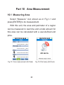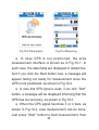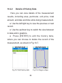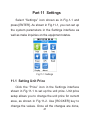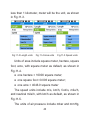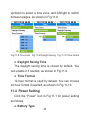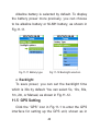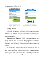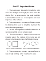
1
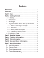
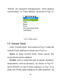
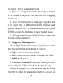
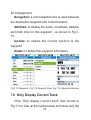
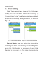
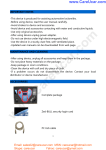
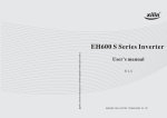
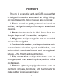
Foreword This unit is a versatile hand-held GPS receiver that is designed for outdoor sports such as riding, hiking, and mountaineering. Its key features are as follows: 1. Track: record the path you travel and used for auxiliary navigation and profile map of speed and elevation. 2. Route: input routes in the KML format from the Google Maps on a PC for auxiliary navigation. 3. Waypoint: multiple waypoints can be recorded and used for navigation. 4. Position Information: provide precise data such as coordinates, elevation, speed, and direction, can be in multiple coordinate formats such as longitude/ latitude, UTM, MGRS and customization. 5. Trip Information: multiple data items such as average speed, max speed, trip time, and trip miles are displayed. 6. Sensor: optionally equipped sensors such as electronic compass, barometer, and thermometer to make outdoor sports safe and easy. 1 Contents Foreword......................................................................................1 Contents.......................................................................................2 Part 1 Keys.................................................................................4 Part 2 Getting Started..........................................................8 2.1 Startup..............................................................................8 2.2 Shutdown.........................................................................8 2.3 Backlight...........................................................................9 2.4 System Status Bar at the Top of Screen............9 2.4.1 Table on GPS Signal Strength...............................10 2.4.2 Date/Time...................................................................10 2.4.3 Battery Status Description ......................................11 2.4.4 Indication of Battery Power .....................................11 2.5 Switching Page .........................................................12 Part 3 Satellite Status........................................................13 Part 4 Position Information............................................15 Part 5 Trip Information......................................................17 Part 6 Sun and Moon Information...............................18 Part 7 Map Information.....................................................19 7.1 Map Information ..........................................................19 7.2 Current Track ...............................................................21 7.3 Track Management.....................................................23 7.4 Route Management....................................................24 2 7.5 Waypoint Management.............................................26 7.6 Only Display Current Track......................................27 7.7 Track Setting.................................................................28 Part 8 GOTO............................................................................30 Part 9 Stopwatch..................................................................34 Part 10 Area Measurement............................................35 10.1 Measuring Area..........................................................35 10.2 History Data.................................................................38 10.2.1 List of Data............................................................38 10.2.2 Details of History Data......................................39 Part 11 Settings.....................................................................41 11.1 Setting Unit Price.......................................................41 11.2 Setting Measurement Unit.....................................42 11.3 Setting Time.................................................................44 11.4 Power Setting.............................................................45 11.5 GPS Setting................................................................46 11.6 Memory Clearance...................................................51 11.7 Display Setting...........................................................52 11.8 About This Unit...........................................................53 Part 12 Connect to PC&Output Data.........................54 12.1 Connect to PC............................................................54 12.2 Data Output................................................................55 Part 13 Important Notes...................................................56 Appendix Specifications for This GPS.....................57 3 Part 1 Keys Fig.1-1 Keys 4 [ON/OFF]: turn on/off the equipment. [BACKLIGHT]: light/dim the backlight. [ESC]: exit from current interface and back to the previous one. [ROCKER]: ENTER key, also up/down/left/right key. [MARK]: update the current location to MOB point. [GOTO]: switch to the waypoint navigation interface. [MENU]: pop up a menu related to this interface. [NAV]: jump to the main menu interface and then can switch between the satellite status, position information, and trip information interfaces. [ZOOM OUT]/[ZOOM IN]: zoom out or zoom in map scale. 5 Fig.1-2 Area Fig.1-3 GOTO Fig.1-5 Satellite Fig.1-6 Position 6 Fig.1-4 Sun/Moon Fig.1-7 Trips Fig.1-8 Stopwatch Fig.1-9 Map 7 Fig.1-10 Settings Part 2 Getting Started 2.1 Startup 1. Press [ON/OFF] button for at least 2 seconds to turn on the equipment. 2. To avoid turning on the equipment inadvertently, a welcome interface can be seen while turning on the device, and press [ENTER] to continue. Otherwise, the equipment will be shut down automatically in 10 seconds. Fig.2-1 Startup interface 2.2 Shutdown Press [ON/OFF] button for 2 seconds to shut down 8 the unit. 2.3 Backlight Three levels of backlight are available: strong, medium,and weak. The default level is weak backlight. The [BACKLIGHT] button can be used to adjust the brightness circularly. The higher the brightness level, the more power needed. 2.4 System Status Bar at the Top of Screen The system status bar is at the top of the screen. It displays strength of the GPS signal, date, time, measurement status, and battery level. 9 2.4.1 Table on GPS Signal Strength Signal Strength Description 5 bars, when positioning is best made most accurately 4 bars 3 bars 2 bars, where 3D positioning is made 1 bar, where 2D positioning is made not positioned yet GPS closed WAAS ON 2.4.2 Date/Time It displays the current date in year/month/day format and time in hour/minute format. 10 2.4.3 Battery Status Description Status Power levels Less than 10% of full battery power 10% of full battery power 30% of full battery power 50% of full battery power 70% of full battery power 100% of full battery power 2.4.4 Indication of Battery Power The current level of battery power is indicated in the status bar at the top of the screen. ● In case the power is less than 20% or 10%, a window will pop up indicating the low level. The user can press [ESC] to exit the window, as shown in Fig.2-2 and Fig.2-3. ● In case the power level is too low, the equipment 11 will be shut down automatically, as shown in Fig.2-4. Fig.2-2 < 20% Fig.2-3 < 10% Fig.2-4 Shut down 2.5 Switching Page When the icons are available on the screen, you can use the left/right key to go to the previous or next pages. When the icon are available on the screen, you can use the up/down key to go to the previous or next pages. 12 Part 3 Satellite Status Select “Satellite” icon shown as in Fig.1-1 and press [ENTER]. You can check reception of the satellite signals in the Satellite interface, shown as in Fig.3-1. Fig.3-1 Satellite status ● The digits and bars indicate the satellite number and its signal strength, with green bar indicating the satellite already being engaged for positioning and red bar indicating the ones not being engaged. ● The above sky graphics indicates positions of 13 the satellites found in the sky. ● HDOP indicates accuracy of positioning, where the smaller the HDOP value, the smaller the error, and the higher the accuracy. 14 Part 4 Position Information Select “Position” icon shown as in Fig.1-1 and press [ENTER]. In the Position interface, you can find such data as coordinates, elevation, heading, speed, and position accuracy to indicate where you are, as shown in Fig.4-1. Fig.4-1 Position information ● You can change the coordinate format and speed unit in the Settings interface. ● “Accuracy” means current accuracy of the GPS positioning. ● “Heading” means where you are heading for, 15 with 0 degree for north, 90 degrees for east, 180 degrees for south, and 270 degrees for west. This parameter will be unavailable while the equipment is stationary. 16 Part 5 Trip Information Select “Trips” icon shown as in Fig.1-1 and press [ENTER]. The Trips interface provides such information as current speed, max speed, overall average speed, moving average speed, moving time, total time, trip and odometer, as shown in Fig.5-1. Fig.5-1 Trip information Fig.5-2 Trips menu ● Here can press [ENTER] to enter the Travel menu interface as shown in Fig.5-2, in which you can clean up the trip and odometer information. 17 Part 6 Sun and Moon Information Select “Sun/Moon” icon shown as in Fig.1-1 and press [ENTER]. The sun/moon interface provides such information as sunrise/sunset time, moonrise/ moonset time, lunar phase, and weekdays of the current location, as shown in Fig.6-1. Fig.6-1 Sun and moon information In this interface, you can use the up/down key to change the month, and the left/right key to change the day. 18 Part 7 Map Information 7.1 Map Information Select “Map” icon shown as in Fig.1-1 and press [ENTER]. A question mark will appear on the Map interface if positioning is not done, with the coordinates at the last shutdown being displayed. Once positioning is done, the question mark is turned into a triangle arrow. The Map interface displays your moving tracks in real time and the waypoints recorded, as shown in Fig.7-1 and Fig.7-2. Fig.7-1 Map Fig.7-2 Roaming mode The triangle arrow indicates current moving 19 direction while real-time moving track in the blue lines. The tracks, routes, and waypoints recorded are displayed in a red line, and only one of them can be displayed at one time. Click the up/down/left/ right key and a black cross cursor will appear on the screen, indicating you enter the roaming mode, as shown in Fig.7-2. The cross cursor moves while you are pressing the up/down/left/right button. And on the screen there appear the latitude/longitude coordinates of the cursor position, distance to the current position, and the bearing. Click ESC to exit the roaming mode, and the cross cursor and related information will disappear. At the bottom left of the screen displays the map scale and you can click [ZOOM IN/OUT] button to change the scale. On the Map interface, click [MENU] button then to enter the Map Setting interface in which you can select what to do next: “Current track”, “Tracks” for track management, “Routes” for route management, 20 “Points” for waypoint management, “Only display Current track”, or “Track Setting”, as shown in Fig.7-3. Fig.7-3 Map setting 7.2 Current Track Click “Current track” item shown in Fig.7-3 and the Current Track interface is shown as in Fig.7-4. Save: to save current track. Once saved, the current track will be updated. Profile: click to select the plot of speed, elevation, temperature, and air pressure, as shown in Fig.7-5. Click ENTER on the Profile interface in Fig.7-5 to enter the Profile data interface for data selection, as 21 shown in Fig.7-6. Attribute: click to display the start time, length, area, number of points, duration (00:56 mean 0 hour and 56 minutes), average speed and max speed, as shown in Fig.7-7. Delete: to clear the current track. Fig.7-4 Current track menu Fig.7-5 Profile 22 Fig.7-6 Profile data Fig.7-7 Track attributes 7.3 Track Management Click “Tracks” item shown as in Fig.7-3 and the Track interface shows as in Fig.7-8. All the stored tracks can be listed in the Tracks interface, as shown in Fig.7-8. You can use the left/ right key to switch pages and the up/down key for track selection. Once a track file is selected, you can do operations on it by pressing [ENTER], as shown in Fig.7-9. In Fig.7-9, “Active” item is to show the track with a red line in the map display; “Profile” and “Attribute” 23 items mean same as in the Current Track interface. “Delete” item is for deleting the track. Fig.7-8 Tracks list Fig.7-9 Tracks Menu 7.4 Route Management Click “Routes” item shown as in Fig.7-3 and all the saved routes will be displayed in the Routes interface, as shown in Fig.7-10. Select a route and press [ENTER] to enter the route management interface, as shown in Fig.7-11. Select “Active” item and press [ENTER] to display the route in a red line and the current track continues to be displayed in a blue line. Select “Attribute” item and 24 press [ENTER] to display the route name, number of its segments, route length and route area, as shown in Fig.7-12. “Delete” item is for deleting the routes. Fig.7-10 Route list Fig.7-11 Route Menu Fig.7-12 Route attributes You can make a KML route from the Google Map and import it to the file folder “ROUTE” in the equipment through a data cable. The KML route can be made as follows: 1. Open the Google Map, select a start point from the map, right click the mouse button. Select “Directions from here” to set the start point. 2. Select a destination on the map, right click the mouse button, select “Directions to here” to set the 25 end point. Then a route is displayed. 3. You can change the route by pressing left button of the mouse in anywhere on the route and dragging the mouse. 4. Click on the top left of the page, copy the link or the short URL to address bar in the browser, and append “&output=kml” to the link address, then press ENTER, you will be prompted to save the kml route. 5. Simply save it in the ROUTE folder under root directory of the equipment. 7.5 Waypoint Management As in Fig.7-13, the following waypoints are listed after clicking “Points” item shown in Fig.7-3. ● ON: means location on startup ● OFF: means location when shutdown last time ● MOB: MOB point ● Points of interest(POIs) are displayed with names of Home, Office, Car, Boat, Port and Camp. Select a waypoint with the up/down key and click [ENTER] to enter the Waypoints interface in Fig.7-14 26 for management. Navigation: a red navigation line is used between the destination waypoint and current location. Attribute: to display the name, coordinate, altitude, and mark time for this waypoint , as shown in Fig.715. Update: to update the current position to the waypoint. Delete: to delete this waypoint information. Fig.7-13 Waypoints Fig.7-14 Waypoint Menu Fig.7-15 Waypoint attributes 7.6 Only Display Current Track Click “Only display Current track” item shown in Fig.7-3 to hide all the tracks/routes and show only the 27 current track. 7.7 Track Setting Click “Track setting” item shown in Fig.7-3 for track setting. You can select the interval for recording by “Record Mode” in the Track Setting interface and it will be saved automatically during shutdown, as shown in Fig.7-16. Fig.7-16 Recording interval Fig.7-17 Save during shutdown Record Mode: you can select the interval for recording the track. “Low Density” for recording once every 10s, “Mid Density” for once every 5s, and “High Density” for once every 2s. The higher the density, the 28 more the recording, and the more memory used. “Mid Density” is defaulted by the system. Auto Save: it allows you to select whether the current track is automatically saved while the equipment is being shut down, as shown in Fig.7-17. It is defaulted to Yes. 29 Part 8 GOTO GOTO function allows single point navigation where the waypoints recorded can be used for navigation. Press [GOTO] button or Select “GOTO” icon in Fig.1-1 to press [ENTER], then enter GOTO interface and the following waypoints are listed: “OFF” (name of waypoint at last shutdown), “ON”(name of waypoint at startup), and other POIs including “MOB”, “Home”, “Office”, “Car”, ‘’Boat”, ‘’Port”, ‘’Camp”, all with the date displayed, as shown in Fig.8-1. Fig.8-1 Waypoint navigation 30 ● OFF: means the location when last shutdown and cannot be updated manually. ● ON: means the location when startup and cannot be updated manually. ● MOB: press [MARK] button and you will be asked whether to update the MOB point, as shown in Fig.8-2, and click [ENTER] for updating the MOB point with current location. Then a message “Has been Updated “ appears, as shown in Fig.8-3. Fig.8-2 Update MOB point ● Fig.8-3 MOB Updated Other waypoints: you can maintain up to six POIs,named“Home”,“Office”, “Car”,”Boat”,”Port”,”Camp”. 31 Select a waypoint and press ENTER to start waypoint navigation, as shown in Fig.8-4. This interface displays the waypoint which you are heading for, including such information as distance to destination, speed, time to be used, estimated arrival time, and mark time. The arrow indicates the direction in which you are heading. And the red point on the outer circle is the direction in which the destination is located. When the arrow is pointing to the red point, it means you are heading for the destination. When you are coming very near to the destination, you will be prompted a message “Arrived !”, as shown in Fig.8-5. Fig.8-4 Navigation Fig.8-5 Arrived 32 Fig.8-6 POI menu Press [ENTER] on the waypoint navigation interface in Fig.8-4, to enter the POI menu interface where you can update or delete the POI, as shown in Fig.8-6. 33 Part 9 Stopwatch Select “StopWatch” icon shown as in Fig.1-1 and press [ENTER] to activate the stopwatch for second counting. The Stopwatch interface is shown as in Fig.9-1. ● Once you click the Start button, each time you click the Next button a record is saved. ● Up to 5 records can be saved. ● Click the Reset button to clear all the stopwatch records. Fig.9-1 Stopwatch 34 Part 10 Area Measurement 10.1 Measuring Area Select “Measure” icon shown as in Fig.1-1 and press [ENTER] to do measurement. With this unit, the area and perimeter of a region can be measured in real time and a total amount for this area can be calculated with a user-defined unit price. Fig.10-1 Area measurement (Not fixed) 35 Fig.10-2 Not ready (Not fixed) Fig.10-3 Weak signal Fig.10-4 Measuring ● In case GPS is not positioned, the area measurement interface is shown as in Fig.10-1. In such case, the data fields are displayed in dotted line. And if you click the Start button now, a message will appear telling not ready for measurement since the GPS is not positioned, as shown in Fig.10-2. ● In case that GPS signal is weak, if you click “Start” button, a message will be displayed informing that the GPS has low accuracy, as shown in Fig.10-3. ● When the GPS signal becomes 5 or 4 bars, as shown in Fig.10-4, area measurement can be done. Just press “Start” button to start measurement, then 36 “Start” button will become “Pause” button, and “Area” in the title bar will become “Measuring”, also with a flickering icon in the status bar. ● Delete: to clear the current measurement results. ● Save: to save the current measurement results. Note: to make the measurement result correct, please do not click the Delete or Save button while measurement is in progress. ● Up to 64 records for measurement can be saved. ● The unit of area can be changed in the Settings interface. ● Unit price can also be changed in the Settings interface, which will not affect the measurement results already saved. ● Switch to other interfaces does not affect measurement. 37 10.2 History Data 10.2.1 List of Data Click the History button in the area measurement interface, shown as in Fig.10-1 or Fig.10-4, to display the history data saved, as shown in Fig.10-5. Here you may use the up/down key to select data available and the left/right key to turn to other pages. To view details of the history data, just press [ENTER] on your selected data, then the details are shown as in Fig.10-6. Measurement data is saved in the MTRK folder under the root directory in TRL format. Fig.10-5 History data list Fig.10-6 Details of history data 38 10.2.2 Details of History Data Here you can view details of the measurement results, including area, perimeter, unit price, total amount, and date and time while doing measurement. ● Use the left/right key to view the previous or next record. ● Use the up/down key to switch the view between in data and in graphics. ● Press [ENTER] to edit the history data, where you can choose to delete the record of the measurement, as shown in Fig.10-7. Fig.10-7 Edit history data Fig.10-8 Region shape 39 On the shape of the region to be measured, the solid line indicates the path you have traveled, the dotted line is the link between the start and end points, where the start point is in green while the end point is in red. At the bottom is the map scale and the area of this closed region. Note: to minimize measurement error, it is required to walk along the closed region from the start point and back to the start point when doing measurement. 40 Part 11 Settings Select “Settings” icon shown as in Fig.1-1 and press [ENTER]. As shown in Fig.11-1, you can set up the system parameters in the Settings interface as well as make inquiries on the equipment status. Fig.11-1 Settings 11.1 Setting Unit Price Click the “Price” icon in the Settings interface shown in Fig.11-1 to set up the unit price. Unit price setup allows you to change the unit price for current area, as shown in Fig.11-2. Use [ROCKER] key to change the values. Once all the changes are done, 41 press [ENTER] to save. After the unit price is set, if the unit is changed, the unit price will be automatically calculated. Changing unit price will not affect the measurement results already saved. Fig.11-2 Price setting 11.2 Setting Measurement Unit Click the “Unit” icon shown in Fig.11-1 to set up units. You can set up units for length, area, speed, air pressure, and temperature. Units of length include meter, kilometer, foot, mile and nautical mile, with kilometer as default. In case of 42 less than 1 kilometer, meter will be the unit, as shown in Fig.11-3. ● one foot=0.3048m; ● one mile=1609 m; ● one nautical mile =1852 m; Fig.11-3 Length units Fig.11-4 Area units Fig.11-5 Speed units Units of area include square meter, hectare, square foot, acre, with square meter as default, as shown in Fig.11-4. ● one hectare = 10000 square meter; ● one square foot =0.093 square meter; ● one acre = 4046.9 square meter The speed units include m/s, km/h, foot/s, mile/h, and nautical mile/h, with km/h as default, as shown in Fig.11-5. The units of air pressure include mbar and mmHg, 43 as shown in Fig.11-6. ● one mbar=0.7501 mmHg. The units of temperature include Celsius and Fahrenheit, as shown in Fig.11-7. ● Celsius =(Fahrenheit-32)*(5/9). Fig.11-6 Units of air pressure Fig.11-7 Units of temperature 11.3 Setting Time Click the “Time” icon in Fig.11-1 for time setup. You can set up current time zone, daylight saving time, and time format. ● Time Zone You can change the time zone by [ROCKER] key, 44 up/down to select a time zone, and left/right to switch between pages, as shown in Fig.11-8. Fig.11-8 Time zone Fig.11-9 Daylight saving Fig.11-10 Time format ● Daylight Saving Time The daylight saving time is closed by default. You can enable it if needed, as shown in Fig.11-9. ● Time Format 12-hour format is used by default. You can choose 24-hour format if needed, as shown in Fig.11-10. 11.4 Power Setting Click the “Power” icon in Fig.11-1 for power setting as follows. ● Battery Type 45 Alkaline battery is selected by default. To display the battery power more precisely, you can choose to be alkaline battery or Ni-MH battery, as shown in Fig.11-11. Fig.11-11 Battery type Fig.11-12 Backlight selection ● Backlight To save power, you can set the backlight time which is 30s by default. You can select 5s, 10s, 30s, 1m, 2m, or Manual, as shown in Fig.11-12. 11.5 GPS Setting Click the “GPS” icon in Fig.11-1 to enter the GPS interface for setting up the GPS unit, shown as in 46 Fig.11-13. In this interface, you can select GPS cold start, enable/disable WAAS, whether to start static navigation, select coordinate systems and map datum, as shown in Fig.11-13. GPS setting may significantly affect the operation of the device. Thus to have it work properly, only professionals can be suggested to do this. Fig.11-13 GPS setting Fig.11-14 Coordinate systems Fig. 11-15 User grid ● GPS Cold Restart Where it will clear the satellite position calculated last time, the calendar and UTC time to restart. Then it will attempt positioning and locking up the satellites, and it will take a long time since no previous 47 information is available. In this case the gps receiver uses a method like polling to lock up signals available from all the satellites. ● Enable/Disable WAAS WAAS may make position and measurement more accurate in European and American, while it may lower accuracy of position and measurement in China. So it depends on your decision to enable/ disable WAAS. It is enabled by default. ● Static Navigation When to suppress GPS shifting, this function can be used, where position information can be updated only when the speed is over a threshold value. When static navigation is enabled and the equipment is moving in a speed less than the threshold value, the position information may not be updated, thus leading to work error of the equipment. This function is disabled as default. ● Coordinate System This function let you choose longitude/latitude (in 48 formats of degree, degree/minute or degree/minute/ second) to indicate the location, with degree/minute format as default. Alternatively, you can also choose to use UTM, MGRS or User grid to describe the location, as shown in Fig.11-14. UTM (Universal Transverse Mercator Grid System): it is a Cartesian coordinate system which is widely used in the topographic maps. MGRS(Military Grid Reference System): it is a gridbased reference system which is used in UTM and UPS grid(Universal Polar Stereographic) to represent the position with number and character. User Grid: it allows you to set up relevant parameters according to your needs, including the central meridian and central latitude (the central latitude and longitude values for local area), false east at origin (generally 500000 in China land), false north at origin (generally 0 in China land), projection scale (generally set to 1), and scale factor (generally set to 49 1), as shown in Fig.11-15. Fig.11-16 Map datum Fig.11-17 Customized datum ● Map Datum WGS84: As shown in Fig.11-16, the system uses WGS84 by default, but you can also customize your own map datum. Customized Datum: Each country has its own map datum, for example, Beijing54 Coordinate System and Xi’an80 Coordinate System used in China. To make the map datum more similar to that of the earth surface thus to minimize measurement error, you can customize the related parameters 50 based on your requirements, they are DeltaX, DeltaY, DeltaZ, DeltaA, and DeltaF, as shown in Fig.1117. For example, in Beijing54 system, DeltaA=“108”,DeltaF=“0.0000005”; while in Xi’an80 system, DeltaA=“-3”,DeltaF=“0”. Values of DeltaX, DeltaY and DeltaZ may vary depending on the areas. For values of these parameters, please inquiry your local surveying and mapping authority. 11.6 Memory Clearance Click the “Reset” icon in Fig.11-1 to enter the Reset interface for memory clearance, as shown in Fig.1118. ● Reset Factory Setting: to restore the factory setting. ● Delete Area Records: to clear all the results of area measurement. ● Clear Current Track: to clear the current track record. ● Clear All Track: to clear all the track records. ● Reset All: to clear all the user data and setting. 51 Fig.11-18 Reset Fig.11-19 Message Fig.11-20 Cleared Select an item from the list in Fig.11-18 for clearance, press [ENTER] to enter the interface shown in Fig.11-19, press [ENTER] again to complete the clearance, and then a message telling clearance completed is displayed, as shown in 11-20, press [ESC] for return. 11.7 Display Setting Click “Display” icon in Fig.11-1 to enter display setting, where you can select the display modes, as shown in Fig.11-21. 52 Fig.11-21 Display setting Fig.11-22 About the equipment ● Day Mode: display in black characters with white background. More clearly in daylight. ● Night Mode: display in white characters with black background. More clearly at night. ● Auto Mode: switch automatically between Day Mode and Night Mode based on the sunrise/sunset time. 11.8 About This Unit Click the icon “About” shown in Fig.11-1 to get information on this unit. You can get the version, serial number of this unit, measurement records, memory available, and so on, as shown in Fig.11-22. 53 Part 12 Connect to PC&Output Data 12.1 Connect to PC Once the GPS is connected to PC, it enters the USB Connection option interface, as shown in Fig.12-1. Select “Mass Storage” mode, and a USB drive will appear on the PC. At this time, all the jobs on the equipment, such as measurement and trip recording, will be stopped. While “Power Supply” mode is selected, operations on the equipment will not be affected. Fig.12-1 Mass Storage mode 54 12.2 Data Output This device allows data, such as area measurement results and real-time tracks, to be stored in memory. You can view, edit, save and delete the data on a PC. The USB data port is on the back of the device. ● Area measurement results are stored in the MTRK directory in the Google Navigator format (.trl file). You can use the GPSBabel software to convert the file into GPX format, which can be opened with the Google Earth software and displayed on the map. The Google Earth software can be downloaded at http://earth.google.com. 55 Part 13 Important Notes 1. The device uses high-quality transflective color LCD. The stronger the sunlight, the more clear the display. So it is recommended that weak backlight is selected for outdoor use to save power and have longer use of the batteries. 2. This device uses 2 AA batteries. Please remove the batteries if not used for long time, to prevent the device from being damaged. 3. Ni-MH rechargeable or alkaline batteries is recommended. No carbon batteries used. 4. This device can do area measurements on irregular region. But borders of the region are not allowed to be intersected, see the folllowing figures: Fig.13-1 Correct measurement Fig.13-2 Incorrect measurement 5. The measurement accuracy may be affected in case of high buildings or tall trees near the area. 56 Appendix Specifications for This GPS Index Descriptions SiRF Star III 7990 GPS chip with Receiver higher sensitivity and lower power Antenna consumption High quality ceramic antenna Acquisition time Hot <5s, Cold <45s Position accuracy <7m(95%), Performance Accuracy Features Display Dimensions (WXHXD) Weight Battery Storage Record performance Speed accuracy <0.1segment Transflective Color 2.2", 320*240 5.6cm*11.9cm*3.3cm 90g (without batteries) 2 AA batteries, weak backlight and Protective up to 20h for continuous use. IPX-7 Water-resistant Flash memory 128MB Track No limit, provided the memory allows. Route No limit, provided the memory allows. Waypoint Area 9 measurement Speed Limit Accuracy for WAAS <3m(95%), Elevation Operating range 64 records <1530KM/H <18600m 0℃~60℃ 57