1
ELOG
web box data logger
User Manual
0
1
04/10/2013
2
3
4
5
6
7
MS1-7533
EMBEDDED WEB PAGES ...............................21
CONTENTS
VII. QUICK PRESENTATION ................................21
VIII. CONNECTION TO AN ELOG ..........................22
Pre-requisites............................................................................. 22
Operating Mode ........................................................................ 22
IX.
LOG OUT FROM AN ELOG ............................22
Pre-requisites............................................................................. 22
I.
SAFETY .......................................................... 4
I.1
Preamble ........................................................................... 4
I.2
Initial precautions ............................................................. 5
Operating Mode ........................................................................ 22
X.
CONFIGURATION OF THE ETHERNET PORT ..23
Pre-requisites............................................................................. 23
II. WARRANTY, RESPONSIBILITY AND
INTELLECTUAL PROPERTY ...................................... 6
Operating Mode ........................................................................ 23
II.1
Warranty ........................................................................... 6
XI.
II.2
Intellectual property rights ............................................... 6
Pre-requisites............................................................................. 24
II.3
Copyright........................................................................... 6
Operating Mode ........................................................................ 24
II.4
Registered trademarks ...................................................... 6
II.5
Equipment end-of-life ....................................................... 6
DATE AND TIME CONFIGURATION ..............24
XII. IMPORT A CONFIGURATION INTO ELOG ......25
Pre-requisites............................................................................. 25
Operating Mode ........................................................................ 25
PHYSICAL DESCRIPTION ................................. 7
III.
OVERVIEW .................................................... 7
III.1
Packaging .......................................................................... 7
III.2
Optional accessories ......................................................... 7
III.3
Overview ........................................................................... 8
III.4
Fastening ......................................................................... 10
IV.
CONNECTION .............................................. 11
XIII. EXPORT A CONFIGURATION FROM THE ELOG
27
Pre-requisites............................................................................. 27
Operating Mode ........................................................................ 27
XIV. CONFIGURATION OF PORTS RS485 A AND
RS485 B ...............................................................28
Pre-requisites............................................................................. 28
Operating Mode ........................................................................ 28
Prior remarks ............................................................................. 11
IV.1
Front panel ...................................................................... 11
IV.2
Power supply for the ELOG ............................................. 12
IV.3
Status indicators ............................................................. 12
IV.4
The Ethernet port (Port C)............................................... 13
IV.5
The RS485 ports (Ports A and B) ..................................... 14
IV.6
Digital inputs ................................................................... 17
XVI. CREATION OF A MODBUS DRIVER ...............30
IV.7
Digital output .................................................................. 18
Pre-requisites............................................................................. 30
IV.8
Optical interface port ...................................................... 18
Operating Mode to Create a Driver ........................................... 30
XV. CONFIGURATION OF DIGITAL INPUTS..........29
Pre-requisites............................................................................. 29
Operating Mode ........................................................................ 29
Operating Mode to Create a Simple variable ............................. 32
Operating Mode to create a Composite variable ....................... 34
V.
DATA LOGGING MODE ................................ 19
V.1
ELOG memory operating mode....................................... 19
XVII. ADD A DEVICE / ACTIVATE LOGGING ...........35
Pre-requisites............................................................................. 35
Operating Mode ........................................................................ 35
VI. TECHNICAL AND FUNCTIONAL LIMITS OF THE
ELOG ................................................................... 20
2
ELOG MS1-7533-00 User manual
XVIII. VISUALIZE THE MEASUREMENTS OF A DEVICE
IN REAL-TIME ...................................................... 38
XXII. ELOG REBOOT .............................................44
Pre-requisites ............................................................................. 38
Operating Mode ........................................................................ 44
Pre-requisites............................................................................. 44
Operating Mode ........................................................................ 38
XXIII. SYSTEM DATA INFORMATION .....................45
XIX. DELETE LOGS ............................................... 41
Pre-requisites............................................................................. 45
Pre-requisites ............................................................................. 41
Operating Mode ........................................................................ 45
Operating Mode ........................................................................ 41
XXIV.LEGAL MENTIONS........................................46
XX. DELETING DEVICES ...................................... 43
Pre-requisites ............................................................................. 43
XXV. CHARACTERISTICS .......................................51
Operating Mode ........................................................................ 43
XXVI.GLOSSARY ...................................................54
XXI. ELOG FIRMWARE UPDATE .......................... 44
Pre-requisites ............................................................................. 44
XXVII.INDEX .........................................................56
Operating Mode ........................................................................ 44
3
ELOG MS1-7533-00 User manual
I.
I.1
SAFETY
Preamble
You have just purchased an ELOG. Thank you for your choice.
To get the best from your device:
Read the following operating instructions before installing and using the device.
Follow the precautions for use stated in this document.
Meaning of symbol: Warning! Read the reference manual before using the device. In this
reference manual, failure to comply with or carry out instructions preceded by this
symbol can cause bodily harm or damage the equipment and installations.
Meaning of symbol: Information.
The specific definition of the word preceding the symbol is provided in the glossary at
the end of the document.
Make sure the device is intact and undamaged upon receipt. In the event of any problems,
please contact the after-sales department for any repairs or replacements.
The device described in this manual is intended to be used by trained staff only.
Any maintenance operations must be carried out by qualified and authorized personnel only.
For correct and safe use and for all maintenance operations, it is essential that staff follow
standard safety procedures.
This device is intended to be used in Category III installation and pollution degree 2 conditions in
accordance with standard IEC 61010-1.
Before installation, check that the supply voltage matches that of the mains supply network.
ELOG MS1-7533-00 User manual
4
I.2
Initial precautions
I.2.1
Safety precautions
Before any intervention, check that the device is unplugged from all power sources.
I.2.2
Precautions against electrical noise
Although the ELOG is protected from electrical and electromagnetically induced interference,
keep away from the immediate vicinity of equipment generating significant electrical noise (highpower switches, busbars, etc.). The quality of data communication on the data bus depends
heavily on taking such precautions.
I.2.3
Precautions in the event of downgraded operation
When safe operation is no longer possible, the instrument must be switched off and isolated.
This applies when:
- The device is visibly damaged during operation (whether the device still operates or not),
- The device does not work after prolonged storage in poor conditions,
- The device no longer works following severe damage during transport.
I.2.4
Cleaning instructions
When the monitor is disconnected from the mains, clean the outer surface using only a dry
cloth. Do not use abrasives or solvents. Prevent the connector terminals getting wet.
5
ELOG MS1-7533-00 User manual
II.
II.1
WARRANTY, RESPONSIBILITY AND INTELLECTUAL PROPERTY
Warranty
Unless expressly stipulated, the warranty runs for twelve months after the date of supply of the
monitor (extract from our General Conditions of Sale, available on request).
II.2
Intellectual property rights
All manuals and documentation of any nature are the property of ENERDIS and protected by
intellectual property rights, all rights reserved. They may not be distributed, reproduced, or
translated, in whole or in part, in any manner and in any form whatsoever.
II.3
Copyright
All rights reserved The reproduction, adaptation or translation of this manual with prior written
permission is prohibited, within the limits set out by the laws governing copyright.
Copyright ENERDIS – 2013.
First edition, June 2013.
II.4
Registered trademarks
ELOG is a trademark registered by ENERDIS.
II.5
Equipment end-of-life
The products which we sell do not fall within the scope of Decree No. 2005-829 relating to the
construction of electrical and electronic equipment and the disposal of waste arising from this
equipment.
In accordance with Article L541-2 of the Environmental Code, it is the responsibility of the holder of
the waste to dispose of it, or to make sure it is disposed of, appropriately.
6
ELOG MS1-7533-00 User manual
PHYSICAL DESCRIPTION
III.
OVERVIEW
III.1 Packaging
The equipment is delivered in compliance with your order. Each delivered product should contain, at
least, the following parts:
Name
Quantity
ELOG Product
1
Quick installation guide
1
III.2 Optional accessories
Name
Comment
Plate mounting kit
Allows fitting to the backplane of the cabinet
7
Code
ACCT1007
ELOG MS1-7533-00 User manual
III.3 Overview
ELOG is a centralization, collection, automatic logging and supervision unit for data from multifunction and multi-brand communications equipment (energy meters, power monitors, converters,
sensors, probes, PLCs, etc.).
ELOG is equipped with a number of communications tools for data acquisition and use.
5 Digital Digitals in pulse mode:
o for the reading of pulse output meter indices (water, gas, electricity, etc.).
1 Ethernet communications port for several uses:
o Modbus in master mode: real-time reading and periodic logging of the values of
variables from multi-function and multi-brand equipment communicating via
Modbus/TCP , and Modbus over TCP/IP protocols.
o web server: configuration of the ELOG product and real-time consultation of the
values of the variables of Modbus/TCP equipment, from embedded web pages;
o Ethernet network: integration in an overall Ethernet network for multi-product and
remote use of ELOG via HTTP protocol, using web services (supervision with E.
Online, Remote logging and display by spreadsheet, etc.)
2 RS485 master digital communication ports:
o Modbus RTU master mode : real-time reading and periodic recording of the values of
variables from multi-function and multi-brand equipment communicating via
Modbus RTU protocol.
1 optical communications interface:
o connectivity reserved for manufacturer maintenance.
ELOG is aimed both at the companies managing the monitoring and reduction of energy costs in an
environmental and sustainable development context, and at industrial groups with complex multienergy networks requiring precise management and monitoring.
All the information and data read and saved by ELOG can be used in several ways:
Embedded web pages: for the configuration and initialization of ELOG and viewing the
variables measured by Modbus and Modbus/TCP equipment.
Eonline2 software: monitoring, analysis and surveillance software for energy performance
which remotely carries out the periodic and automatic logging of the data saved and
archived in the ELOG via the Ethernet network (Eonline2 is a software program published
and distributed by ENERDIS).
8
ELOG MS1-7533-00 User manual
Excel Spreadsheet: provision of an Excel macro for the transfer and formatting of data in the
form of tables and graphs. An input window enables the selection of equipment, variables
and the period to analyze.
Third-party application: the web services in JSON format available in ELOG enable the
integration and use of information and data recorded on a number of applications (web
browser, android, ios, etc.), in a wide variety of programming languages (Java, JavaScript, C,
C++, Python, Labview, etc.).
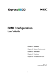
ELOG is an energy monitoring architecture:
9
ELOG MS1-7533-00 User manual
III.4 Fastening
ELOG is mounted on a DIN 35 mm rail, either in standard form or with screws thanks to the optional
plate mounting kit (ACCT1007). The normal operating position of ELOG is the horizontal position.
Assembly on DIN rail
Drilling diagram for fastening with screws
ELOG dimensions: 120.5x120x81 mm (D x W x H)
10
ELOG MS1-7533-00 User manual
IV.
CONNECTION
This paragraph presents ELOG connections and terminal boards, specifies their connection and use
and describes their electrical characteristics.
Prior remarks
Maximum applicable values
It should be noted that exceeding the maximum applicable values can lead to
a definitive deterioration of the device.
Cables and terminal boards
Connections are made on fixed-screw terminal boards for cables of a maximum section
of 6mm² (multistrand) or 4 mm² (single-strand) for all circuits.
IV.1 Front panel
The front panel of the ELOG is as follows:
No.
11
Function
See §
1.
Auxiliary power supply
IV.2
2.
Status indicators
IV.3
3.
Ethernet Port (C)
IV.4
4.
RS485 Ports (A & B)
IV.5
5.
Digital inputs
IV.6
6.
Digital output
IV.7
7.
Optical interface port
IV.8
ELOG MS1-7533-00 User manual
IV.2 Power supply for the ELOG
IV.2.1 Connection
The power supply circuit must be protected by fuses or a thermal magnetic
circuit breaker.
ELOG's power supply is connected to the ports marked as Aux.
IV.2.2 Characteristics
Source
Characteristics
Alternating
80 Vac to 265 Vac.
Frequency in the range of 42.5 Hz and 69 Hz on AC.
Direct
80 Vdc to 375 Vdc.
Polarity-insensitive
< 10 VA – 5 W.
Consumption
Non-removable terminals
2 connection points. Screw terminals, with mobile cage.
Connection of rigid or flexible wires of 4 to 6 mm2.
Maximum permitted torque on the terminal: 0.4 Nm.
Following a power cut, data is stored within the limits set out below.
Item
Characteristics
Information retention
10 years at 25°C (drivers an d settings)
Date / time retention
30 days.
Power reserve
2.5 sec (under 230 Vac).
IV.3 Status indicators
Three status indicators (LEDs) provide information on the functioning of the ELOG.
ON
Error
Unlit
Product off
Fixed green light
Product on
Unlit
No communication
Flashing green light
Communication on RS485 or optical
ports in progress
Unlit
No error
Flashing red light
Product error
12
ELOG MS1-7533-00 User manual
IV.4 The Ethernet port (Port C)
IV.4.1 Preamble
The Ethernet 10/100 Base T connector enables the ELOG to be connected to the Ethernet network,
for several uses:
o Modbus in master mode: real-time reading and periodic logging of the values of
variables from multi-function and multi-brand equipment communicating via
Modbus/TCP and Modbus over TCP/IP protocols.
o web server: configuration of the ELOG product and real-time consultation of the
values of the variables of Modbus/TCP equipment, from embedded web pages.
o Ethernet network: integration in an overall Ethernet network for multi-product and
remote use of ELOG via HTTP protocol, using web services (supervision with E.
Online, Remote logging and display in spreadsheet, etc.)
IV.4.2 Connection
ELOG communicates with equipment according to two operating modes:
Remote equipment is directly connected to the Remote equipment is indirectly connected to
Ethernet network
Connection through a the Ethernet network
Connection using an
switch or a hub.
RS485 Modbus / Ethernet gateway.
Ethernet connector LEDs
LED 1
Colour
LED 2
Meaning
Colour
Meaning
No connection.
Unlit
No activity.
Amber
Connection at 10 Mb per second.
Amber
Half duplex.
Green
Connection at 100 Mb per second.
Green
Full duplex.
Unlit
13
ELOG MS1-7533-00 User manual
IV.4.3 Ethernet port characteristics :
Item
Characteristics
Protocol
Modbus/TCP
and Modbus over TCP/IP
master mode
HTTP in slave mode
Data logging frequency from
network equipment
Analog type variable : every 5, 6, 10, 12, 15, 20, 30, 60, 120,
180, 240, 300, 360, 600, 720, 900, 1200, 1800 or 3600 seconds
Index type variable : every 1, 2, 3, 4, 5, 6, 10, 12, 15, 20, 30 or
60 minutes
Speed
10/100 Base T
Default address
192.168.0.2
Default mask
255.255.0.0
Maximum length
Transmission up to 100 m max.
Connection
8-pin RJ45 plug.
RTU mode in
IV.5 The RS485 ports (Ports A and B)
IV.5.1 Preamble
ELOG is equipped with two RS485 (RS485 A and RS485 B) digital inputs using Modbus/Jbus protocol
which operate in master mode. This enables ELOG to communicate with multi-function and multibrand equipment connected to Modbus networks. ELOG displays the values of variables from
equipment in real-time on its embedded web pages, and can periodically save them to memory.
IV.5.2 Layout
The RS485 communications ports are marked as
COM A and COM B on the front panel.
The ELOG runs in master mode for these two ports,
RS485 A and B.
14
ELOG MS1-7533-00 User manual
IV.5.3 Connection principle
Only tests on the real network can confirm the best combination (speed, network length, impedance
matching, etc.).
IV.5.4 Technical reminders and precautions for the 2-wire RS485 network
Type of cable to use:
Screened twisted-pair cable with a section of more than 0.2 mm2 (UL2493 or UL2919 type with
multiple screening for very noisy areas). The continuity of screening along the communications
network must be ensued, and the screening must be connected to the 0 V of the RS485 output on a
single piece of equipment of the RS485 MODBUS/JBUS network, generally at the start or end of line.
Installation of the RS485 cable:
The multi-pair cable must not be severed. Make a cut in the protective sheath and remove a pair (the
continuity of screening along the communications network is therefore ensured). If the cable has to
be cut, re-establish the continuity of screening by connecting the screening of the two ends of both
cables.
RS485 network structure:
If the routing of the RS485 network forces the network to be split into two or more distinct branches,
the route node must be equipped with an RS485 line amplifier or an nxRS485 line repeater HUB.
The maximum characteristics of an RS485 network are:
o maximum length: 1.2 km,
o Maximum 31 pieces of equipment connected to an RS485 segment.
The RS485 network can be extended to more than 1.2 km and 31 pieces of equipment through the
use of Modbus RS485 hubs / amplifiers.
Layout example:
15
ELOG MS1-7533-00 User manual
IV.5.5 Connection in a clean environment
For a RS485 network in a clean electrical environment, use a twisted-pair cable. This cable should
be connected to terminals A(+) and B(-). The convention adopted for terminals A and B
corresponds to EIA 485, specifying logic level "1" on the line corresponds to VB> VA and a logic
level "0" corresponds to VA> VB.
IV.5.6 Connection in a noisy environment
With screening:
In the case of particularly noisy electrical environment, a screened twisted pair should be used,
and the screening should be connected to the 0 V terminal of the ELOG.
With screening and resistors (polarization and load)
To improve the quality of transmission in noisy environments, it is possible to polarize the line at a
single point. This polarization sets the resting level, in the absence of transmission, by two 1.2 kΩ
resistors between the 0 V and 5 V lines. It is sometimes necessary to connect the two ends of the
bus via a 120 k Ω resistor.
16
ELOG MS1-7533-00 User manual
IV.5.7 RS485 port characteristics
Item
Characteristics
Protocol
Modbus RTU
Operating mode
Half duplex Master mode
Data logging frequency from
network equipment
Analog type variable : every 5, 6, 10, 12, 15, 20, 30, 60, 120,
180, 240, 300, 360, 600, 720, 900, 1200, 1800 or 3600 seconds
Index type variable : every 1, 2, 3, 4, 5, 6, 10, 12, 15, 20, 30 or
60 minutes
Speed
24,00, 4,800, 9,600, 19,200 and 115,200 Bauds.
Parity
no, even or odd.
Number of stop bits
1 or 2
Connection
Screened 2-wire, half duplex
Non-removable terminals
.
3 connection points. Screw terminals.
Connection of rigid or flexible wires between 4 and 6 mm2.
Maximum permitted torque on the terminal: 0.4 Nm.
Communication is in half duplex mode.. The functions implemented are:
- Function 03 : Read N words
- Function 04 : Read N words
- Function 16 : Write N words (not available)
IV.6 Digital inputs
IV.6.1 Preamble
ELOG has five independent digital inputs. They are marked ETOR1 to ETOR5. They work in pulse
mode : to each of them the user can connect any type of equipment working on this principle (water,
gas or electricity meter, sensor, etc.), complying with the following characteristics:
The received pulses are multiplied by the weightings of the pulses on this input and are then
summed in an Index type variable . The pulse weighting can be configured with a relation of
1/10000th, and each periodic reading of the index can be archived in the ELOG. The index start value
can be set to that displayed on the connected meter.
17
ELOG MS1-7533-00 User manual
IV.6.2 Digital input connection.
The electrical connection of digital inputs to ELOG requires the presence of an external Vdc power
source.
Connect the input signal as follows:
Example of the connection of
digital inputs in pulse mode.
The terminals are polarityinsensitive.
IV.6.3 Electrical characteristics of digital inputs:
Item
Characteristics
Number of inputs
5.
Operating mode
Counting
Input signal
Direct.
Logic levels
Level "0": Amplitude < 5 Vdc
Level "1": Amplitude > 7 Vdc and < 72 Vdc
Minimum duration of pulse at level "0": 30 ms
Minimum duration of pulse at level "1": 30 ms
Frequency of pulses
0 to 16.67 Hz
Power absorbed
< 0.5 W per digital input.
Isolation between inputs
2.2 kV – 1 min.
Type of protection
Optocoupler.
Logging frequency of the
index values of digital inputs
Every 1, 2, 3, 4, 5, 6, 10, 12, 15, 20, 30 or 60 minutes
IV.7 Digital output
Not available on this model.
IV.8 Optical interface port
This optical interface is exclusively reserved for manufacturer maintenance.
18
ELOG MS1-7533-00 User manual
V.
DATA LOGGING MODE
ELOG can periodically record the values of variables from equipment connected to:
Digital Digitals
: logging of Index type variables
RS485 A and RS485 B in Modbus RTU
: logging of Index and Analog type variables
The Ethernet connector in Modbus/TCP
Analog type variables.
and Modbus over TCP/IP
.
: logging of Index and
Value logging frequency can be adjusted for each type of variable, from the following values:
analog type variable: every 5, 6, 10, 12, 15, 20, 30, 60, 120, 180, 240, 300, 360, 600, 720, 900,
1200, 1800 or 3600 seconds.
index type variable : every 1, 2, 3, 4, 5, 6, 10, 12, 15, 20, 30 or 60 minutes.
V.1
ELOG memory operating mode
The memory depth is of:
3 months (month in progress, month-1, month-2) of data for logging frequencies of over 1
minute.
3 days (day in progress, day-1, day-2) of data for logging frequencies of less than 1 minute,
Warning: memory depth available to download is counted from the product's current date and time.
Data below 1 minute will no longer be available for download if an ELOG is left unplugged for more
than 3 days. Data over 1 minute will no longer be available for download if an ELOG is left unplugged
for more than 3 months.
19
ELOG MS1-7533-00 User manual
VI.
TECHNICAL AND FUNCTIONAL LIMITS OF THE ELOG
Driver:
Max number of drivers: 100,
Max number of configurable Simple variables
per driver: 30,
Max number of configurable Composite variables
Device:
per driver: 10.
\h
Max number of configurable devices: 100.
Type of variables recorded :
Index type variable
Analog type variable
Logging frequency :
Analog type variable: every 5, 6, 10, 12, 15, 20, 30, 60, 120, 180, 240, 300, 360, 600, 720, 900,
1,200, 1,800 or 3,600 seconds:
Index type variable : every 1, 2, 3, 4, 5, 6, 10, 12, 15, 20, 30 or 60 minutes
Adjustable independent frequency for each device.
Logging capacity:
Max number of periodically logged variables: 50,
3 months (month in progress, month-1, month-2) of data for logging frequencies of over 1
minute,
3 days (day in progress, day-1, day-2) of data for logging frequencies of less than 1 minute,
Memory operating mode: FIFO
(First In First Out).
8 GB storage capacity.
20
ELOG MS1-7533-00 User manual
EMBEDDED WEB PAGES
VII.
QUICK PRESENTATION
The general web interface of ELOG looks as follows:
It is made up of three main areas:
-
A scrolling menu bar enables you to browse through ELOG's various embedded web
pages.
A list of all the Devices
configured on the ELOG.
An actions area, containing all the actions which can be performed on the device in
question.
Browsing within an ELOG can be done through the upper menu of the page. You can only access all
the features of your ELOG through its web pages.
The flag icon enables the menu display language to be selected: French / English.
Notes
-
<@IP_ELOG> is used to specify the IP address of the configured ELOG.
http:// <@IP_ELOG> is used to specify the URL of embedded pages of the ELOG.
21
ELOG MS1-7533-00 User manual
VIII.
CONNECTION TO AN ELOG
This paragraph explains how to connect to an ELOG from an internet browser
Pre-requisites
You have an internet browser and access to a network the ELOG is connected to.
Operating Mode
The default IP address of your ELOG is 192.168.0.2 (mask: 255.255.0.0).
For connection to the default IP address of your ELOG :
Configure the network card of your computer to connect to the same subnet as ELOG (for
example, configure IP address 192.168.0.3 / 255.255.0.0).
Open your internet browser and enter the following HTTP address in the URL bar:
http://192.168.0.2
Enter Login: "enerdis".
Enter the password: "!elog2013!".
Click on the
IX.
icon to validate.
LOG OUT FROM AN ELOG
This paragraph explains how to log out from an ELOG from an internet browser
Pre-requisites
You are connected to one of the pages of an ELOG (apart from the authentication page).
Operating Mode
Click on the "Log out" to return to the authentication page.
Close your internet browser.
22
ELOG MS1-7533-00 User manual
X.
CONFIGURATION OF THE ETHERNET PORT
This paragraph explains ELOG Ethernet network configuration (port C)
Pre-requisites
Your computer is connected to your ELOG with a crossover cable and you have logged in.
Operating Mode
Click on "System > Ethernet Port".
You have to fill in:
o The host name of your ELOG on the network.
o The length of the Timeout : (by default 500 ms).
o The type of assignment of the IP address of your ELOG.
Select "Static" if you want to configure the IP address and network mask of
your ELOG. Beware, if you change your network, ELOG will no longer be
visible from your computer and you will need to reconfigure your own
network settings. (Recommended).
Select "DHCP" (Dynamic Host Configuration Protocol) if your ELOG is
connected to a network with a DHCP server. An address IP is then
automatically assigned to your ELOG by the DHCP server of the network.
o The new IP address,
o The value of the subnet mask.
Fill in the optional fields:
o SMTP (mail server), NTP (synchronization of date and time), Gateway and DNS.
Click on "Modify" for the new settings to be taken into account. The message "Ethernet port
modified successfully" confirms that the operation has been successfully completed. Click
"Cancel" to exit the section without making any changes.
23
ELOG MS1-7533-00 User manual
XI.
DATE AND TIME CONFIGURATION
This paragraph explains how to configure the date and time on an ELOG
Pre-requisites
Your ELOG is accessible and you are connected to its embedded web pages.
Operating Mode
Go to "System > Date".
Select your time zone from the drop-down list.
Click on "Synchronize with the desktop" to transfer the new date/time to ELOG.
Click on "OK" for the ‘synchronization complete’ message to validate the synchronization of
the time and date between your desktop and the ELOG.
The ELOG's time and date can be synchronized to an NTP (Network Time Protocol) server
(see "Configuration of the Ethernet port" paragraph).
24
ELOG MS1-7533-00 User manual
XII.
IMPORT A CONFIGURATION INTO ELOG
This paragraph explains how to import a list of Devices and/or Drivers into ELOG from an existing
configuration file
Pre-requisites
Your ELOG is accessible and you are connected to its embedded web pages.
You know the location of the configuration file to import (xxxx.tar.gz type file).
Operating Mode
Go to "Configuration exchanges > Configuration import".
Two options are available:
Import the entire configuration :
o The entire list of Devices and associated Drivers
contained in the file xxxx.tar.gz are imported into
the ELOG.
o Note: The network configuration is not modified.
Driver import :
o If the driver is already in the list contained in the file
xxxx.tar.gz in the ELOG, it is updated.
Driver bookshop interns import :
o The whole list of Drivers contained in the bookshop
of ELOG is downloaded in the ELOG.
Important :
Every Test point (PdM), Driver or Variables contained in a Driver are identified by a unique
key. The import of a list of PdM and/or Drivers (via the commands" Import the entire
configuration " - " Driver Import" - " Driver bookshop interns import") entraine for all the
elements (PdM, Driver or Variable) with an identical key :
• The replacement of this element by that imported
• All the elements possessing a not pre-existent key in ELOG are added
The modification of an element (PdM, Driver or Variable) in ELOG entraine not no
modification of its key. Only the addition of an element (PdM, Driver or Variable) entraine the
creation of a new key
25
ELOG MS1-7533-00 User manual
Import the entire configuration :
Click on "Choose a file" and select the file to import (e.g.: config.tar.gz) in the tree structure
of your computer, then click on "Open".
Then click on "Import". The "Configuration updated" message confirms that the import has
been successfully completed.
Driver import :
Click on "Choose a file" and select the file to import (e.g.: config.tar.gz) in the tree structure
of your computer, then click on "Open".
Then click on "Import". The "Configuration updated" message confirms that the import has
been successfully completed.
Driver bookshop interns import :
Then click on "Import". The "Configuration updated" message confirms that the import has
been successfully completed.
Check the import by clicking on "Configuration > Devices" for a configuration import, or
"Configuration > Drivers" for a driver import.
26
ELOG MS1-7533-00 User manual
XIII.
EXPORT A CONFIGURATION FROM THE ELOG
This paragraph explains how to export a list of Devices and/or Drivers from the ELOG
Pre-requisites
Your ELOG is accessible and you are connected to its embedded web pages.
Operating Mode
Click on "Configuration exchanges > Configuration export".
Two options are available:
Export the entire configuration:
o The entire list of Devices and associated Drivers
Driver export:
o Only the list of drivers is saved in a file.
are saved in a file.
Click on "Export".
Check "Save file", then validate with "OK".
The file (config.tar.gz) is then saved into the folder which you have defined in Windows to
store your downloads (by default: My Documents / Downloads).
You can then rename your file, maintaining the initial syntax.
E.g.: config ELOG1 192-168-0-11.tar.gz.
27
ELOG MS1-7533-00 User manual
XIV.
CONFIGURATION OF PORTS RS485 A AND RS485 B
This paragraph explains how to configure the ELOG's RS485 ports
Pre-requisites
Your ELOG is accessible and you are connected to its embedded web pages.
Operating Mode
Click on "Communications > Ports RS485 A and B".
Select the communication port to configure (Port A or Port B).
In the "RS485 communication settings", you must fill in the following fields:
o Speed (bauds - Default setting: 9600),
o Stop bits (bits - Default setting: 1),
o Parity (Default setting: No parity),
o Timeout : (ms – Default setting: 500),
o Delay between 2 requests : (ms – Default setting: 50).
Click on "Modify" to save the settings or "Cancel" to exit the section without making any
changes.
28
ELOG MS1-7533-00 User manual
XV.
CONFIGURATION OF DIGITAL INPUTS
This paragraph explains how to configure the ELOG's digital inputs (pulse mode)
Pre-requisites
Your ELOG is accessible and you are connected to its embedded web pages.
Operating Mode
Go to "Configuration > Digital Digitals
Click on the
Fill in:
o
o
o
o
o
o
".
icon in the digital input line (1 to 5) to configure.
A "Label" for your digital input.
The digital input mode ("Counting" mode as default).
The Index type variable measurement "unit" of the meter.
Either enable or disable the possibility of creating periodic Indexs of the number of
pulses generated by the meter of this digital input. Logs are validated upon creation
of a Device.
The "Pulse weight" of the pulse output of the meter which you want to assign to the
digital input (x 1/10000th - Default value: 10000).
E.g.: meter output pulse weight 2.5 kWh/pulse,
→ Value to fill in 2.5 x 10,000 = 25,000.
Possibly the initial value of the index, if your meter displayed a non-zero value before
connection to the ELOG's digital input.
E.g.: value displayed on the meter of 256982.52 kWh,
→ Value to fill in 256,982.52 x 10,000 = 2,569,825,200.
Click on "Validate" to save the digital input settings or "Cancel" to exit the section without
making any changes.
29
ELOG MS1-7533-00 User manual
XVI.
CREATION OF A MODBUS DRIVER
This paragraph explains the procedure to follow to create a Modbus Driver associated with a
type of device connected to the RS485 or Ethernet inputs.
A Driver comprises variable and/or variable Modbus variables .
Pre-requisites
Your ELOG is accessible and you are connected to its embedded web pages.
You know the brand and model of the device to be used.
You have a memory map and the table of measurements for the equipment to be used.
Operating Mode to Create a Driver
Go to "Configuration > Drivers".
On the left of the page the list of drivers already created is visible. If the driver which you
want to use is not on this list you must create it. The following procedure should be followed:
Fill in:
o A "Label" for your driver.
o A "Version" reference for the driver.
o Protocol: Modbus RTU (default value).
30
ELOG MS1-7533-00 User manual
Click on "Add" to create the driver.
The created driver is highlighted in blue in the table of drivers.
You can:
o "Delete" a driver by clicking on the
icon,
o "Modify" a driver by clicking on the
icon,
o "Copy" a driver by clicking on the
icon.
IMPORTANT: It is not possible to delete a driver if it is associated with a Device
31
.
ELOG MS1-7533-00 User manual
Operating Mode to Create a Simple variable
Locate your driver in the list of drivers.
Then click on the
icon to add variables to the driver.
Click on "New Simple variable"
.
Fill in:
o The variable's "Label".
o The "Unit" of the simple variable.
o The "Address" in the mapping to read the variable.
o The "Type" of variable:
Index type variable : if it is a variable to measure an accumulated value over
time (index of an energy meter, quantity of product units manufactured,
etc.).
Analog type variable : if it is a simple measurement variable (instant value,
average, etc.).
o The "Size" of the variable:
uint: full value without sign,
int: full value with sign,
float: actual value,
Followed by the number of bits of which this variable is made up (16, 32 or 64).
E.g.: uint 32: Full value without sign encoded on 32 bits.
o
o
The "Bytes arrangement" which corresponds to the read order of the bytes of the
variable:
2-1-4-3,
4-3-2-1 (big endian): High Byte at the lowest address,
1-2-3-4 (little endian): Low Byte at the lowest address,
3-4-1-2.
The "Mask" enables just part of the variable to be used (e.g.: the mask to use for the
8 first bits of a 32 bit big endian is 00000000-00000000-00000000-11111111 in
binary so 000000 FF in hexadecimal).
Example:
32
ELOG MS1-7533-00 User manual
o
o
o
o
o
o
The "Gain": multiplying factor to apply to the variable (Default value: 1).
The "Offset" to add to the value of the variable (Default value: 0).
"Variable visibility" : select "Yes" in the "Variable visibility" box if the variable needs
to be displayed on the web pages of the ELOG.
Either enable or disable the possibility of creating periodic Indexs of the value of
the variable. Logs are validated upon creation of a Device.
The "read function code": JBUS function enabling the reading of n words. (3 or 4,
Default value: 3).
The "write function code": JBUS function enabling the writing of n words. (16)
Click on "Add" to save the newly filled-in variable.
Then use the "New simple variable" command to add to the list of simple variables.
From the list of simple variables you can:
o "Delete" a simple variable by clicking on the
icon,
o "Modify" a simple variable by clicking on the ,
o "Copy" a simple variable by clicking on the ,
33
ELOG MS1-7533-00 User manual
Operating Mode to create a Composite variable
Click on "New Composite variable" (this section enables variables to be created from the
combination of simple variables defined in the "New simple variable" stage).
Fill in the "New Composite variable" section:
o The "Label" for the composite variable to create,
o The "Unit of the composite variable.
o The "Type" of variable:
Index type variable: if it is a variable to measure an accumulated value over
time (index of an energy meter, quantity of product units manufactured, etc.).
Analog type variable : if it is a simple measurement variable (instant value,
average, etc.).
o "Operand 1": select from the list of available simple variables.
o Select an "Operation" (+, -, x, /).
o "Operand 2": select from the list of available simple variables.
o Either enable or disable the possibility of creating periodic Indexs of the value of
the variable. Logs are validated upon creation of a Device.
Click on "Add" to save the newly filled-in variable.
Then use the "New composite variable" command to add to the list of composite variables.
From the list of composite variables you can:
o "Delete" a composite variable by clicking on the
icon,
o "Modify" a composite variable by clicking on the
icon,
o "Copy" a composite variable by clicking on the
icon.
34
ELOG MS1-7533-00 User manual
XVII.
ADD A DEVICE / ACTIVATE LOGGING
This paragraph explains the procedure to follow to create a Device which will be associated to a
driver or digital input.
Pre-requisites
You have already thought out the geographic or functional organization of the various Devices
your installation. (Level 1, 2, 3, 4 and category).
Your ELOG is accessible and you are connected to its embedded web pages.
The Driver for the device exists and/or the Digital input is configured.
for
Operating Mode
Click on "Configuration > Devices".
The following window is displayed:
Fill in:
o A "Label" for your Device
o The "Type": "Driver" or "Digital Input"
Driver:
-
Choose the "driver label" from the scroll-down list.
Either enable or disable "Index logs ". If you choose "Active", the
chronological logging of all values of the index type variable of the
device is activated.
35
ELOG MS1-7533-00 User manual
-
Define the "Index Logging frequency " (possible values are: 1, 2, 3,
4, 5, 6, 10, 12, 15, 20, 30, 60 minutes).
-
Either enable or disable "Analog measurement logs ". If you choose
"Active", the chronological logging of all values of the analog type
variable of the device is activated.
-
Define the "Logging frequency of analog measurements" (possible
values are: 5, 6, 10, 12, 15, 20, 30, 60, 120, 180, 240, 300, 360, 600,
720, 900, 1200, 1800 or 3600 seconds).
-
Choose the communications port which the "RS485 port A or RS485
port B or Ethernet Port" equipment is connected to.
o RS485 port A or RS485 port B : Fill in the protocol (Modbus
RTU as default) and the Modbus slave address
of the
Device equipment.
o Ethernet Port: choose Modbus/TCP or Modbus over
TCP/IP
Modbus/TCP: fill in the IP address of the Device
equipment, the port number (502 as default) and the
slave address of the Device equipment (1 as default).
Modbus over TCP/IP: fill in the IP address of the
gateway, the port number (502 as default) and the
Modbus address of the Device (1 as default).
Digital Input :
-
Select the "digital input number" (1 to 5) which the Device
equipment has been connected to.
-
Either enable or disable "Index logs ". If you choose "Active", the
chronological logging of all values of the index type variable of the
digital input is activated.
-
Define the "Index Logging frequency " (possible values are: 1, 2, 3,
4, 5, 6, 10, 12, 15, 20, 30, 60 minutes).
o
Fill in the Device "Level" and "Category" fields (Optional).
Click on "Add" to save the Device.
The created Device is highlighted in blue in the Device table.
36
ELOG MS1-7533-00 User manual
Refresh your browser display to show Device labels in alphabetical order.
From the list of Devices, you can:
o "Delete" a Device by clicking on the
icon,
o "Modify" a Device by clicking on the
icon,
o "Copy" a Device by clicking on the
icon.
37
ELOG MS1-7533-00 User manual
XVIII.
VISUALIZE THE MEASUREMENTS OF A DEVICE IN REAL-TIME
This paragraph explains how to view the measurements read in real-time by Device equipment.
Pre-requisites
Your ELOG is accessible and you are connected to its embedded web pages.
Equipment must be operational.
A Device
needs to have been created.
Operating Mode
Click on "Configuration > Devices".
The following window is displayed:
In area ,
o Check that the logging state is active
o Click on the "Restart logging" button if required.
o Click on the "refresh" icon
to update the "Number of measures with logging".
38
ELOG MS1-7533-00 User manual
The colour code used for the strip is:
Green: Logging is active.
Red: logging is off.
Green: The number of measures with active logging is
comprised between 1 and 44 inclusive
Amber: The number of measures with active logging is
comprised between 45 and 50 inclusive
Red: The number of measures with active logging is higher
than 50
In area ,
o Check the addresses of Devices:
ETOR (1 to 5)
A (@i)
B (@j)
C (IP :k @k)
o
The Device is connected to one of the five Digital Digitals .
The Device is connected to the Modbus network to port A and its
address is i.
The Device is connected to the Modbus network to port B and its
address is j.
The Device is connected to the Ethernet network to port C. The
following are displayed in the brackets, in this order: the IP
address of the Device, the relevant port number and the Modbus
address of the Device on the port.
Click on the "refresh" icon
to update the communication status.
Three situations can then arise:
Successful communication with the equipment.
Status not determined by ELOG.
Unsuccessful communication with the equipment.
39
ELOG MS1-7533-00 User manual
In area , click on the
icon.
This action enables a pop-up window to open, to see the measurements associated with the
driver (or the digital input) of the Device.
40
ELOG MS1-7533-00 User manual
XIX.
DELETE LOGS
This paragraph explains how to delete the data logged for one or more Devices.
Pre-requisites
Your ELOG is accessible and you are connected to its embedded web pages.
A Device
needs to have been created.
Operating Mode
Click on "Configuration > Devices".
The following window is displayed:
Deleting Indexs :
o For a single Device:
Deleting the logs of a single Device: in area
, use the
command located on the
Device line.
On the last line of the list, the message "Deletion of Device logs OK" confirms that the
operation has been successfully completed.
o
For all Devices in the list:
41
ELOG MS1-7533-00 User manual
Deleting all logs for all Devices: in area
, use the
command located under the
"Actions" cell. On the last line of the list, the message "Deletion of all Device logs OK"
confirms that the operation has been successfully completed.
42
ELOG MS1-7533-00 User manual
XX.
DELETING DEVICES
This paragraph explains how to delete one or more Devices.
Pre-requisites
Your ELOG is accessible and you are connected to its embedded web pages.
A Device
needs to have been created.
Operating Mode
Click on "Configuration > Devices".
The following window is displayed:
Deletion of Device(s):
o Deleting a single Device:
in area , use the
command located on the Device line. A message to confirm or
cancel the action is displayed.
o
For all Devices in the list:
In area , use the
command located under the "Actions" cell. A message to confirm
or cancel the action is displayed. The message "No Device is defined in ELOG" validates
the operation.
43
ELOG MS1-7533-00 User manual
XXI.
ELOG FIRMWARE UPDATE
This paragraph explains how to import and update ELOG firmware
Pre-requisites
Your ELOG is accessible and you are connected to its embedded web pages.
You know the location of the firmware version to import.
Operating Mode
Click on "System > Firmware".
Click on "Choose a file" and select the file to import (xxxx.tar.gz type file) in the tree structure
of your computer, then click on "Update". A message confirms that the programme update
has been successfully completed.
XXII.
ELOG REBOOT
This paragraph how details to reboot remote ELOG
Pre-requisites
Your ELOG is accessible and you are connected to its embedded web pages.
Operating Mode
Click on "System > About".
Click on "Reboot"
44
ELOG MS1-7533-00 User manual
XXIII.
SYSTEM DATA INFORMATION
This paragraph explains how to display the system data information of your ELOG
Pre-requisites
Your ELOG is accessible and you are connected to its embedded web pages.
Operating Mode
Click on "System > About".
The window displayed provides information on the "Release" version and "Build number" of
your ELOG.
45
ELOG MS1-7533-00 User manual
XXIV.
LEGAL MENTIONS
Librairie modbus
Licence MIT pour JSON & mongoose
Licence ATMEL pour le bootstrap
Licence GPL pour les drivers et la gestion dans linux d’un disque de 16Go
Librairie Modbus :
/*
* mbus.c - general purpose libmbus functions
*
* Copyright (c) 2003, Victor Antonovich ([email protected])
*
* Redistribution and use in source and binary forms, with or without
* modification, are permitted provided that the following conditions
* are met:
*
* - Redistributions of source code must retain the above copyright
* notice, this list of conditions and the following disclaimer.
*
* - Redistributions in binary form must reproduce the above copyright
* notice, this list of conditions and the following disclaimer in the
* documentation and/or other materials provided with the distribution.
*
* THIS SOFTWARE IS PROVIDED BY THE COPYRIGHT HOLDERS AND CONTRIBUTORS
* ``AS IS'' AND ANY EXPRESS OR IMPLIED WARRANTIES, INCLUDING, BUT NOT
* LIMITED TO, THE IMPLIED WARRANTIES OF MERCHANTABILITY AND FITNESS FOR
* A PARTICULAR PURPOSE ARE DISCLAIMED. IN NO EVENT SHALL THE REGENTS OR
* CONTRIBUTORS BE LIABLE FOR ANY DIRECT, INDIRECT, INCIDENTAL, SPECIAL,
* EXEMPLARY, OR CONSEQUENTIAL DAMAGES (INCLUDING, BUT NOT LIMITED TO,
* PROCUREMENT OF SUBSTITUTE GOODS OR SERVICES; LOSS OF USE, DATA, OR
* PROFITS; OR BUSINESS INTERRUPTION) HOWEVER CAUSED AND ON ANY THEORY OF
* LIABILITY, WHETHER IN CONTRACT, STRICT LIABILITY, OR TORT (INCLUDING
* NEGLIGENCE OR OTHERWISE) ARISING IN ANY WAY OUT OF THE USE OF THIS
* SOFTWARE, EVEN IF ADVISED OF THE POSSIBILITY OF SUCH DAMAGE.
*
* $Id: mbus.c,v 1.1 2009-05-07 12:33:33 xavier Exp $
*/
46
ELOG MS1-7533-00 User manual
Licence MIT pour JSON & mongoose
json-c sous licence MIT (voir ci-dessous)
* Copyright (c) 2004, 2005 Metaparadigm Pte. Ltd.
* Michael Clark <[email protected]>
mongoose serveur Web sous licence MIT (voir ci-dessous)
* Copyright (c) 2004-2011 Sergey Lyubka
Licence MIT
* This library is free software; you can redistribute it and/or modify
* it under the terms of the MIT license. See COPYING for details.
*
*/
// Permission is hereby granted, free of charge, to any person obtaining a copy
// of this software and associated documentation files (the "Software"), to deal
// in the Software without restriction, including without limitation the rights
// to use, copy, modify, merge, publish, distribute, sublicense, and/or sell
// copies of the Software, and to permit persons to whom the Software is
// furnished to do so, subject to the following conditions:
//
// The above copyright notice and this permission notice shall be included in
// all copies or substantial portions of the Software.
//
// THE SOFTWARE IS PROVIDED "AS IS", WITHOUT WARRANTY OF ANY KIND, EXPRESS OR
// IMPLIED, INCLUDING BUT NOT LIMITED TO THE WARRANTIES OF MERCHANTABILITY,
// FITNESS FOR A PARTICULAR PURPOSE AND NONINFRINGEMENT. IN NO EVENT SHALL THE
// AUTHORS OR COPYRIGHT HOLDERS BE LIABLE FOR ANY CLAIM, DAMAGES OR OTHER
// LIABILITY, WHETHER IN AN ACTION OF CONTRACT, TORT OR OTHERWISE, ARISING FROM,
// OUT OF OR IN CONNECTION WITH THE SOFTWARE OR THE USE OR OTHER DEALINGS IN
// THE SOFTWARE
bootstrap pour l'AT91SAM9260.
/* ---------------------------------------------------------------------------*
ATMEL Microcontroller Software Support - ROUSSET * ---------------------------------------------------------------------------* Copyright (c) 2006, Atmel Corporation
* All rights reserved.
*
* Redistribution and use in source and binary forms, with or without
* modification, are permitted provided that the following conditions are met:
*
* - Redistributions of source code must retain the above copyright notice,
47
ELOG MS1-7533-00 User manual
* this list of conditions and the disclaimer below.
*
* Atmel's name may not be used to endorse or promote products derived from
* this software without specific prior written permission.
*
* DISCLAIMER: THIS SOFTWARE IS PROVIDED BY ATMEL "AS IS" AND ANY EXPRESS OR
* IMPLIED WARRANTIES, INCLUDING, BUT NOT LIMITED TO, THE IMPLIED WARRANTIES OF
* MERCHANTABILITY, FITNESS FOR A PARTICULAR PURPOSE AND NON-INFRINGEMENT ARE
* DISCLAIMED. IN NO EVENT SHALL ATMEL BE LIABLE FOR ANY DIRECT, INDIRECT,
* INCIDENTAL, SPECIAL, EXEMPLARY, OR CONSEQUENTIAL DAMAGES (INCLUDING, BUT NOT
* LIMITED TO, PROCUREMENT OF SUBSTITUTE GOODS OR SERVICES; LOSS OF USE, DATA,
* OR PROFITS; OR BUSINESS INTERRUPTION) HOWEVER CAUSED AND ON ANY THEORY OF
* LIABILITY, WHETHER IN CONTRACT, STRICT LIABILITY, OR TORT (INCLUDING
* NEGLIGENCE OR OTHERWISE) ARISING IN ANY WAY OUT OF THE USE OF THIS SOFTWARE,
* EVEN IF ADVISED OF THE POSSIBILITY OF SUCH DAMAGE
u-boot version 2010.06 . Licence GPLv2 (voir ci dessous)
#
# (C) Copyright 2000 - 2009
# Wolfgang Denk, DENX Software Engineering, [email protected].
#
# Ask for file CREDITS for list of people who contributed to this
# project.
#
# This program is free software; you can redistribute it and/or
# modify it under the terms of the GNU General Public License as
# published by the Free Software Foundation; either version 2 of
# the License, or (at your option) any later version.
#
# This program is distributed in the hope that it will be useful,
# but WITHOUT ANY WARRANTY; without even the implied warranty of
# MERCHANTABILITY or FITNESS FOR A PARTICULAR PURPOSE. See the
# GNU General Public License for more details.
#
# You should have received a copy of the GNU General Public License
# along with this program; if not, write to the Free Software
# Foundation, Inc., 59 Temple Place, Suite 330, Boston,
# MA 02111-1307 USA
#
noyau linux 2.6.30 licence GPLv2
NOTE! This copyright does *not* cover user programs that use kernel
services by normal system calls - this is merely considered normal use
of the kernel, and does *not* fall under the heading of "derived work".
Also note that the GPL below is copyrighted by the Free Software
Foundation, but the instance of code that it refers to (the Linux
kernel) is copyrighted by me and others who actually wrote it.
48
ELOG MS1-7533-00 User manual
Also note that the only valid version of the GPL as far as the kernel
is concerned is _this_ particular version of the license (ie v2, not
v2.2 or v3.x or whatever), unless explicitly otherwise stated.
---------------------------------------GNU GENERAL PUBLIC LICENSE
Version 2, June 1991
Buildroot Linux Distribution version 2012.02 licence GPLv2.
Ajout ENERDIS sous licence GPL v2
Copyright (C) 2013 Enerdis
This program is free software; you can redistribute it and/or
modify it under the terms of the GNU General Public License
as published by the Free Software Foundation; either version 2
of the License, or (at your option) any later version.
This program is distributed in the hope that it will be useful,
but WITHOUT ANY WARRANTY; without even the implied warranty of
MERCHANTABILITY or FITNESS FOR A PARTICULAR PURPOSE.
See the
GNU General Public License for more details.
You should have received a copy of the GNU General Public License
along with this program; if not, write to the Free Software
Foundation, Inc., 51 Franklin Street, Fifth Floor, Boston, MA
USA.
02110-1301,
Ajout de la board elog. Basé sur la board du kit d'évaluation ATMEL. Utilise les drivers de
l'AT91SAM9260 fournis par ATMEL
* Copyright (C) 2005 SAN People
* Copyright (C) 2006 Atmel
Ajout d'un driver pour la RTC ds1343
Dérivé d’un driver codé par David Brownell
Ajout d'un driver pour le PHY Ethernet DP83848
très fortement inspiré d'un driver codé par Stuart Menefy <[email protected]>
maintenu par Giuseppe Cavallaro <[email protected]>
Copyright (c) 2008 STMicroelectronics Limited
Ajout d'un driver LED Heartbeat Trigger avec les timings de modifiés
* Copyright (C) 2006 Atsushi Nemoto <[email protected]>
49
ELOG MS1-7533-00 User manual
*
* Based on Richard Purdie's ledtrig-timer.c and some arch's
* CONFIG_HEARTBEAT code.
Modification de Buildroot
* Modification pour bénéficier d'un RAMdisk de 16Mo et non 8
To Get Source Code, contact Enerdis
[email protected] / [email protected]
ENERDIS
16 rue Georges Besse, SILIC 44
92182 ANTONY Cedex
Tél.: (33) 1 75 60 10 30
Fax: (33) 1 46 66 62 54
Licence GPLv2
For GNU GENERAL PUBLIC LICENCE, see : http://www.gnu.org/licenses/gpl.txt
GNU GENERAL PUBLIC LICENSE
Version 2, June 1991
Copyright (C) 1989, 1991 Free Software Foundation, Inc.,
51 Franklin Street, Fifth Floor, Boston, MA 02110-1301 USA
Everyone is permitted to copy and distribute verbatim copies
of this license document, but changing it is not allowed.
50
ELOG MS1-7533-00 User manual
XXV.
CHARACTERISTICS
AUXILIARY POWER SUPPLY
Alternating current:
80 to 265 Vac - 10 VA - 42.5 to 69 Hz
Direct current:
80 to 375 Vdc - 7W
STATUS LED
Connection to power supply:
Green light on (equipment connected to power supply and processor activity)
Continuous green light for 10 seconds, then 2 quick flashes
Communication:
Flashes green every 500 ms if communications in progress.
Error:
Red flashing light (product error).
COMMUNICATIONS INTERFACES
Type: RS485 2 or 3 wires (screening)
Protocol: Modbus in RTU mode
Operating mode: master mode - half duplex
RS485 A and RS485 B:
Speed: 2400, 4800, 9600, 19200 and 115 200 bits/sec
Parity: no, even or odd
Jbus address: 1 to 255
Stop bit: 1 or 2
Standard reference: EIA485
Type: RJ45 - 8 points
Protocol: HTTP in slave mode - Modbus/TCP, Modbus over TCP/IP in master mode
Ethernet:
Speed: 10-100 baseT
Indication: 2 leds (activity on the line and type of network 10 or 100 BaseT)
Maximum length: 100 m max
INPUTS
Number of inputs:
5
Operating mode:
Counting pulse input
Logic level 1: from 12 to 72 Vdc
Logic level 0: from 0 to 5 Vdc
Operating mode:
Pulse duration: 30 ms min at level 1 then 30 ms
min at level 0
Frequency: 0 to 16.67 Hz
Power absorbed:
<500 mW
Type of protection:
Optocoupler
Connection:
No polarity
Channel isolation:
500 Vac for 1 minute.
51
ELOG MS1-7533-00 User manual
MEMORY
For index type variables: every 1, 2, 3, 4, 5, 6, 10, 12, 15, 20, 30 and 60 minutes
Logging frequency:
For analog type variables: every 5, 6, 10, 12, 15, 20, 30, 60, 120, 180, 240, 300, 360,
600, 720, 900, 1,200, 1,800 or 3,600 seconds
3 months (month in progress, m-1, m-2) of data for frequencies of over 1 minute
Depth:
3 days (day in progress, d-1, d-2) of data for frequencies under 1 minute
Saving mode: FIFO (First In First Out)
Storage mode:
Interchangeable memory card
Capacity:
8 GB
Read / write number:
10 000 cycles maximum
Power reserve:
2.5 sec (under 230 Vac)
CLOCK
Type:
RTC with external quartz
Precision:
±20ppm (±20 sec every 11.5 days)
Synchronization with NTP:
yes
Saving
30 days max without an auxiliary power source
PROCESSOR
Type:
ARM9
Frequency:
180 MHz
FUNCTIONAL LIMITS
Max number of configurable drivers:
100
Max number of simple variables per
driver:
30
Max number of composite variables per
driver:
10
Max number of devices:
100
Max number of variables with logs:
50
MECHANICAL CHARACTERISTICS
Size:
120.5x120x81 mm (D x W x H)
Weight:
560 gr
Number of terminals:
10
Connection:
screw terminal
Cable diameter:
6 mm² single-strand - 4 mm² multi-strand
Torque:
0.4 Nm maximum permitted torque on the terminal
Sealing:
Possibility of sealing if required
52
ELOG MS1-7533-00 User manual
ENVIRONMENTAL CONSTRAINTS
Nominal operating temperature +10 to 45°C
Storage temperature -25 to 70°C
Humidity in compliance with IEC 62052-11 (standard applied to electricity metering
applications)
- <75%., annual average
Climatic constraints:
- 95%, over 30 days naturally spread out over the course of the year
- 85%, occasionally other days
Compliant with IEC 66068-2-1 for cold testing
Compliant with IEC 66068-2-2 for dry heat testing
Compliant with IEC 66068-2-30 for damp heat cyclic testing
Compliant with IEC 61010-1
Safety constraints:
Installation category: III
Level of pollution: 2
Fire resistance: Conforms to UL94 for safety level V1
Protection level conforming to IEC 60529 for the following safety level:
- IP 51 (on the front panel)
- IP 20 (on the rear panel)
Mechanical constraints:
Mechanical shock, compliant with IEC 66068-2-27
Vibrations according to 60068-2-6
Spring impact hammer resistance according to IEC 60068-2-75
Freefall in packaging from a height of 1m, in accordance with NF H 0042-1
Compliance with IEC 62052-11 (standard applied to electricity metering applications)
Compliance with IEC 61000-4-2 with regards to electrostatic discharge
Compliance with IEC 61000-4-3 with regards to electromagnetic fields
Compliance with IEC 61000-4-4 with regards to bursts
Compliance with IEC 61000-4-5 with regards to shockwaves
Electromagnetic constraints:
Compliance with IEC 61000-4-6 with regards to disturbances caused by radioelectric
fields
Compliance with IEC 61000-4-8 with regards to magnetic fields at network frequency
Compliance with IEC 61000-4-11 with regards to voltage dips, short interruptions
and voltage fluctuations
Compliance with CISPR22 with regards to conducted and radiated radioelectric
interference
53
ELOG MS1-7533-00 User manual
XXVI.
GLOSSARY
Slave address : address associated with the IP address of equipment fitted with a ModbusTCP
Ethernet output.
Modbus slave address : address of equipment fitted with a Modbus RS485 digital output.
Delay between 2 requests : minimum time between 2 consecutive requests on the RS485 bus.
Driver : Set of variable(s) to use in a device connected to the RS485 or Ethernet network
(meters, power monitor, hub, sensor, PLC, etc.)
Index logs : all data recorded chronologically for an index-type variable.
Analog measurement logs : all data recorded chronologically for an analog-type variable.
Digital input: digital input operating in counting mode for the connection and use of the pulse
outputs of multi-fluid meters (electricity, water, gas, etc.) or number loggers (units produced,
number of people, etc.)..
FIFO: ELOG memory operating mode (First In First Out)
Modbus over TCP/IP: non-proprietary communications protocol used for the exchange of
information and data on an Ethernet communications network. Encapsulation of RS485 wired
network ModBus frames in Ethernet frames.
Modbus RTU: non-proprietary communications protocol used for the exchange of
information and data on a wired RS485 communications network. Frames are RTU (Remote
Terminal Unit) type, with 8-bit data.
Modbus/TCP: non-proprietary communications protocol used for the exchange of
information and data on an Ethernet communications network.
Logging engine: ELOG feature in charge of querying the equipment connected to the RS485
A, RS485 B, Ethernet and digital input communications networks, and periodic logging of
data.
Logging frequency : frequency at which data from equipment connected to RS485 A and
RS485 B ports, the Ethernet port and pulse inputs is chronologically recorded.
54
ELOG MS1-7533-00 User manual
Device: Refers to the object (technical or functional) or location (physical or digital) of one or
more measured or calculated variables. It is always associated with a driver or pulse input
(e.g.: consumption of building 6, outside temperature, furnace power supply, etc.).
Timeout: Maximum time to wait for a response after sending a request through ELOG (3
attempts are made).
Simple variable: measurement read in a Modbus map embedded in a meter, power monitor,
sensor, automaton, etc., equipped with a Modbus communications output. This variable can
be an energy index value, temperature, pressure, number, etc. It is generally binary-coded on
bytes (8 bits), words (16 bits), long words (32 bits), etc.
Composite variable: variable resulting from an operation (+,-, :,x) between two simple
variables to obtain a useable final result which is representative of the measurement.
Index type variable: variable which represents the result of an accumulated value over time
(e.g.: meter index, units produced, etc.).
Analog type variable: variable which represents the result of an instant or average value
(e.g.: temperature, pressure, voltage, current, power, etc.).
55
ELOG MS1-7533-00 User manual
XXVII.
INDEX
Analog measurement logs
Definition .......................................................................... 48
Analog type variable ............................................................. 30
Definition .......................................................................... 49
Assembly ................................................................................. 9
Characteristics
Clock ................................................................................. 45
Digital Inputs .............................................................. 17, 44
Ethernet Port .............................................................. 13, 44
Memory ............................................................................ 45
Power supply .................................................................... 44
Power Supply .................................................................... 11
Processor .......................................................................... 45
RS 485 Ports ............................................................... 16, 44
Clock
Characteristics .................................................................. 45
Communications
State ................................................................................. 38
Communications Menu
RS 485 Ports ..................................................................... 26
Composite variable ................................................................ 28
Copy.................................................................................. 33
Creation ............................................................................ 33
Definition .......................................................................... 49
Delete ............................................................................... 33
Modify .............................................................................. 33
Config.tar.gz
File .............................................................................. 24, 25
Configuration Exchanges Menu
Configuration export ........................................................ 25
Configuration import ........................................................ 24
Configuration Menu
Device ............................................................. 34, 37, 40, 42
Digital Inputs .................................................................... 27
Driver ................................................................................ 28
Connection
Digital Inputs .................................................................... 17
Ethernet Port .................................................................... 12
Power Supply .................................................................... 11
RS 485 Ports ..................................................................... 15
Connection to ELOG
Password .......................................................................... 21
Copy
Composite variable ........................................................... 33
Device ............................................................................... 36
Simple variable ................................................................. 32
Copyright ................................................................................. 5
Definition
Analog measurement logs ................................................ 48
Analog type variable ......................................................... 49
Composite variable........................................................... 49
Delay between 2 requests ................................................ 48
Device ............................................................................... 49
Digital Input ...................................................................... 48
Driver ................................................................................ 48
Encapsulated Modbus ...................................................... 48
FIFO .................................................................................. 48
Index type variable ........................................................... 49
Logging engine ................................................................. 48
Logging frequency ............................................................ 49
Modbus ............................................................................ 48
Modbus slave address ...................................................... 48
Modbus TCP ..................................................................... 48
Simple variable ................................................................. 49
Slave address .................................................................... 48
Timeout ............................................................................ 49
Definition
Index logs ......................................................................... 48
Delay between 2 requests
Definition.......................................................................... 48
Delete
Composite variable........................................................... 33
Device ............................................................................... 36
Simple variable ................................................................. 32
Device
Copy ................................................................................. 36
Definition.......................................................................... 49
Delete ......................................................................... 36, 42
Deleting logs ..................................................................... 40
Maximum number............................................................ 19
Modify .............................................................................. 36
Digital Inputs
Characteristics ............................................................ 17, 44
Configuration.................................................................... 27
Connection ....................................................................... 17
Definition.......................................................................... 48
Pulse mode ....................................................................... 16
Driver
Creation ............................................................................ 28
Definition.......................................................................... 48
Maximum number............................................................ 19
ELOG
Functional limits ............................................................... 45
Mechanical characteristics ............................................... 46
ELOG Login
Login ................................................................................. 21
56
ELOG MS1-7533-00 User manual
Encapsulated Modbus ........................................................... 35
Definition .......................................................................... 48
End-of-life ................................................................................ 5
Ethernet Port
Characteristics ............................................................ 13, 44
Connection ....................................................................... 12
Leds .................................................................................. 12
Failure ..................................................................................... 4
FIFO ....................................................................................... 45
Definition .......................................................................... 48
Front panel ............................................................................ 10
Half duplex ............................................................................ 16
Index logs
Definition .......................................................................... 48
Index type variable ................................................................ 30
Definition .......................................................................... 49
Information
Status indicators ............................................................... 11
Intellectual property rights ...................................................... 5
IP Address
Assignment ....................................................................... 22
Default .............................................................................. 21
Log Out Menu ........................................................................ 21
Logging
ELOG Capacity .................................................................. 19
State ................................................................................. 37
Logging engine
Definition .......................................................................... 48
Logging frequency ................................................................. 19
Definition .......................................................................... 49
Logs
Index measurements ........................................................ 34
Simple variable ................................................................. 32
Measurement graph
Eligibility ........................................................................... 27
Memory
Characteristics .................................................................. 45
Depth ................................................................................ 18
Logging capacity ............................................................... 19
Modbus RTU ...................................................................... 7, 16
Definition .......................................................................... 48
Modbus slave address
Definition .......................................................................... 48
Modbus TCP .......................................................................... 35
Definition .......................................................................... 48
Modifiy
Simple variable ................................................................. 32
Modify
Composite variable........................................................... 33
Device ............................................................................... 36
RS 485 Ports
Connection in a clean environment ................................. 15
Power supply
Characteristics .................................................................. 44
Power Supply
Characteristics .................................................................. 11
Connection ....................................................................... 11
Processor
Characteristics .................................................................. 45
Registered trademarks ............................................................ 5
RS 485 Ports
Characteristics ............................................................ 16, 44
Connection in a noisy environment ................................. 15
Connection principle ........................................................ 14
Default configuration ....................................................... 26
Layout............................................................................... 13
Saving
Information ...................................................................... 11
Simple variable ...................................................................... 28
Copy ................................................................................. 32
Creation ............................................................................ 30
Definition.......................................................................... 49
Delete ............................................................................... 32
Logs .................................................................................. 32
Modify .............................................................................. 32
Slave address
Definition.......................................................................... 48
State
Communications .............................................................. 38
Logging ............................................................................. 37
System Menu
About ................................................................................ 43
Ethernet Port .................................................................... 22
Firmware .......................................................................... 43
Timeout
Definition.......................................................................... 49
Variable
Visibility ............................................................................ 32
Visibility
Variable ............................................................................ 32
Warranty ................................................................................. 5
57
ELOG MS1-7533-00 User manual