1
ModelNo.NTB09920
SerialNo.
Writetheserialnumberinthe
spaceaboveforfuturereference.
USER'S MANUAL
SerialNumberDecal
(UnderBackrest)
QUESTIONS?
As a manufacturer, we are committed to providing complete
customer satisfaction. If you
have questions, or if there are
missing or damaged parts, we
will guarantee complete satisfaction through direct assistance from our factory.
TO AVOID DELAYS, PLEASE
CALL DIRECT TO OUR TOLLFREE CUSTOMER HOT LINE.
The trained technicians on our
customer hot line will provide
immediate assistance, free of
charge.
CUSTOMER HOT LINE:
1-888-825-2588
Mon.-Fri.,
6 a.m.-6 p.m. MST
Visit our website at
Read all precautions and instructions in this manual before using
this equipment. Save this manual
for future reference.
www.nordictrack.com
new products, prizes,
fitness tips, and much morel
TABLE OF CONTENTS
WARNING DECAL PLACEMENT
..........................................................
IMPORTANT PRECAUTIONS .............................................................
BEFORE YOU BEGIN ...................................................................
PART IDENTIFICATION CHART ...........................................................
ASSEMBLY ...........................................................................
ADJUSTMENTS .......................................................................
PART LIST ...........................................................................
EXPLODED DRAWING .................................................................
ORDERING REPLACEMENT PARTS ................................................
LIMITED WARRANTY ...........................................................
2
3
4
5
6
9
10
11
Back Cover
Back Cover
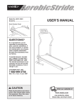
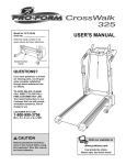
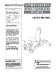
WARNING DECAL PLACEMENT
The decal shown here has been placed
on the weight bench. If the decal is
missing or illegible, please call our
Customer Service Department toll-free
at 1-888-825-2588, Monday through
Friday, 6 a.m. until 6 p.m. Mountain
Time, to order a free replacement
decal. Apply the decal in the location
shown.
• Misuseofthis product
mayresultin serious
injury.
• Readuser'smanual
and followall warnings
and operatinginstructions priorto use.
• Donotallowchildren
on or aroundmachine.
• Replacelabel if
damaged,illegible,or
removed.
NordicTrack is a registered trademark of ICON Health & Fitness, Inc.
2
IMPORTANT PRECAUTIONS
WARNING:
To reduce the risk of serious injury, read the following
important precautions
before using the weight bench.
1.
Read all instructions in this manual before
using the weight bench. Use the weight
bench only as described in this manual,
2.
It is the responsibility of the owner to ensure
that all users of the weight bench are adequately informed of all precautions,
3.
The weight bench is intended for home use
only. Do not use the weight bench in any
commercial, rental, or institutional setting,
4.
Use the weight bench only on a level surface.
Cover the floor beneath the weight bench to
protect the floor.
5.
Make sure all parts are properly tightened
each time the weight bench is used. Replace
any worn parts immediately.
WAR
NIN G:
6.
Keep children under 12 and pets away from
the weight bench at all times.
7.
Keep hands and feet away from moving parts.
8.
Always wear athletic shoes for foot protection while exercising.
,
The weight bench is designed to support a
maximum user weight of 300 pounds, and a
maximum total weight of 610 pounds. Do not
use the weight bench with more than 310
pounds of weight. Note: The weight bench
does not include weights.
10. If you feel pain or dizziness at any time while
exercising, stop immediately and begin cooling down,
Before beginning this or any exercise
program, consult your physician. This
is especially important for persons over the age of 35 or persons with pre-existing health problems.
Read all instructions before using. ICON assumes no responsibility for personal injury or property
damage sustained by or through the use of this product.
BEFORE YOU BEGIN
Thank you for selecting the versatile NordicTrack '_
STRENGTH AB BENCH weight bench. The weight
bench offers a selection of weight stations designed to
develop every major muscle group of the body.
Whether your goal is to tone your body, build dramatic
muscle size and strength, or improve your cardiovascular system, the weight bench will help you to
achieve the specific results you want.
toll-free at 1-888-825-2588, Monday through Friday,
6 a.m. until 6 p.m. Mountain Time (excluding holidays).
To help us assist you, please note the product model
number and serial number before calling. The model
number is NTB09920. The serial number can be found
on a decal attached to the weight bench (see the front
cover of this manual).
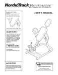
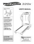
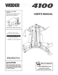
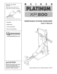
Before reading further, please review the drawing
below and familiarize yourself with the parts that are
labeled.
For your benefit, read this manual carefully before
using the weight bench, tf you have additional questions, please call our Customer Service Department
Ankle Pad
Knee Pad
Handle
Adjustment Knob
Backrest
Adjustment Knob
Wheel
4
PART IDENTIFICATION
CHART
Refer to the drawings below to identify small parts used in assembly. The number in parentheses by each drawing is the key number of the part, from the PART LIST on page 10 of this manual. Note: Some small parts may
have been pre-attached. If a part is not in the parts bag, check to see if it has been pre-attached.
M4 x 16mm Selftapping Screw (27)
M6 x 16mm Screw (22)
M10 x 63mm Button Head Bolt (25)
M10 x 70mm Carriage
M10 Washer
Bolt (23)
_
(24)
L
M10 Nylon Locknut
(26)
M10 x 75mm Button Head Bolt (32)
t\\\\\\\
M12 x 87mm Button Head Bolt (30)
M12 Nylon Lockut (13)
M10 x 115mm Carriage
Bolt (21)
ASSEMBLY
• Place all parts in a cleared area and remove the
packing materials. Do not dispose of the packing
materials until assembly is completed.
Make Things Easier for Yourself
This manual is designed to ensure that the
weight bench can be assembled successfully
by anyone. Most people find that by setting
aside plenty of time. assembly will go smoothly.
E
The included Allen wrenches and the following
tools (not included) are required for assembly:
• Two adjustable wrenches
Before beginning assembly, carefully read the
following information and instructions:
• One rubber mallet
• One standard screwdriver
'
• Assembly requires two people.
• One Phillips
• For help identifying small parts, use the PART
IDENTIFICATION CHART on page 5.
screwdriver
• Lubricant, such as grease or petroleum jelly,
and soapy water.
• Tighten all parts as you assemble them, unless
instructed to do otherwise.
Assembly will be more convenient if you have a
socket set, a set of open-end or closed-end
wrenches, or a set of ratchet wrenches.
• As you assemble the weight bench, make sure all
parts are oriented as shown in the drawings.
.
Before beginning assembly, make sure you
understand the information in the box
above,
Attach a Wheel (9) to the Stabilizer (2) with an
M10 x 63mm Button Head Bolt (25), an Axle (33),
an M10 Washer (24), and an M10 Nylon Locknut
(26). Repeat this step with the other Wheel.
.
Press a 50mm x 75mm Inner Cap (11) into the
Frame (1). Press two 38mm x 100mm Inner Caps
(12) into the top of the arms on the Frame.
21
12
Attach the Frame (1) to the Stabilizer (2) with four
M10 x 115mm Carriage Bolts (21), four M10
Washers (24), and four M10 Nylon Locknuts (26).
6
.
Press a 50mm Square Inner Cap (15) into the
end of the Backrest Frame (3).
Attach the Adjustment Arm (8) to the Backrest
Frame (3) with two M10 x 75mm Button Head
Bolts (32), two M10 Washers (24), and two M10
Nylon Locknuts (26).
Attach the two Finger Guards (7) to the Backrest
Frame (3) with four M4 x 16mm Self-tapping
Screws (27).
.
Attach the Adjustment Pin (18), the Threaded
Collar (29), the Spring (19), and the Backrest
Adjustment Knob (20) to the Frame (1).
Insert bolt
through this
hole
Engage the Adjustment Pin (18) into a hole in the
Adjustment Arm (8). Make sure the Adjustment
Arm is under the indicated rod.
/
3
Lubricate the M12 x 87mm Button Head Bolt (30)
with grease. Attach the Backrest Frame (3) to the
Frame (1), at the indicated hole, with the Bolt and
an M12 Nylon Locknut (13). Do not overtighten
the Locknut; the Backrest Frame must be able
to pivot easily.
.8
\
13
/
//,
?
//
// /'
/
1
/
20
.
Attach the Backrest (5) to the Backrest Frame (3)
with six M6 x 16mm Screws (22).
i
22
22
.
Press a 50mm Square Inner Cap (15) into the top
end of the Upright (4).
Attach a set of Pads (16, 31) to a Pad Bracket (6)
with four M6 x 16mm Screws (22). Make sure
the Pads and Pad Bracket are oriented as
22
23
22
Straight
Edge
shown. Repeat with the other set of Pads and
Pad Bracket.
Attach a Pad Bracket (6) to the top of the Upright
(4) with two M10 x 70mm Carriage Bolts (23), two
M10 Washers (24), and two M10 Nylon Locknuts
(26).
Attach the other Pad Bracket (6) to the indicated
side of the Upright (4) with two M10 x 70mm
Carriage Bolts (23) and two M10 Nylon Locknuts
(26).
31
Handle
s
Straight
Edge
.
Wet the handle on the Upright (4) with soapy
water. Slide the Handle Grip (28) onto the handle.
Slide the 60mm Square Bushing (10) onto the
bottom of the Upright. Make sure the tabs are
on the indicated sides.
Press the 55mm Square Bushing (14) into the
bottom of the Upright (4). Secure the Bushing
with two M4 x 16mm Self-tapping Screws (27).
Have one person press the tabs on the 60mm
Square Bushing (10) into the indicated hole in the
Upright (4) while a second person slides the
Upright and Bushing into the Backrest Frame (3).
Engage the tabs on the Bushing into the slots in
the Frame. Be careful not to pinch your hands
as you slide the Bushing into the Frame.
Thread the Upright Collar (34) into the Backrest
Frame (3). Pull the Upright Adjustment Knob (17)
out, and use a wrench to fully tighten the Collar
into the Backrest Frame. Engage the Knob into a
hole in the Upright (4), and tighten it fully.
.
Make sure that all parts are properly tightened
before you use the weight bench. The use of
all remaining parts will be explained in
ADJUSTMENTS, starting on the next page.
6
17
16
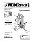
ADJUSTMENTS
This section explains how to adjust the weight bench. Refer to the accompanying
rect form for each exercise.
exercise guide to see the cor-
Make sure all parts are properly tightened each time the weight bench is used. Replace any worn parts immediately. The weight bench can be cleaned with a damp cloth and a mild, non-abrasive detergent. Do not use solvents.
ADJUSTING
THE BACKREST AND UPRIGHT
To adjust the angle of the Backrest (5), hold onto it
with one hand and pull the Backrest Adjustment Knob
(20) out. Move the Backrest to the desired position.
Reengage the Knob into the Adjustment Arm (8).
To adjust the height of the Upright (4) loosen the
Upright Adjustment Knob (17) and pull it out. Move
the Upright to the desired height and reengage and
tighten the Knob.
17
5
\
2O
PART LISTmModel
Key No. Qty.
No. NTB09920
Description
R0103A
Key No. Qty.
1
2
3
1
1
1
Frame
Stabilizer
Backrest Frame
21
22
23
4
14
4
4
5
6
1
1
2
Upright
Backrest
Pad Bracket
24
25
26
10
2
12
7
8
9
2
1
2
Finger Guard
Adjustment Arm
Wheel
27
28
29
6
1
1
10
11
12
13
14
15
16
17
18
19
20
1
1
2
1
1
2
2
1
1
1
1
60mm Square Bushing
50mm x 75mm Inner Cap
38mm x 100mm Inner Cap
M12 Nylon Locknut
55mm Square Bushing
50mm Square Inner Cap
Right Pad
Upright Adjustment Knob
Adjustment Pin
Spring
Backrest Adjustment Knob
30
31
32
33
34
35
#
#
#
#
#
1
2
2
2
1
1
1
1
1
1
1
Description
M10 x 115mm Carriage Bolt
M6 x 16mm Screw
M10 x 70mm Carriage Bolt
M 10 Washer
M10 x 63mm Button Head Bolt
M10 Nylon Locknut
M4 x 16mm Self-tapping Screw
Handle Grip
Threaded Collar
M12 x 87mm Button Head Bolt
Left Pad
M10 x 75mm Button Head Bolt
Axle
Upright Collar
Upright Adjustment Pin
User's Manual
Exercise Guide
Grease Packet
M8 Allen Wrench
M6 Allen Wrench
Note: "#" indicates a non-illustrated part. Specifications are subject to change without notice. See the back cover
of this manual for information about ordering replacement parts.
10
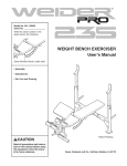
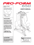
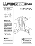
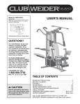
EXPLODED DRAWINGmModel
No. NTB09920
22
Ro_o3A
23
22
34
31
13 7
24
16
15
22
21
22
6
22
31
.26
22
15
22
16
29
25
20
33
)24
9
33
25
11
ORDERING
REPLACEMENT
PARTS
To order replacement parts, simply call our Customer Service Department toll-free at 1-888-825-2588, Monday
through Friday, 6 a.m. until 6 p.m. Mountain Time (excluding holidays). To help us assist you, please be prepared to give the following information:
1. The MODEL NUMBER of the product (NTB09920)
2. The NAME of the product (NordicTrack '_STRENGTH AB BENCH weight bench)
3. The SERIAL NUMBER of the product (see the front cover of this manual)
4. The KEY NUMBER and DESCRIPTION
of the part(s) (see pages 10 and 11 of this manual)
LI MITED WARRANTY
WHAT IS COVERED_The
entire NordicTrack '_ STRENGTH
defects in material and workmanship.
WHO IS COVERED--The
original purchaser
AB BENCH
weight
bench ("Product")
is warranted
to be free of all
or any person receiving the Product as a gift from the original purchaser.
HOW LONG IS IT COVERED--ICON
Health & Fitness, Inc. ("ICON"), warrants the product frame for five years after the date of purchase. ICON warrants all other parts for one year after the date of purchase. Labor is covered for one year.
WHAT WE DO TO CORRECT COVERED DEFECTS_We
will ship to you, without charge, any replacement part or component, providing the repairs are authorized by ICON first and are performed by an ICON trained and authorized service provider, or, at our
option, we will replace the Product.
WHAT IS NOT COVERED_Any
failures or damage caused by unauthorized
service, misuse, accident, negligence, improper
assembly or installation, alterations, modifications without our written authorization or by failure on your part to use, operate, and
maintain as set out in your User's Manual ("Manual").
WHAT YOU MUST DO--Always
retain proof of purchase, such as your bill of sale; store, operate, and maintain the Product as specified in the Manual; notify our Customer Service Department of any defect within 10 days after discovery of the defect; as instructed, return any defected part for replacement or, if necessary, the entire product, for repair.
USER'S MANUAL--It
periodic maintenance
is VERY IMPORTANT THAT YOU READ THE MANUAL before operating the Product. Remember
requirements specified in the Manual to assure proper operation and your continued satisfaction.
HOW TO GET PARTS AND SERVICE--Simply
call our Customer
Service Department
at 1-888-825-2588
to do the
and tell them your name
and address and the serial number of your Product. They will tell you how to get a part replaced, or if necessary, arrange for service where your Product is located or advise you how to ship the Product for service. Before shipping, always obtain a Return
Authorization Number (RA No.) from our Customer Service Department; securely pack your Product (save the original shipping carton if possible); put the RA No. on the outside of the carton and insure the product. Include a letter explaining the product or problem and a copy of your proof of purchase if you believe the service is covered by warranty.
ICON is not responsible or liable for indirect, special
formance of the product or damages with respect to
ment or use, costs of removal, installation or other
exclusion or limitation of incidental or consequential
or consequential
damages arising out of or in connection with the use or perany economic loss, loss of property, loss of revenues or profits, loss of enjoyconsequential
damages of whatsoever nature. Some states do not allow the
damages. Accordingly, the above limitation may not apply to you.
The warranty extended hereunder is in lieu of any and all other warranties and any implied warranties of merchantability
or fitness
for a particular purpose is limited in its scope and duration to the terms set forth herein. Some states do not allow limitations on how
long an implied warranty lasts. Accordingly, the above limitation may not apply to you.
No one is authorized to change, modify or extend the terms of this limited warranty. This warranty
you may have other rights which vary from state to state.
ICON HEALTH & FITNESS,
Part No. 192454 R0103A
INC., 1500 S. 1000 W., LOGAN,
gives you specific legal rights and
UT 84321-9813
Printed in China © 2003 ICON Health & Fitness, Inc.