1
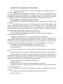
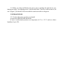
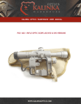
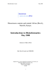
Kalinka Optics Warehouse
User Manual
www.kalinkaoptics.com
Kobra AK Side Mount Red Dot Sight Manual
CONTENTS
1.
2.
3.
4.
5.
6.
7.
8.
9.
10.
11.
12.
13.
14.
Introduction ........................................................... 4
Purpose .................................................................. 4
Specifications ......................................................... 4
Components and Equipment Provided ................... 5
Design and Operating Principles ............................. 6
General Information .............................................. 10
Preparing the Sight for Operation ........................... 11
Adjusting and Operating the Sight ........................ 13
Technical Inspection .............................................. 17
Troubleshooting .................................................... 17
Maintenance .......................................................... 17
Storage Rules ......................................................... 19
Package Certificate ................................................ 19
Acceptance Certificate ........................................... 20
1 INTRODUCTION
1.1 This document provides users with information about our sighting device design
and operating features.
2 PURPOSE
2.1 Our open-type collimator sight, AK side mount version, with electronic controls
for brightness and changeable sighting marks (objectives) is designed to enhance sighting
time and accuracy of hunting guns while shooting at various targets including fast
moving ones. The collimator sight allows firing under natural illumination conditions
from twilight to daylight.
2.2 The sight may be presently fitted onto any rifle with an AK side rail including
the Tigr, all versions of the Saiga, etc.
3 SPECIFICATIONS
Engagement distance - as far as a target can be observed
Field of vision ……………………………........unlimited
Reflector light transmission ratio …………...…......... 0.6
Angular size of the «dot»-type sighting mark .. 1.8 MOA
Conditional angular field of vision with the shooter's eye at 200 mm from the optical block
plane, no less than: .…..………………………………………….....6°
Time of continuous operation of sight with the "dot" mark (without replacing a battery) at
medium brightness under normal conditions .…………………………………... 70 h
Operating temperature ……………...….........-40 to +50°C
Dimensions .………………………….……...144x66x 144mm
Weight ………………………………………....…….410 g
Number of sighting mark types …………….………….....4
Supply voltage ………………...………….…3 V (1.5 V x 2)
4 COMPONENTS AND EQUIPMENT PROVIDED
4.1 The product includes:
Collimator sight ………………………………............ 1
Packing box .................................................................. 1
Case (hand bag) ......................................................….. 1
Wrench-screwdriver ...............................................…... 1
Lens hood ...............................................................…. on certain models
Cleaning cloth .............................................................. 1
Note: At an ambient temperature of- 10°C and lower you should use the finger-type
batteries LR6 (alkaline), e.g. DURACELL ALKALINE, SONY ALKALINE, etc.
5 DESIGN AND OPERATING PRINCIPLES
5.1 The sight consists of the following parts (Figure 1): body 1; reflector 2;
windage and side correction dial 3 (on the right); elevation and engagement distance dial
4; on-switch 5; mark selection button 6; mark brightness button 7; sight-to-gun fitting
arrangement 8; bracket 9; battery compartment cover 10.
Figure 1 - Sight ЭКП-1С-03
1 - elevation check nut, 2 - elevation lead screw, 3 - distance dial 4 - cap; 5 - sight body;
6 - cap; 7 - side correction dial; 8 - windage check nut, 9 - windage lead screw
Figure 2 - Windage and Elevation Dials
The digits on the side correction dial are conventional. The dial scale reads to 3-5
cm at the 100 m distance. The dials' indices stand for the following:
«СТП» - average point of impact
«П» - «СТП» shifted rightwards
«Л» - «СТП» shifted leftwards
«H» - «СТП» shifted downwards
«В» - «СТП» shifted upwards.
Figure 3 - Sight-to-gun fitting
arrangement
5.2 The sight-to-gun
fitting arrangement includes
(Figure3): body 1; adjusting
screw 2; movable block 3;
lever with eccentric 4; rest 5.
5.3 When power on, the signal is fed to a LED radiator located in the body 1 (Figure
1) forming a sighting mark (Figure 5). A shooter sees the sighting mark in the reflector
optical block 2 (sighting window) (Figure 1).
5.4 The sight operating principle is based on matching the luminous sighting mark,
e.g. "dot"-type, with the target seen through the optical block.
a) T-mark; b) « dot & pike»type mark; c) «pike»-type
mark; d) "dot"-type mark.
Figure 3 - Sighting Marks
5.5 To get optimum contrast of the target and the sighting mark under different
illumination conditions the sight includes a button 7 for mark brightness adjustment (Figure
1).
5.6 The specific features of open coliimator sight without magnification are:
- the sighting mark image is formed at infinity and so it can be observed as sharply as the
target;
- sighting and observing the target with both eyes simultaneously;
- when the eye moves within the sighting window the sighting mark is on the target and
shows the bullet hit location.
5.7 The collimator sight will switch on to the presdected mark type (button 6) and
brightness level (button 7), due to a memory feature (on-switch 5 in Figure l). This allows one
to preset an optimum type and brightness of the sighting mark.
5.8 Engagement distance is set and side corrections are entered by the dials 3 and 7
(Figure 2).
5.9 The dials 3 and 7 are protected against damages by the folding caps 4 and 6 (Figure
2) with 16 marks each for adjusting the sight.
6 GENERAL INFORMATION
6.1 Prior to operation, clean the body 1, the adjusting screw 2, the movable block 3, the
lever with eccentric 4, the rest 5, the heads of all screws (Figure 3) and the wrenchscrewdriver of lubricant with a cloth. Wipe the lenses with the cloth supplied with the sight
from their centres to edges with circular motions.
6.2 Test for proper operation:
- power on/off;
- free turning of the windage dial to the left and to the right against the stop and that of
the distance dial to the right against the stop;
- the sighting mark types and their brightness switches.
6.3 The sight is dust- and moisture-proof. All the threaded junctions are locked against
loosening. Disassembling the sight is not recommended because the sight assembly depends
on pre-torqued screws to guard against loosening. All disassembling operations must be
implemented by specially trained staff in our workshops.
7 PREPARING THE SIGHT FOR OPERATION
7.1 Batteries.
7.1.1 To install or replace batteries, turn the cover 10 of the battery compartment (Figure
1) in the «O» (open) direction with the wrench-screwdriver and pull it out from its socket.
Then remove the old batteries and install the new ones according to polarity given on the
bottom of the sight body. Place the cover 10 into its socket and turn in the «3» (closed)
direction until it stops.
7.2 Turn power on/off by turning the handle 5 (Figure 1) to the «B» (on) or the «O»
(off) positions. If the sighting mark is not seen upon switching on, we recommend
that you press the button 7 in the «+» direction several times or check if the batteries
are installed properly.
7.3 Select the mark (objective) type by consecutive pressing the button 6.
7.4 Set the optimum brightness of the mark with the button 7 (Figure 1). The button 7 is
a double-armed lever. A single push on one of the arms in the «+» or the «-» direction results
in brightness increase or decrease by a factor of two (each level is twice as bright as the
previous one).
7.5 Sight installation:
- prior to installation onto the gun, the rest 5 (Figure 3) of the sight fitting arrangement
should be directed towards the butt and pressed to the body 1;
- push the sight onto the side mounting bar which is located on the gun left side, from
the butt-stock side until it stops;
- turn the rest 5 to 180° to the barrel, at the same time bring the rest 5 lug over the body
1 while pressing the rest 5 downwards.
The sight should be fixed tightly on the gun's side bar. If necessary, adjust sight-to-gun
fixing. The following may occur:
- you cannot bring the rest 5 lug over the body 1 even with great force applied to the
rest 5;
- you have brought the rest 5 lug over the body 1 but the sight is not fixed tightly on the
gun's side bar.
If you cannot bring the rest 5 lug over the body 1, proceed as follows:
- turn the rest 5 to approximately 90° towards the butt. Turn the movable block 3 to
approximately 90° relatively to the rest 5, move it towards the hole and remove the block 3;
- not removing the sight from the gun, remove the rest 5 from slots of the adjusting
screw 2, mount the rest 5 while shifting it together with the lever 4 to some gears towards
the barrel (to decrease force applied to the rest 5);
- replace the block 3 with its locking lug down and inserting it into the hole on the rest
5. Bring the rest 5 lug over the body 1 while pressing the rest 5 downwards.
If th sight is not fixed tightly on the gun's side bar:
- shift the rest 5 together with the lever 4 to some gears towards the butt;
- replace the block 3 with its locking lug down and inserting it into the hole on the rest 5.
Bring the rest 5 lug over the body 1 while pressing the rest 5 downwards.
8 ADJUSTING AND OPERATING THE SIGHT
8.1 After first-hand acquaintance with the sight design and operating principle it is
necessary to sight-in your gun.
8.2 Sighting-in is accomplished at a distance of 100 m on a firing ground or in a
shooting gallery. The shooter should be in a reclining position or the gun should be fixed onto
an arming rest while shooting. Firing is with a sighting-in target cut out of paper or cardboard
with a black circle (0 25 cm) and a marked centre placed on a white board (1.0x1.0 m).
Note! The bull's eye should be the centre of a circle.
The sighting-in process consists of superposition of the luminous «dot» with the centre
of impact.
8.3 To sight-in the gun, some series of 4 shot groups are required. If the middle of your
groups is upper (lower) the target centre or to the left (right) of it, you should displace the
average point of impact downwards (upwards) or to the right (left) by a measured deviation
from the aiming point with the windage and elevation dials (Figure 2). Remember that the
scales on the caps 4 and 6 (Figure 2) read to 3-5 cm at 100 m.
The average point of impact (СТП) is determined as below:
- for every 4 shots when sighting at the target circle centre, the points of impact are
coupled with 2 skew straight lines;
- midpoints of the portions get are connected together with a straight line;
- a midpoint of this portion is the average point of impact. The sight is considered to be
sighted-in if the middle of your groups is inside the 10 cm circle in a centre of the target, with
a normal close grouping of shots. The grouping of shots is considered to be normal when the
target has 4 or at least 3 bullet-holes in a circle of 15 cm. Now the sight may be operated.
For adjustment of the sight when sighting-in, see Sections 8.4-8.7.
8.4 To make necessary vertical (elevation) corrections (See Figure 2):
a) remove the cap 4;
b) unscrew the check nut 1 by 1-2 turns with the wrench-screwdriver while holding the
dial 3;
c) lift the dial 3 with the screwdriver and detach it from the lead screw 2 tapered surface;
d) turn the lead screw 2 with the wrench-screwdriver in the direction of displacement of
average point of impact by the arrow on the dial 3 outside end, when you have closed the cap
4, to the cap 4 scale divisions which correspond to the vertical displacement of average point
of impact. Turn the screw slot 2 according to the division marks.
8.5 Upon vertical (elevation) adjustment (See Figure 2):
а) remove the cap 4;
b) align the dial 3 at the «0» position with the sight body fixed mark;
c) tighten the check nut 1 while pressing the dial 3 downwards, make sure that the screw
2 does not turn through;
d) close the cap 4. The digit «0» of the distance set will be seen through the window on
the cap.
8.6 To make necessary horizontal (windage) corrections (See Figure 2):
a) remove the cap 6;
b) unscrew the check nut 8 by 1-2 turns with the wrench-screwdriver while holding the
dial 7;
c) lift the dial 7 with the screwdriver and detach it from the lead screw 9 tapered surface;
d) turn the lead screw 9 with the wrench-screwdriver in the direction of displacement of
average point of impact by the arrow on the dial 7 outside end, when you have closed the cap
6, to the cap 6 scale divisions which correspond to the horizontal displacement of average
point of impact. Turn the screw slot 9 according to the division marks.
8.7 Upon horizontal (windage) adjustment (See Figure 2):
a) remove the cap 6;
b) align the dial 7 at the «0» position with the sight body fixed mark;
c) tighten the check nut 8 while pressing the dial 7 to the left and make sure that the
screw 9 does not turn through;
d) close the cap 6. The digit "0" of the correction set will be seen through the window on
the cap.
8.8 To apply a correction while operating the sight, turn the dial 3 (Figure 2) for
engagement distance and the dial 7 for windage.
Note: The dials 3 and 7 can be turned from one fixed position to another to the right or to
the left as far as they will go.
8.9 We recommend you not to remove the dials 3 and 7 because of a possibility of losing
the lock spring and the lock ball.
8.10 Set the switch 5 (Figure 1) to the «O» (off) position at the end of operation.
9 TECHNICAL INSPECTION
9.1 We recommend carrying out a periodic technical inspection in accordance with
Section 6 of this Manual. The technical inspection period depends on the sight's usage.
10 TROUBLESHOOTING
Table 1
Trouble
Possible Cause
Remedy
The mark does not go on
when the sight is on
Batteries are
discharged
Polarity is wrong
Replace batteries
Observe polarity
The mark is on
but brightness is poor
Supply voltage is
low
Replace batteries
11 MAINTENANCE
11.1 When you remove the sight from the gun and prior to packing it into its case,
examine the sight and wipe it with a clean tissue. The lenses should be cleaned from their
centres to edges with circular motions by the cloth supplied with the sight.
11.2 If the sight has been immersed into water, wipe and dry it.
11.3 When you clean and lubricate the gun or prior to packing the sight into its case,
lubricate the body 1, the adjusting screw 2, the movable block 3, the lever with eccentric 4, the
rest 5 (Figure 3), the heads of all screws and the wrench-screwdriver with grease.
12 STORAGE RULES
12.1 For the sight proper operation you should:
a) protect the sight from falls and shocks;
b) store it in dry heated premises at a temperature of+5° to +35° С and at a relative
humidity of up to 85%.