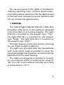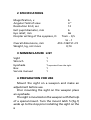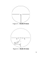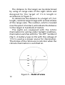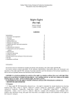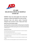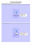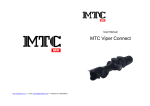
1
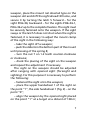
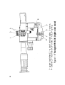
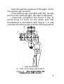
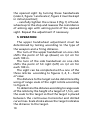
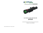
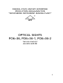
Federal State Unitary Enterprise
Production Amalgamation
“Novosibirsk Instrument-making Plant”
Optical Sights
PO6×36, PO6×36-1, PO6×36-2
Service manual
АL3.812.225 RE
Contents
Page
1 Purpose 5
2 Specifications 6
3 Nomenclature list 6
4 Preparation for use 6
5 Operation10
6 Maintenance and storage13
7 Safety13
8 Acceptance certificate14
The sights are the subject of continuous
development and improvement, consequently
there may be slight differences between the
product and the information given herein.
The service manual of the sights is intended for
studying operating rules, contains specifications,
information about operation with the sights as well
as the main rules, necessary to ensure operation and
full use of technical opportunities.
1 Purpose
The Optical Sights PO6×36, PO6×36-1, PO6×36-2
(hereafter referred to as the sight) are designed
to be mounted on a hunting weapon. The sight
PO6×36 is mounted on the weapon type “Tigr”,
the sight PO6×36-1 is mounted on the weapon
type “Saiga”, the sight PO6×36-2 is mounted on
the weapon type “Vepr”.
The sight features reticle illumination, allowing
for use under twilight conditions.
The sights are provided with two handwheels
with scales which make it possible to input the
required windage and elevation corrections during
adjustment of fire and shooting.
The sights are designed to operate in an open
air environment within a temperature range of
-40 °C to +40 °C and relative humidity up to 95%
at temperature + 25 °C.
2 Specifications
Magnification, x 6
Angular field of view
4°
Resolution limit, sec12
Exit pupil diameter, mm
6
Eye relief, mm
66
Diopter setting of the eyepiece, D
from – 0,5
to – 1
Overall dimensions, mm
410×136/151×72
Weight, kg, not more 0,74
3 Nomenclature list
Sight1
Wrench1
Eyeshade1 separated from the sight
Box 1
Service manual
1
4 Preparation for use
Mount the sight on a weapon and make an
adjustment before use.
Prior mounting the sight on the weapon place
an eyeshade.
The sight is mounted on the weapon with the help
of a special mount. Turn the mount latch 5 (fig.1)
aside up to the stop prior installing the sight on the
weapon, place the mount rail dovetail type on the
weapon slot and shift the sight ahead till home, and
secure it by turning the latch 5 forward – for the
sight PO6×36; backward – for the sights PO6×36-1,
PO6×36-2 up to the complete fixation. The sight must
be securely fastened onto the weapon. If the sight
sways or the latch 5 does not shut when the sight is
fastened, it is necessary to adjust the mount clamp
of the sight in the following way:
– take the sight off a weapon;
– push the slider 6 in the bottom part of the mount
until pressing of the spring 8;
– turn the nut 7 on 1-2 teeth counter-clockwise
or clockwise;
– check the placing of the sight on the weapon
and repeat the adjustment if necessary.
The sight on the weapon should be adjusted
after ranging with opened sight (foresight and
sighting). For this purpose it is necessary to perform
the following:
– fastened the sight onto the weapon;
– place the upper handwheel 1 of the sight on
the point “1”, the side handwheel 1 (fig. 2) – on the
point “0”;
– align the weapon by the opened sight placed
on the point “1” at a target at a distant of 100 m;
7
2
6
3
5
Figure 1 – The sight PO6×36 (right-side view)
1 – upper handwheel; 2 – scale of vertical angles; 3 – screw;
4 – tumbler; 5 – mount latch; 6 – slider; 7 – nut; 8 – spring
8
1
4
– look through the eyepiece of the sight, notice
the aiming sign position;
– if the aiming sign coincides with the aiming
point of the opened sight, the sight is adjusted;
– otherwise, untighten the screws 3 (fig. 1)
performing 1-2 turns on the upper and side
handwheels in accordance with figures 1, 2, and
coincide the aiming sign with the aiming point of
2
1
1 – side handwheel ;
2 – scale of windage adjustments
Figure 2 – The Sight PO6×36
(objective side view)
the opened sight by turning these handwheels
(scale 2, figure 1 and scale 2, figure 2 must be kept
in initial position);
– carefully tighten the screws 3 (fig.1) of handwheels up to the stop and reassess the coincidence
of aiming sign with aiming point of the opened
sight. Repeat the adjustment if necessary.
5 Operation
The upper handwheel adjustment must be
determined by testing according to the type of
the weapon and a firing distance.
The turn of the upper handwheel on one click
shifts the point of hit up (down) on 3,2 cm for
each 100 m.
The turn of the side handwheel on one click
shifts the point of hit right (left) on 3,2 cm for
each 100 m.
The sight can be completed with a one of the
three reticles according to figures 3, 4, 5 – Field
of view.
The distance to the target can be determined by
using of range scale of the sight reticle according
to figure 4.
To determine the distance according to range scale
of the reticle by the height of a target of 1,5 m, aim
the scale to the target so that the target is placed
between the continuous horizontal and dotted
curve lines. Scale stroke above the target indicates
the distance to the target.
10
Figure 3 – Field of view
Figure 4 – Field of view
11
The distance to the target can be determined
by using of range scale of the sight reticle and
designed for the target of 1.5 m length in
accordance to figure 5.
To determine the distance to a target of 1,5 m
length, combine target image with vertical strokes
of the range scale. The number, which is located
near the point of contact, will indicate the distance
to the target in hundreds of meters.
The sights are equipped with the reticle
illumination for aiming under twilight conditions,
illumination switches with the “On-Off” tumbler 4
(fig.1). A battery type A-316 with the voltage of
1,5 V is used as a power source for illumination.
The strokes of the reticle are in red color when the
reticule illumination is switched on.
100
1,5
200
300
400
500
12
Figure 5 – Field of view
6 Maintenance and storage
Protect the sights from physical damage.
Wipe the outer optical surfaces with a clean,
soft cotton fabric, remove oil spots and thin coats
with the cotton wool wet with alcohol.
Protect optical parts of the sight from the
scratches during storage and operation.
7 Safety
During the operation with the sight, insure the
mounting is securely attached to the weapon. If
the sight sways, it is necessary to adjust the clamp
of a mount as indicated in the part 4.
13
8 Acceptance certificate
The Sight PO6×36____, serial № ___________,
is manufactured in accordance with technical
documentation and is fit for operation.
Date of issue ________________________
Signatures __________________________
(stamp)
Federal State Unitary Enterprise
Production Amalgamation
“Novosibirsk Instrument-Making Plant”,
179/2, D.Kovalchuk,
Novosibirsk, 630049
Russia
14