1
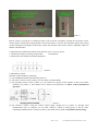
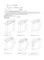
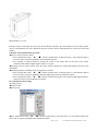
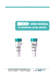
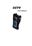
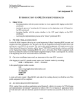
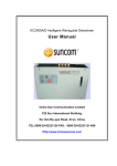
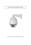
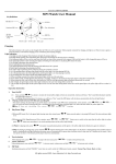
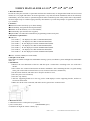
USER’S MANUAL FOR A3-1 15〞/17〞/19〞/21〞/22〞
1. Brief introduction:
In order to satisfy the customer’s requirement and meet the market trend, we designed this brand new lift for LCD
monitor. It is very light and features in artistic appearance, easy and convenient installation, and can be efficiently
controlled by one-to-one mode or optional integrated central controlled system. This product can be adjusted the
elevation angle easily to avoid the light go directly into human’s eye under the principle of ergonomics, to reduce
eyes’ tiredness.
2. Features:
◆Motorized control and freely up or down running;
◆God reliability, and good anti-shock performance;
◆Suitable for LCD monitors (15/17/19/21/22inch);
◆Automatically open and close the top panel;
◆Optional RS- 232 or RS-485 communicate programming control serial-ports.
3. Parameter requirements:
◆LCD Size:
◇For LCD 15〞: the displayer less than 375X60X320mm;5KG
◇For LCD 17〞: the displayer less than 395X65X350mm;5KG
◇For LCD 17〞W: the displayer less than 470X65X350mm;5KG
◇For LCD 19〞: the displayer less than 435X65X380mm;6KG
◇For LCD 19〞W: the displayer less than 450X80X380mm;6KG
◇For LCD 21〞: the displayer less than 490X85X370mm;6KG
◇For LCD 22〞W: the displayer less than 520X85X370mm;6KG
◆Power: AC220V, 50HZ (Or custom-made)
4. The place to be used:
This product is suitable for high-class multimedia meeting system, surveillance system and high-class multimedia
office, etc.
5. Installation:
◇Measure the exact dimension of the lift. And then open a conuter-bore according to the size of the lift’s
cabinet.
◇Have all the wire connected and run the lift before installation. After confirming the lift is in good running
status, pull out all of the connected wires (VGA, electrical source line, manual line);
◇Put he lift into the hole, and make sure to keep the surface be level;
◇Have the power wire connected;
◇Press the “Up” button;
◇After the supporting board rise to the top, put the LCD displayer on the supporting bracket, and have it
screwed on the bracket.
◇Make sure all the wires connected, and make sure the ground wire connected well.
6. Direction for use:
6.1 Illustration for the socket panel (as picture 1):
1-power socket(1PC)
2-RS485PORT (3pcs)
3-red button for login the remote control (1pc )
PAGE: 1 OF 5
COPY RIGHT: KMP TECHNOLOGY CO. LTD
Picture 1
Remote control: pressing the red learning button on the LCD lift, meanwhile pressing the last button on the
remote control ,releasing the learning button on the LCD lift after 2 seconds. The instruction light will be turned
on then releasing the last button on the remote control. The antenna of the remote control is adjustable which can
add the control distance.
6.2 Illustration for manual film control switch pad (The pad is on the top panel):
1, 2-Button for raising or lowering LCD monitor
3-Stop Button
4, 5-Button for LCD monitor inclination adjustment.
Picture 2
6.3 Methods of control:
Optional Control methods as following:
(1) By standardized manual film button(as picture 2)
(2) By unit set wireless remote control; you can control a lift individually.
(3) By grouping wireless remote control, you can control five groups of lifts together at most with remote
controller. (As picture 3) (The details can be found in the instruction of remote control disembarked
operation)
Picture 3
(4) By collective control. Using the romote control signal sending box (as picture 4), through serial
communication port of computer, you can make collective control on many groups of lifts by order.
Controlling communication is serial-port connect.( the details can be found in centralized control setting)
PAGE: 2 OF 5
COPY RIGHT: KMP TECHNOLOGY CO. LTD
Picture 4
(5) By terminal grouping wireless remote control (centralized remote control): you can make control by
connecting optional central control system with the help of programmed transmission control protocol. ( the
details can be found in the data pattern of RS-232 remote controller)
7. Standard Accessories:
◆1. Manual control cable and button
one set
◆2. Power cable
one item
8. Size of the lift:
Model number: A3-1 15”
Model number: A3-1 19”
Model number: A3-1 17”
Model number: A3-1 19W”
PAGE: 3 OF 5
Model number: A3-1 17”W
Model number: A3-1 21”
COPY RIGHT: KMP TECHNOLOGY CO. LTD
Model number: A3-1 22”
Remark: because some light warp caused by the production procedure, the actual dimension of the final product
may be a little different, the above dimension only for reference. Please install the lift base on the size of the final
product.
9. Remote control debarkation operation:
◆Unit set wireless remote control:
◇Press manual film switch “▲”“■”buttons synchronously, at that time there is a red indicator light in
the back of the case glisten gradually. Then unlash the buttons.
◇Use cartridge or small screwdriver pressing the switch in the emitter hole on the back of the remote
controller. If the indicator light bright steadily, it is in gear.
◆Grouping wireless remote control: Press the group selection button first; which light bright means the group
disembarks.
◆Eliminating former controlling code, the operation as follows:
◇Press manual film switch “▲”“■”buttons synchronously, at that time there is a red indicator light in
the back of the case glisten gradually. When the light glistens speedy, unlash the buttons.
◇Press manual film switch “▲”“■”buttons synchronously again, if the indicator light bright steadily, it
means the former code eliminated successfully.
10. Centralized control setting
Operating process:
◆Choose COM
◆Select group
◆Press manual film switch “▲”“■”buttons synchronously, at that time there is a red indicator light in the
back of the case glisten gradually. Then unlash the buttons.
PAGE: 4 OF 5
COPY RIGHT: KMP TECHNOLOGY CO. LTD
◆Cursor hit the button of setup learning (indicator light bright steadily means the operation is ok).
11. The data pattern of RS-232 remote control:
Set-up of RS-232 COM port: 2400, N, 8, 1. Means: 2400 baud, parity none, 8 data bits, one stop bit. A data string
has to send out more than 4 times continually.
Control codes
Explanation
An
Log on code:n=0~f,1~f are the designated group numbers,n=0 means complete control
Cn
Stop code:n=0~f,1~f means the designated group numbers,n=0 means complete control
Dn
Lifting code:n=0~f,1~f means the designated group numbers,n=0 means complete control
En
Lowering code:n=0~f,1~f means the designated group numbers,n=0 means complete control
12. Malfunction and elimination:
(When new installation or used motorized lift has malfunctioned and need to check by yourself, the first thing you
should do is contact with our company and then checks it after our permission.)
◆move less
◇Check the electrical source terminal and make sure the voltage in gear or not. If not you should check power
supply circuitry.
◇If the electrical source in gear please check whether the button tie wire loose or not; The fuse is in good
condition or not; switch line of upstroke and stroke down are loose or not.
◇Lift still in the upper point and can not down, please check whether the switch blocks or not.
◆Press both up and down buttons could not work, but hear quiver sound and it is not strong.
◇Check whether the capacitor punctures or not; Short circuit and the tie wire contact good or not. At that time
the motor will fever severely, please cut out the electrical source lest burnout motor.
◆Both up and down can move, but the machine emit strong noise.
◇Check transmission gear or rack if it is locked of the gear cracking;
◇Check gear and rack’s joggle to make sure if mal-position or not;
◇Check rack shaft liner if it is fell off or not;
◇Check gear and rack’s clearance to make sure if it is supper-big or not.
PAGE: 5 OF 5
COPY RIGHT: KMP TECHNOLOGY CO. LTD