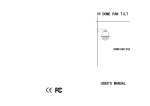
1
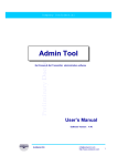
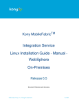
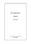
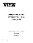
User’s Manual for Constant Speed Dome Camera
Please read the manual carefully before installing and using the unit.
Table of Contents
Part I: Introduction
1.1 Instructions ---------------------------------------------------------------------- 3
1.2 Characteristics ----------------------------------------------------------------- 4
1.3 Main Technical Data --------------------------------------------------------- 5
1.4 Installation method and ancillary components ------------------------ 6
Part II: Installation procedures
2.1 Out shape and installation size ------------------------------------------- 7
2.2 Installation of the camera -------------------------------------------------- 11
2.3 Connection of the camera and the housing --------------------------- 13
2.4 Installation of the transparent cover ----------------------------------- 16
2.5 Installation of the Housing and the Bracket -------------------------- 19
2.6 Installation of the Bracket ------------------------------------------------- 20
2.7 Fix the 7” and 9” Dome Camera ---------------------------------------- 22
2.8 Fix the 7” and 9” Semi Dome Camera -------------------------------- 23
2.9 Connecting Power cables and signal cables ------------------------ 25
Part III: Setup of the Functions of the dome camera
3.1 Setup of Communication ---------------------------------------------------------27
3.2 Power on and Working state examination --------------------------------- 34
3.3 Table of the Setup of the functions --------------------------------------------34
3.4 Set up and Preview the preset positions ----------------------------------- 35
3.5 Setup and running of Tour group --------------------------------------------- 36
3.6 Setup and running of Left and Right scanning------ ---------------------- 38
3.7 Start of the Pan/tilt’s 360° scanning ----------------------------------------- 38
1
3.8 Stop of the Auto Scanning ----------------------------------------------------- 43
3.9 Setup, Activating and Exitting of Default Position function ------------- 42
Part IV: Appendix
4.1
Constant temerature devices connecting sketch 1 ------------- 43
4.2
Constant temerature devices connecting sketch 2 ------------- 44
4.3
Trouble Shooting Table------------------------------------------------- 45
Part I: Introduction
1.1. Instructions:
We greatly appreciate your choosing our product!
As stated in the warranty instruction, when a breakdown occurs to
the properly used product, the product under warranty will be granted
free maintenance or spare parts replacement. Do not dismantle and
repair the unit without the company’s authorization.
Within one year from the purchase date, if any damage or
breakdown occurs to the product (excluding housing, bracket and
external wires) when it is properly used, we will provide free maintenance
or spare parts replacement after our technician confirms the case.
No free maintenance under the following circumstances:
1.
Damage or breakdown arising from the dismantling and repairing of
the unit without the company’s authorization;
2.
Damage or breakdown arising from the transportation, loading or
unloading of the unit which is arranged by the customer;
2
3.
Damage or breakdown arising from using and maintenance of the
unit without observing the instructions in the User’s Manual, including
damage or breakdown arising from crashing, crushing, and unit affected
with damp, liquids, corrosive or other man-made causes;
4.
Damage
or
breakdown
arising
from
inapplicable
ambient
temperature or overloaded operation; surface abrasion or damage
emerging when the unit is being used;
5.
Damage or breakdown arising from natural disasters and other
accidents.
Attention: To realize all the functions of the unit, a compatibility test must
be carried out before applying other manufacturer’s spare parts in the
system.
The Characteristics of Constant Speed Dome Camera:
1. Precise conductive slip-ring is adopted, with which pan 360° endless
running is realized and all-direction monitoring effect is realized,
cable-twisting problem as well as merely 355° pan problem which
generally happen with common constant speed domes are effectively
solved.
2. The operation is based on advanced stepper motors and driving
circuits,
which ensures smooth running, long time consecutive working,
long lifespan and high reliability.
3. PCB board is very compact, most of the parts on the PCB board are
highly integrated and modulized, thus the possibility of trouble is greatly
reduced and the stability of the performance is ensured.
4. The design of the outer housing of the Constant Speed Dome Camera
is reasonable, elegant and practical. The outer housing can endure
long-term operation without distortion. And the installation of the unit is
fast, convenient and more human.
3
5. The function of Position Limiting is realized with photoelectrical
sensors, which avoids the limitations of traditional mechanical Position
Limiting and switch Position Limiting (the lifespan of the switch is 200
thousand times ON/OFF).
6. Left/right limiting positions can be set up on the dome camera panel, it
also can be set up through the keyboard in the controlling room, which
avoids the limitations that the limiting positions can be only set up from
the front terminals for common constant speed domes.
7. There are 4 levels of running speed optional for the unit: 6°,
9°,12°,15°/S, which can be adjusted according to actual conditions.
8. The built-in PCB panel supports multi mainstream protocols, and many
more protocols can be input according to the customer’s needs. The
Baud rate is also adjustable.
9. The unit adopts DC14V(15V) power supply and separates from it the
components that produce heat in the process of transformation, which
prolongs the durability of the unit. The unit possesses the functions of
anti-jamming and anti-crashing.
10. Two grades anti-lightening technology, which effectively improve the
anti-lightening and anti-interruption ability
11. If the unit is carrying out scanning or cruising function when the
power is off, it will automatically resume carrying out the function once
supply of power is on after the power-off state.
12. Support 16 preset positions, 1 tour, left & right scan, 360° scan.
13. The unit has one default position; the user can preset the default
position for a key monitoring area according to the actual conditions. If
not operated after 5 minutes, the dome camera will automatically monitor
the preset position.
4
Remarks:The function of item 13 can be realized only when the protocol
adopted supports the keyboard produced by this company. Also, the user
can include our protocols into the DVR or existing software.
1-3. Main Technical Data:
1.
Electric Index
Power supply
DC14V---15V (2A)
Dome motor
DC14V---15V/0.5A
Camera lens motor
DC12V/100mA
Camera power supply
12V/1A
Temperature controlling devices ambient
Fan(≤50℃); heater (≥5℃)
Addresses range
1~63
Communication system
RS485 bus controlling
Communication protocol
supporting multi protocols
Baud rate
1200bps, 2400bps, 4800bps, 9600bps adjustable,
1200bps can be replaced by 19200bps as per
customer’s needs
Controlling device
video matrix, hard disk video recorder, DVR controlling
keyboard
Peset position quantity
16 preset positions
Auto Scan
Support Left&right scan and 360° scan
Tour group quantity
1 group(16 preset positions can be included)
Default position function
Yes
2.
Mechanical Index
Dome movement
pan 360° endless, tilt 0°-90°
Dome speed
pan/tilt, Pan 6º/S, 9º/S, 12º/S, 15º/S adjustable
Movement limiting position
pan adjustable within the dome movement scope
Maxium acceptable size of the compatible
Nine-inch Constant Speed Dome Camera:
5
video camera and lens
170(L)×80(H)×70(W)mm
Seven-inch Constant Speed Dome Camera
140(L)×70(H)×70(W)mm
3.
Ambient Index
Ambient temperature
0ºC~49ºC (without temperature controlling devices)
-35ºC~49ºC (with temperature controlling devices)
Relative Humidity
≤90%RH
1-4. Styles of Installation and Ancillary Components (See Table 1)
Table 1: Styles of Installation and Ancillary Components
Product
The style of installation
Bracket
Power
Ancillary
cables
components
(with
temperature-
connect
controlling device
Nine-inch
Outdoor
Seven-inch
Outdoor
Nine-inch
Indoor
Seven-inch
Indoor
Wall-mount installation
Pendant-mount installation
Pendant-mount installation
Wall-mount installation
Ceiling-mount installation
Ceiling-mount installation
or)
Wall-mount bracket
DC14V(15V)/2A
Bracket length:
20cm or 40cm
power
Bracket length:
20cm or 40cm
DC14V(15V)/2A
Wall-mount bracket
prepared
by
the
temperature is below
0℃ or above 50℃
No bracket;
Steel wire rope to be
Required when the
cable
video
cable
RS485
cable
DC14V(15V)/2A
user
Part II: Installation Procedures
2-1. Outer shape and installation size.
1. Dimensions of Nine-inch Constant Speed Dome Camera
6
2. Dimensions of Double-layer Housings of Nine-inch Constant Speed
Dome Camera
7
3. Dimension of Seven-inch Constant Speed Dome Camera
8
4. Dimension of the Semi-dome of Nine-inch Constant Speed Dome
Camera
9
5. Dimensions of the Semi-dome of Seven-inch Constant Speed Dome
Camera
10
2-2. Installation of Video Camera
1. Firstly make sure the size of the selected video camera is within the
acceptable range. Then follow the direction indicated on the camera
suspender, and fix the camera to it with special screws. Make the length
in the front and the back of the camera equal (D1=D2). (Refer to the
figure below.) Observe if there is any collision or friction between the
camera and the vitreous cover. If there is any, adjust the camera.
11
2. Connect Lens Controlling Cable
Camera Lens Controlling Cable should be provided by the camera
supporter.
Connect the camera controlling cable well according to the
corresponding relationship between the camera and the outlet of PCB
panel shown in the following table.
Controlling signal of the camera lens
Corresponding outlet on PCB panel
Camera power supply
+12VDC, GND
Lens Zoom
ZOOM
Lens Focus
FOCUS
Lens Iris
IRIS
Lens Controlling public ground
COM
3. Connect Video Cable
Connect BNC video outlet with the video output outlet of the
camera, then use the binding wire to tie the video cable inside the
12
camera and the lens cable into the hole beside the lens connecting outlet
on the PCB panel. After installing the camera, please set up
communication protocol, Baud rate, address, etc.
2-3. Connection of the Camera and the Housing of Dome Camera
Install the well-setup module equiped with camera into the housing.
Procedures shown below:
Step 1
Push the connecting ports end of the power, video and controlling
integrated cable through the central hole of the peg-board, and then fix
the connecting ports into the socket on the module. Then fit the parts
shown with dotted lines on the module into the indentation shown with
dotted lines on the peg-board. (See the above figure)
13
Step 2
Hold the module, then turn it to the direction as the arrow sign for
about 50 degrees till it can not move forward any longer, make sure the
three installing pegs are in right positions. (See the above figure)
14
Step 3
After the module is in right position, tighten the special screw (the
screw will not drop even when it is loosed to the end) manually or with a
screwdriver. Be sure the screw is tight, otherwise, the module might fall
when the unit is running. Installation of the camera completed. (See the
above figure)
Attention: Once the module is installed well with the housing, please
don’t merely pull the power, video and controlling integrated cable to lift
the unit, with which operation the connecting ports of the integrated cable
may be pulled out, or even worse, the connecting ports may be damaged
permanently. The right operation method is: hold the whole housing in
your palms, then continue with the installing and connecting work.
15
2-4. Installation of Vitreous Cover
1. Installation of the Vitreous Cover of Nine-inch Dome Camera
Put on the gloves and fit the point signed on the vitreous cover to the
corresponding one on the housing, then turn it to right for about 30
degrees till it can not move ahead any longer. (See the above figure)
2. Installation of the Vitreous Cover of Seven-inch Dome Camera
16
Put on the gloves and fit the vitreous cover to the housing well in
right position, then tighten the two screws manually or with a screwdriver.
(See the above figure)
3. Installation of the Semi-dome Vitreous Covers of Seven-inch and
Nine-inch Dome Camera
17
Put on the gloves and fit the three plastic pegs on the vitreous cover
to the corresponding ones on the housing, then turn it to the right for
about 20 degrees till it stops moving. (See the above figure)
Remark: The installing method for the vitreous cover of 7” semi dome
camera is the same as that of 9” semi dome camera. Thus only the
installing sketch for 7” semi dome camera is shown in this manual.
18
2-5. Installation of the Housing and the Wall-mount Bracket of Dome
Camera
Push the power, video and controlling integrated cable through the
bracket hole, then direct the top of the housing to the bracket hole and
tighten them. Use a screwdriver to drive the three M6 screws on the
bracket into the screw slot. (See the above figure)
19
2-6. Installation of the Bracket of Constant Speed Dome Camera
1.
Installation of Wall-mount Bracket of Outdoor Nine-inch (Seven-inch)
Constant Speed Dome Camera
Figure 1: Dimension of the installing bottom board of the Wall Bracket for
Outdoor Nine-inch (Seven-inch) Constant Speed Dome Camera
Select the desired installing location and make sure the place for
the dome camera installation can sustain its weight. Pencil the relative
positions of the four φ7.5 bores of the wall bracket on the wall, and fix the
bracket on the wall with particular screws (prepared by the user). (See
the above figure)
The wall bracket of the outdoor nine-inch constant speed dome
camera has the same dimension as the seven-inch, as shown above.
2. Installation of Bracket for Pendant-mount Outdoor Nine-inch
(Seven-inch) Constant Speed Dome Camera
20
Figure 2: Dimension of Bracket of Pendant mount Outdoor Nine-inch
(Seven-inch) Constant Speed Dome Camera
Select the desired location and make sure the place for the dome
camera installation can sustain its weight. Pencil the relative positions of
the three bores of the bracket on the ceiling, and fix the bracket to the
ceiling with special screws (prepared by the user). Do not forget to push
the connecting power, video and controlling cables through the cable
outlet into the bracket tube in advance.
The bracket of Pendant-mount outdoor nine-inch constant speed dome
camera has the same dimension as the seven-inch. See Figure 2.
Special Instruction: Pendant-mount bracket is used for indoor
installation. In some special condition if it is needed to be used outdoors,
in order to prevent the rain water from seeping into the unit and affecting
the normal running, please pay attention to the following points in the
installation project:
21
1.
The diameter of the flange on the outdoor vertical pole should be at
least 20cm more than that of the installing flange of the
Pendant-mount bracket.
2.
The cable should not go through the cable-slot on the flange edge of
the Pendant-mount bracket, it should go through the central hole of
the bracket.
3.
The 3 bolts fixing position should be sealed with sealant to prevent
the rain water from seeping in.
2-7. Fix the Seven-inch and Nine-inch Dome Camera
Step 1
Put the power adaptor into the well connected wall bracket and pin
the power adaptor with the power pinning board lest the power adaptor
slides out. (See the above figure)
22
Step 2
Pull the power, video and controlling integrated cable out of the
bracket tube via the cable out-going slot, then fit the dotted-line part of
the bracket shown in the figure to the two corresponding pegs on the
installed peg-board, then push the bracket downward until it locks in
place. Make sure the bracket fits well with the bracket installing bottom
board, then tighten the Tightening Screw on the bracket. (See the above
figure)
2-8. Installation of Seven-inch and Nine-inch Semi-dome Camera
Locations with suspended top suit the dome camera with in-ceiling
installation style, which appears to be a hemisphere, having elegant-look
and good concealment. The in-ceiling style installation applies to solid
locations of the ceiling. First, select the desired location, pencil the
outline
of
the
upper
housing
on
the
ceiling
and
make
a
corresponding-size bore(about 210mm diameters for Seven-inch Dome
Camera, about 240mm diameters for Nine-inch one), then insert the
23
upper housing into the ceiling, and press the spring pinning boards
against the edge of the ceiling opening. After that, tighten the screw
adjusting the spring pinning boards, and lock the upper housing in the
ceiling tightly. For the sake of better safety, please use a metal wire rope
to connect the top of the upper housing to a reinforced structure of the
ceiling. (The wire rope is required to bear at least 5 times the weight of
the dome camera.)
Remark: The installation for 7 inch Semi-dome Camera is the same as 9
inch one, thus only the installation sketch for 9 inch Semi-dome Camera
is shown in this manual.
24
2-9. Connecting Power Cable and Signal Cable of the Dome Camera
The connection of cables begins with the completion of installation.
1. The Application of Cables
Table 2
Cable
Application
4-strand cable
Video cable
Power cable for
temperature
controlling device
Camera
lens
controlling cable
Connecting objects
DC14V(15V)
Decoding PCB Board —
power supply
Power Supply Adaptor
485 controlling
Decoding PCB Board-
signal
controlling device
Camera signal
Camera-monitoring device
DC14V(15V)
Temperature controlling
power supply
device-power supply adaptor
Camera lens/
power control
Remarks
Power outlet
Green+ whiteBNC connector
Parallel connection with
the power supply of
Decoding PCB Board
Provided with the
Decoding PCB Board-camera
integrated camera
(including power cables)
2. Connection of Power Cable and RS485 Cable
Please connect the plug of the 220V adapter provided by this
company to the already existing AC220V power source, then connect the
14V(or 15V) output outlet of the adapter with the power input port of the
module. Directly link the 485 controlling cable with the 485 port of the
module, the green for 485+ while the white for 485-.
3. Connection of the Cable for Temperature Controlling Devices
If the selected product has temperature controlling device, two kinds
of power supply is acceptable: 1. DC14V(15V), 2. AC24V—26V. Users
25
can choose according to the condition. Please refer to the connecting
sketch of the Temperature Controlling Devices for the connection.
4.
Connection of Video Cable
Please weld a BNC connector to the already installed video cable,
and then make a connection to the video outlet provided by this
company.
Now, all the power cables and signal cables have been connected.
Please check carefully to guarantee correctness and firmness of all
connections.
Part III: Set up the Functions of the Camera
3.1 Setup of Communication Protocol, Baud Rate, Address and
running speed of Constant Speed Dome Camera
The speed dome has built-in Decoding PCB Board, the Address,
Protocol and Baudrate must be set up through the Decoding PCB Board,
so that the control of the dome and camera lens can be realized.
1.
Address Setup
As shown in the figure below, DIP-1 to DIP-6 of the 8-button coding
switches is used to set up address of the dome camera from 1 to 63.
Control can be realized only when address code of the dome camera is
identical to that of the hard disk video recorder or matrix or controlling
keyboard. The coding switches from DIP-1 to DIP-6 are equivalent to a
6-bit binary figure. The state “ON” of each bit means “1”
while”OFF”means”0”. Table 2 shows states of coding switches.
26
1- - 6 Addr ess Sel ect Swi t ch
7、8 Baud Rat e Sel ect Swi t ch
Key f or Lef t Posi t i on Set up
Key f or Dome Speed adj ust ment ( 5- 6)
Pr ot ocol Sel ect Swi t ch( 1- 4)
Key f or Ri ght Posi t i on Set up
J1
FOCUS
ZOOM
DI P
123456
12345678
Posi t i on Set up
I ndi cat or
J14
Lens common t er mi nal
I RI S
ON
J13
Camer a power +12V
Camer a power GND
ON DI P ON
Position
485 I nput
Setup
Power suppl y out
Indicator
Power i ndi cat or
Switches of the Decoding PCB Board
27
Table 3:Correspondence of Address and Coding Switches
No.
654321
No.
654321
No.
654321
No.
654321
1
000001
17
010001
33
100001
49
110001
2
000010
18
010010
34
100010
50
110010
3
000011
19
010011
35
100011
51
110011
4
000100
20
010100
36
100100
52
110100
5
000101
21
010101
37
100101
53
110101
6
000110
22
010110
38
100110
54
110110
7
000111
23
010111
39
100111
55
110111
8
001000
24
011000
40
101000
56
111000
9
001001
25
011001
41
101001
57
111001
10
001010
26
011010
42
101010
58
111010
11
001011
27
011011
43
101011
59
111011
12
001100
28
011100
44
101100
60
111100
13
001101
29
011101
45
101101
61
111101
14
001110
30
011110
46
101110
62
111110
15
001111
31
011111
47
101111
63
111111
16
010000
32
100000
48
110000
Protocol KRE-301 for KODICOM card hard disk video recorder, protocol
PELCO-D and RM110 for Shanghai Chengfeng hard disk video recorder
all adopt the hexadecimal system, which is different from other protocols
adopting decimal system, so the address should be converted into
decimal system. For details, please see Table 4.
28
Table 4:Correspondence of Hexadecimal Address and Coding Switches
No.
654321
No.
654321
No.
654321
No.
654321
1
000001
5
000101
9
001001
13
010011
2
000010
6
000110
10
010000
14
010100
3
000011
7
000111
11
010001
15
010101
4
000100
8
001000
12
010010
16
010110
Please set up coding switches according to Table 3 or Table 4 as per
the address you defined by yourself.
2. Communication Baud Rate Setup
As shown in the above figure, DIP-7 and DIP-8 of the 8-button
coding switches are used to set up Baud rate of communication and 4
different Baud rate can be selected (1200BPS/2400BPS/4800BPS/
9600BPS). Following table shows states of coding switches of baud rate.
The state “ON” of each bit means“1”, while”OFF”means”0”. Table 5
shows states of correspondence of Baud rate and coding Switches.
Table 5:Correspondence of Baud Rate and Coding Switches
Coding switches
1200 bps
2400 bps
4800 bps
9600 bps
No. 7
OFF
ON
OFF
ON
No. 8
OFF
OFF
ON
ON
Please set up the code according to Table 5 based on the protocol
applied.
3. Protocol Setup
As indicated in the above figure, DIP-1 to DIP-4 of the 6-button
coding switches are used to set up protocol of the dome camera. The
built-in Decoding PCB Board provides protocols as listed in Table 6.
Other protocols can also be written-in as the user requires.
29
Table 6: Correspondence of Coding Switches and Protocols.
No.
DIP- 4,3,2,1
Types of Protocols
1
0000
PELCO_D
2
0001
PELCO_P
3
0010
VICON
4
0011
PELCON
5
0100
KALATEL-312
6
0101
CCR-20G
7
0110
ADR-8060
8
0111
HY
9
1000
M800-CIA
10
1001
PANASONIC
11
1010
LILIN
12
1011
KRE-301
13
1100
WISDOM
14
1101
RM110
15
1110
JCO
16
1111
PELCO_D1
The built-in Decoding PCB Board provides the above fourteen
protocols. More protocols can also be provided as the user requires,
such as:
Communication protocols with matrix: SAMSUNG, KLT Matrix,
TDTC Matrix, PELCO Matrix, VICANYX Matrix and LP Matrix.
Communication protocols with hard disk video recorder: CNEUOL
embedded, Enterasys embedding, DM embedding, Hikvision embedding,
KCL, YAAN, SAMSUNG, KIDICOM-SX. For information of hard disk
video recorder protocols and Baud rate, please refer to Table 7.
Communication protocols with keyboard: Vido keyboard, PWT
keyboard, Samsung keyboard and YAAN keyboard.
30
Table 7: Reference for Hard Disk Video Recorder Protocols and Baud
Rate
KOMSA series hard disk
PELCO-D 2400,RM110 9600,HY 9600
MPG4 card of Viewse software
HY
MPG4 card of Shanghai Chenova
software
9600,PELCO-D
2400,RM110
9600
PELCO-D 2400,RM110 9600
KODICOM hard disk
PELCO-D 2400,LILIN SD 9600,KRE-301 9600
PICO
PELCO-D,KTD-312,VICON, etc,BAUD rate adjustable
PICASO hard disk
PELCON 2400,PELCO-D 2400,CCR-20G 4800
MPG4 card of DVTECH Software
ADR-820 4800
MPG4 card of zhongjiatianwei Software HY 9600,PELCO-P 2400
TMvideo card(Chengdu Kony)
M800-CIA
2400
MPG4 card of Yinhe software
PELCO-D 2400,WISDOM 4800
Please choose appropriate communication protocols according to
the protocols adopted by dome camera controlling equipment (such as
matrix,
HD
compatibility
video
test
recorder,
of
keyboard).
controlling
and
Before
installation,
a
controlled
equipment
is
recommended.
To control the three alternative camera lens of KODICOM HD video
recorder, please adopt KRE-301 protocol. Operation is shown below:
Switch on the “POWER” button on the top of the controlling
interface and press the focus button, then the state is Iris control.
Switch off the “POWER” button, and press the focus button, then it will
resume to focus control.
31
4. Set up the Movement Speed of the Dome
The movement speed of the dome can be set up through the coding
switch.
DIP 5 and DIP6 of the 6-button coding switch (see figure above) are used
to set up the movement speed of the dome. Please refer details as Table
10.
Table 8
No.
DIP: 5 6
Circling speed
1
00
6°
2
10
9°
3
01
12°
4
11
15°
3.2 Running state examination while Supplying Power to the Unit
After installing the dome camera, make sure the power supply is
DC14V(15V).
Once the power supply begins, check whether the power indicator on
the PCB panel is on. Now the dome camera begins with self-check. After
the self-check, the position of the dome is horizontally on the left limiting
position, tilt 30º. Two states may follow the self-check:
a. The dome camera makes no action
b. The dome camera is in the state of pan auto-scanning
If the dome camera is in the state of pan auto-scanning, the
scanning should be stopped through the controlling device to avoid
possible friction or collision between camera cable and inner housing
caused by inappropriate installation of the camera.
After installing the vitreous cover, control the dome camera to make
slow pan/tilt movement, and observe its agility and stability, and check
whether there is friction or collision between camera, cable and inner
housing.
32
If the camera movement is unstable and with noise, please check
whether the connection between the speed dome and the bracket is
vertical, or whether the camera is in good connection with the peg-board.
If not, switch off the power supply, then check and re-install the unit
following the above-mentioned installation instructions.
If there is friction or collision between the camera, cable and the
inner housing, switch off the power and open the vitreous cover to adjust
the position of the camera on the suspender, or tidy up the cables inside
the inner housing. Then reinstall the vitreous cover.
Switch on the power again, control the dome camera to make slow
pan/tilt movement, observe its agility and stability, and check whether
there is friction or collision between camera, cable and inner housing.
As per the method introduced above, adjust the unit well.
3.3 The table for the setup of the functions of the Speed Dome
Camera
Attention: There are no corresponding orders in “Pelco D” and
“PELCO-P” protocol for some special functions, in order to realize the
control of the special functions, we convert the functions of some
common orders, generally we adopt the format as “Preview preset
position/Set up preset position” to convert. Below is the correspondence
table for the converted orders:
Table 8: Functions Setup of the Speed Dome Camera
Code Name of
Defination for the keyboard
Code Name of
Defination
the function
operation
the function
operation
160
161
begin
with
left/right
limiting
position setup
Finish left/right limiting position
setup
for
the
keyboard
140
Begin with the tour group setup
141
Finish the tour group setup
33
130
Set up left limiting position
142
Start Tour Group
131
Set up right limiting position
162
Activate Home Position function
132
Start left/right scanning
163
Disable Home Position function
135
Start 360°scanning of the pan/tilt
164
Set up Home Position
138
Stop auto scanning of the pan/tilt
If preset position numbers larger than 128 could not be previewed on the
controlling device, please choose PELCO-D1 protocol, functions
operation table as below:
Table 9:
functions with preset position number smaller than 128
Code
Name
of
the
Code
Defination for the keyboard operation
function
Name of
the
Defination for the keyboard operation
function
120
begin with left/right limiting position setup
110
Begin with the tour setup
121
Finish left/right limiting position setup
111
Finish the tour setup
100
Set up left limiting position
112
Start Tour
101
Set up right limiting position
122
Activate Home Position function
102
Start left/right scanning
123
Disable Home Position function
105
Start 360°scanning of the pan/tilt
124
Set up Home Position
108
Stop auto scanning of the pan/tilt
For all kinds of operations introduced in the following paragraphs, if
PELCO-D1 protocol is chosen for the control, please choose the
Function Codes inside the bracket to operate.
34
3.4 Set up and Preview Preset Positions
The function of preset positions works in this way: the dome camera
saves the current pan/tilt parameters in number order (1-16), quickly
previews those parameters when needed, and adjust the dome to the
corresponding positions.
Users can use such devices as controlling
keyboard to save and preview preset positions fast and conveniently.
The dome camera can support 16 preset positions.
1. Set up preset positions
After controlling pan/tilt of the dome camera to desired position
through the keyboard, enter the number representing the preset position
and LED displays the entered preset position number. Press the
“PRESET” key, then LED resumes to previous displaying state again,
now you have set up the preset position successfully.
Example: Set up preset position No.1
a. Use the joystick to move the dome camera to the desired position.
b. Enter “1”
c. Press the “PRESET” key
2.
Preview Preset Positions
The function enables the dome camera to quickly return to the
preset position.
Enter the number key for preset position number which you need to
preview; LED displays the preset position number.
Press the “PREVIEW” key, then the dome camera returns to the preset
position.
Example: Preview Preset position No.1
a. Enter “1”
35
b. Press the “PREVIEW” key
3.5
Setup and running of Tour group
Automatic tour function is a latest function of the constant-speed
dome camera. The user can arrange the preset positions into the
automatic tour in the required order, when necessary, run the tour, the
constant-speed dome camera will automatically move as per the order of
the preset positions set in the tour consecutively and circularly. Up to 16
preset positions can be saved in one tour group.
1. Setup of Tours
a. In the keyboard initial state, enter number “140”(110) and press the
“PREVIEW” key to enter the tour setup.
b. After entering the setup, add preset position number to the tour. Enter
the first desired preset position number and press the “PREVIEW” key,
the first preset position is successfully added. Then goes the second one.
Enter the second desired preset position number and press the
“PREVIEW” key, the second preset position is successfully added. More
preset positions can be added in the same way.
c. After all the required preset positions having been added in the tour,
enter the number “141”(111) on the keyboard and press the “PREVIEW”
key to exit the tour setup.
2. Start Running a Tour
In the keyboard initial state, enter number “142”(112) and press the
“PREVIEW” key to start running the preset tour.
Example: Set up the tour order to be 1→2→5→3→4→6 (please set up
preset positions before tour setup)
1. Preview preset position 140(110) to enter tour setup (Enter number
36
“140”(110) and press the “PREVIEW” key)
2. Preview preset position 1 to set up the first tour position (Enter number
“1”and press the “PREVIEW” key)
3. Preview preset position 2 to set up the second tour position (Enter
number “2”and press the “PREVIEW” key)
4. Preview preset position 5 to set up the third tour position (Enter
number “5”and press the “PREVIEW” key)
5. Preview preset position 3 to set up the fourth tour position (Enter
number “3”and press the “PREVIEW” key)
6. Preview preset position 4 to set up the fifth tour position (Enter number
“4”and press the “PREVIEW” key)
7. Preview preset position 6 to set up the sixth tour position (Enter
number “6”and press the “PREVIEW” key)
8. Preview preset position 141(111) to exit tour setup (Enter number
“141”(111) and press the “PREVIEW” key)
9. Preview preset position 142(112) to start running the tour, and the
dome camera runs the tour and begins to scan in the order of
1→2→5→3→4→6.
If other devices are used to control the dome camera, due to the protocol
limitation, some special functions of the dome camera may be not
operational.
3.6 Setup and running of Left&right scan
The speed dome camera has Left/Right scanning function. The user
can set up the left and right limiting positions for the required left&right
scanning area. When running the left&right scan, the unit will scan
forwards and backwards between the left and right limiting positions
consecutively.
3.6.1 Setup of Left/right Limiting Positions
The user can freely set one beginning position as Left Limiting
37
Position and one terminal position as Right Limiting Position. (Remark: If
the beginning position and the terminal position is the same position, the
speed dome will scan for 360°). Left/right limiting positions of the dome
can be set up in three ways:
1. Setting the dome’s left/right limiting positions through the company’s
special keyboard
A. Once the dome is installed and power is on, the dome camera starts a
self-check. After the self-check, the position of the dome is the left
position. Set up the left/right limiting positions through the company’s
keyboard which is connected to the dome camera through 485 bus cable.
First, set up the Baud rate, protocol and address of the keyboard
identical with those of the dome camera, and make sure the keyboard
can control the movement of the dome camera.
B. Enter the number “160”(120) on the keyboard, and press “PREVIEW”
key to enter the setup of left/right limiting positions, then turn the joystick
on the keyboard to the right direction till the dome reaches the desired
point of right limiting position, then enter 131(101), and press “PREVIEW”
key again, now the dome’s right limiting position has been set up
successfully. Next, turn the joystick on the keyboard to the left direction
till the dome reaches the desired point of left limiting position, enter
130(100) and press “PREVIEW” key again, now the dome’s left limiting
position have been set up successfully. After the setup, enter 161(121)
and press “PREVIEW” key to exit the setup. Now the setup of left/right
limiting positions is completed.
2.
Setting up the dome’s left/right limiting positions through the
coordinated operation of DVR and the buttons on the dome
camera’s master board (The operation requires the co-operation of
two people)
38
Once the dome is installed well and power is on, the dome camera
starts a self-check. After the self-check, the position of the dome is the
default left position of the dome camera. Open the vitreous cover, find on
the dome camera panel the two keys-”S1”, “S2”, then, press the two keys
simutaneously with your forefinger and middle finger for about 2 seconds
till the green indicator—D11 is continuously on . The continuous-on state
of the green indicator suggests entering the setup of the dome’s left/right
position.
Inform the personnel in the controlling room with an interphone, and
the personnel should control through the DVR to move the dome right till
it reaches the desired point of right position setup, and then the
personnel should inform the person at the terminal that the dome camera
is in the desired place. Then the person at the terminal should press key
“S2” for about 2 seconds till the same green indicator glistens once. The
glistening means the setup of the dome’s right position is successful.
Once again, inform the personnel in the controlling room with an
interphone, and the personnel should control through the DVR to move
the dome left till it reaches the desired point of left limiting position setup,
and then the personnel should inform the person at the terminal that the
dome camera is in the desired place. Then the person at the terminal
should press key “S1” for about 2 seconds till the same green indicator
glistens once. The glistening means the setup of the dome’s left position
is successful.
On completing the setup of left/right limiting positions, press the two
keys “S1” and “S2” simutaneously with your forefinger and middle finger
for about 2 seconds till the green indicator—D11 is off. The off state of
the green indicator suggests exit of the dome’s left/right limiting position
setup. The exit of the dome’s left/right limiting positions setup can also be
realized by switching off the power and, then, on again.
39
3. Setting up the dome’s left/right limiting positions through keys on the
dome camera panel
Once the dome is installed and power is on, the dome camera starts
a self-check. After the self-check, the position of the dome is the defaut
left position of the dome camera. Open the vitreous cover, find on the
dome camera panel the two keys-”S1”, “S2”, then, press the two keys
simutaneously with your forefinger and middle finger for about 2 seconds
till the green indicator—D11 is continuously on. The continuous-on state
of the green indicator suggests entering the setup of the dome’s left/right
limiting position.
Next, press the key “S2” on the dome camera panel and then
release it, then the dome begins to turn right. When the dome reaches
the desired point of right position setup, press either “S2” or “S1” and
then release it, and the dome will stop moving. If the dome goes out of
the desired range, press the key “S1” on the dome camera panel and
release it, then the dome begins to turn left. When the dome reaches the
desired position, press either “S2” or “S1” and then release it, and the
dome will stop moving.
Finally, press the key “S2” for about 2 seconds
till the green indicator—D11 glistens once.
The glistening means the
setup of the dome’s right limiting position is successful.
Then the setup of the left position follows. Press the key “S1” on the
dome camera panel and then release it, then the dome begins to turn left.
When the dome reaches the desired point of left position setup, press
either “S2” or “S1” and then release it, and the dome will stop moving. If
the dome goes out of the desired range, press the key “S2” on the dome
camera panel and release it, then the dome begins to turn right. When
the dome reaches the desired position, press either “S2” or “S1” and then
release it, and the dome will stop moving. Finally, press the key “S1” for
about 2 seconds till the green indicator—D11 glistens once. The
40
glistening means the setup of the dome’s left limiting position is
successful.
On completing the setup of left/right limiting positions, press the two
keys “S1” and “S2” simutaneously with your forefinger and middle finger
for about 2 seconds till the green indicator—D11 is off. The off state of
the green indicator suggests exit of the dome’s left/right limiting position
setup. The exit of the dome’s left/right limiting positions setup can also be
realized by switching off the power and, then, on again.
If the user wants to change the setup of left/right limiting positions
after the setup has been done, please refer to the adjustment setup
instructions.
Remarks:
Pressing two keys together for two seconds indicates entering or exiting
the setup of left/right limiting positions
Press the key “S1” once on the dome camera panel would move the
dome left; the second press stops the movement.
Press the key “S2” once on the dome camera panel would move the
dome right, the second press stops the movement.
Press the key “S1” for 2 seconds confirms the dome’s left limiting
position.
Press the key “S2” for 2 seconds confirms the dome’s right limiting
position.
The continuous-on state of the green indicator suggests entering of the
left/right limiting position setup.
The off state of the green indicator suggests exit of the left/right limiting
position setup.
The green indicator’s glistening once suggests confirming the dome’s
left/right limiting position setup.
41
3.6.2
Start Left & Right Scanning
After the Left and Right Limiting positions are set up well, if the Left&right
scanning function is needed to be carried out, through the keyboard,
there are two kinds of oprating methods:
1.
2.
Operation through previewing function code:
a.
Input 132(102)
b.
Press PREVIEW key
Direct operation on keyboard:
Press AUTO key
Each of the above operation can start the scanning between the two
limiting positions.
3.7 Start 360° scanning function of the Pan/Tilt
The Speed Dome can carry out 360° scanning function. So that
all-direction scanning and monitoring effect is realized. User can operate
directly on the keyboard. The operation is as below:
a.
Input 135(105)
b.
Press PREVIEW key
Then the speed dome will carry out 360° endless scanning.
3.8 Stop the auto scanning of the Pan/tilt
While the unit is carrying out scanning operation, if you require the
unit carry out other operations, you can operate on the keyboard to stop
the auto scanning. Operation is as below:
a.
Input 138(108)
b.
Press PREVIEW key
3.9 The Setup, Activating and Exitting of Default Position
The unit has a default position. The user can set up default position
for a key monitoring area according to actual requirement. If not operated
42
after 5 minutes, the dome camera will automatically monitor the default
position.
1.
Setup of the Default Position
Move the dome camera to a key monitoring area through the
controlling keyboard, enter number “164”(124) on the keyboard and
press the “PREVIEW” key, then the setup is successful.
2.
Activate and Exit the Default Position function
The user can activate or exit the function of default position through the
keyboard. Enter number “162”(122) and press the “PREVIEW” key, the
function is activated. Enter number “163”(123) and press the “PREVIEW”
key, the function is exitted.
Part IV: Appendix
Connecting Sketch 1 for the installation of Temperature Controlling
Devices:
For the units to be used in the environment with temperature of
-20℃, 24VAC power supply must be adopted for the Heater and the
Fan.
Connection Sketch as:
43
4.2 Connecting Sketch 2 for temperature controlling devices:
For the environment with temperature range of 0~20℃, DC14V
power supply should be adopted for the the Heater and the Fan.
Connection Sketch as:
44
4-3. Simple troubles and correponding solutions
Problems
Possible causes
remedies
Wrong connection of power cables
Correct
Power supply damaged
Replace
Not required power type
Replace
Bad power cable connection
Correct
Normal self-check and
Address or Baud rate setup wrong
Set up again
image
Protocol setup wrong
Set up again
RS485 bus connection wrong
Check RS485 bus connection
Mechanical failure
Repair
Camera inclined
Reinstall
Power supply not enough
Replace, placing the adaptor
No action, no picture,
indicator not on when
power is switched on.
but
out
of
control
Abnormal
image
self-check
with
motor
noise
nearby the unit is recommended
Unstable image
Some dome camera
out
of
control
control delayed
Bad connection of video
Correct
Power supply not enough
Replace
Power supply not enough
or
Replace, placing the adaptor
nearby the unit is recommended
Matching resistor is not equiped in the
Install matching resistor in the
dome camera at the farthest end
dome camera
Weak 485 signal; not enough power in
Replace with thicker controlling
485 transformer
cable. Replace transformer
45