1
Panel Set, Avalon
CHECK CONDITION OF SHIPMENT
Upon receipt of this kit, check the condition of the packaging. Damage to the package should be noted on
the carrier's freight receipt. Any damage claims as a result of shipping must be handled through the shipper.
Travis Industries will provide assistance in resolving shipping claims or replacing items not included in the
package. Please report any missing items immediately.
COMPATIBILITY
• Avalon Pendleton
• Avalon Rainier
• Avalon Olympic
ITEMS NEEDED FOR ASSEMBLY
• 5/16” and 3/8" Nutdriver
• Small & Large Standard Screwdriver
• Drill with 11/64” Bit
PACKING LIST
• Top Panel
• Two Side Panels
• Trim (& hardware)
• (4) 10-24 Type F Thread-Cutting Screws
• 7 Spring Clips
PANEL SIZING and PART NUMBERS
Model
Pendleton (745/790)
Pendleton (745/790)
Pendleton (745/790)
Rainier (945/990)
Rainier (945/990)
Rainier (945/990)
Olympic (1190)
Olympic (1190)
Olympic (1190)
Size
8"
10"
12"
8"
10"
12"
8"
10"
12"
Size Installed (including trim)
39 7/8" wide by 28" high
43 7/8" wide by 30" high
47 7/8" wide by 32" high
41 3/4" wide by 28 7/8" high
45 3/4" wide by 30 7/8" high
49 3/4" wide by 32 7/8" high
45 1/4" wide by 28 7/8" high
49 1/4" wide by 30 7/8" high
53 1/4" wide by 32 7/8" high
Black Trim
99300300
99300301
99300302
99300306
99300307
99300308
99300312
99300313
99300314
INSTALLATION INSTRUCTIONS
1.
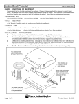
With the insert 12” from the fireplace, install the side surround panels (see the directions below).
Avalon Pendleton-45 and Rainier-45:
Remove the brass trim along the top of the stove.
Attach the side panels with
Side
the included screws (hint:
Panel
pre-thread the holes prior
to installing the panels).
Button Plugs
(pry out with a screwdriver)
5/16" Nutdriver
Travis Industries
Page 1 of 2
Printed 11/4/05
Panel Set, Avalon
2.
Adjust the position of the side panels so they are: 1) flush with the bottom of the insert; 2) both
the same distance back from the front of the insert; 3) perpendicular to the floor (use the top
panel, if necessary, to judge alignment). Tighten the screws that hold the side panels in place.
3.
Place the insert into the fireplace and connect the flue (if using a positive or direct connection).
Install the top panel and trim following the directions below.
Micro (1/16”)
Standard
Screwdriver
5/16" Nutdriver
Spring
Top Trim
Top Trim
Clips
"L" Bracket
Top
Panel
Right Side
Trim
Optional Trim Installation:
Insert one leg of each "L" bracket into the top
and side trim piece. Align the trim to form a
precise corner, then tighten the two set
screws with a small standard screwdriver.
Slide the trim over the panels. Place the
spring clips behind the panels at the locations
shown. This keeps the trim tight against the
panel.
Optional Knock-Out
An optional knock-out is provided on both
Install the top panel so the tabs insert
sides if the power cord is routed behind the
into the joggle clips on the top panel
surround panel.
Insulation Installation (required only for face seal installations)
1.
With the insert drawn 6" from the fireplace, glue the insulation strip included with the insert to the
back of the panels using RTV silicon or stove gasket cement. The insulation should be installed
so it overlaps the fireplace opening to form a seal between the panels and the fireplace face. Let
the silicon or cement dry.
2.
Push the insert into the fireplace, allowing the insulation to form a seal between the panels and
the fireplace. Use a screwdriver to tuck any exposed insulation behind the panels.
Travis Industries
Page 2 of 2
Printed 11/4/05