1
dedicated KVM switch and rackmount screen technology
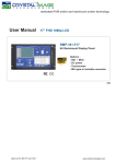
User Manual
Multi-display Control Module Protocol
MCS
Multi-display control solution
751
UM-CV-751-MCS-Q113V1
Contents
< Part. 1 > Interface
1.1
1.2
Connection
Connection Standard
< Part. 2 > Command
2.1
2.2
2.3
CAN Bus Registry
Get Address
Get Name
2.4
2.5
2.6
2.7
2.8
2.9
2.10
2.11
2.12
2.13
2.14
2.15
2.16
2.17
2.18
2.19
2.20
2.21
2.22
2.23
2.24
Get Power Status
Get Display Status
Get Screen Status
Get PIP Status
Get Display ID
Get Display Name
Get Display ID & Name
Volume Control
Mute Control
Input Source Select
OSD Button Control
Infrared Remote Control
Sound Select Control
Contrast Control
Brightness Control
Auto Adjust Control
Power Control
PIP Control
PIP Source Control
PIP Swap Control
PIP Location Control
P.1
P.2 - 3
P.4
P.5
P.6
P.7
P.8
P.9
P.10
P.11
P.12
P.13
P.14
P.15
P.16
P.17
P.18
P.19
P.20
P.21
P.22
P.23
P.24
P.25
P.26 - 27
P.28
P.29
< Part 1 > Interface
< 1.1 > Connection
- As shown in Fig. 1-1, first, connect the personal computer’s RS-232C serial port to the 1st LCD dis
play’s LINK port and then begin to add connections from a LCD display, starting from the OUT port.
- The first & last LCD displays located at both ends of daisy chain connection must be terminated by
setting the pin 1 & 2 of DIP switch ( Set ) to ON position, located next to OUT port. For other daisy
chain LCD display(s), please keep the pin 1 & 2 of DIP switch at OFF position ( Pin 1 & 2 are
default at OFF position ).
*The new DIP switch setting requires a power cycle of LCD display to take effect.
- The MCS module of LCD display will automatically assign an available ID number from 1 to 64 to
each LCD display when connected to the daisy chain, to eliminate LCD displays trying to use the
same IDs simultaneously.
Fig. 1-1 Connecting the PC & LCD Displays
Set switch
For the 1st and last display,
push the set switch upward
RS-232C
For other daisy chain displays,
push the set switch downward
15 feet serial cable
( over 15 feet, extender required )
LINK
OUT
IN
Cat5 / 6 cable
max. 300 meters
OUT
IN
Cat5 / 6 cable
max. 300 meters
OUT
IN
OUT
Cat5 / 6 cable
max. 300 meters
RJ-45 jack
Daisy chain up to 1,000
meters and 64 displays
UM-CV-751-MCS-Q113V1
P.1
up to 64 displays
< 1.2 > Connection Standard
1)
Computer to LCD display connection standard
- Conducts bi-directional communication using serial RS232.
- Use three signal wires of TxD, ( pin 2 ), RxD ( pin 3 ) and GND ( pin 5 ), among the RS232
standard wires, as Fig. 2-1.
- Use DTR ( pin 4 ), RTS ( pin 7 ) for hot-plug detect.
- The distance between the PC computer to LCD display is limited 15m.
2)
LCD display to LCD display connection standard
- Conducts bi-directional communication using CAN bus
- A maximum of 64 LCD display units can be daisy chained to one CAN bus, up to 1,000 meters.
- The distance between LCD Displays is limited 300 meters via Cat 5/ 6 cable.
3)
Command communications
The CAN bus requires the MCS module of LCD display registration by sending command < 0x01 >
to add or remove the LCD display(s) from the CAN bus before command communications. Please
refer to page 6 for more details.
All communications are conducted in the form of hexadecimal number, and the checksum calculation
method as below :
Total =
Command + ID + Val1 + Val2 + Val3 + Val4 + Val5 + Val6;
Checksum =
256 – Total;
* Unsigned character of Checksum, Total=0;
Get Power Status
Header
( e.g. Power ON & ID=1 )
Command
0x4D,
0x43,0x06
0x04
Header
Command
0x4D,
0x43,0x06
0x04
Val 1
ID
0x01
Power
Val 2
0x00
Val 3
0x00
Val 4
0x00
Val 5
0x00
Val 6
0x00
Footer
Checksum
Val 1
Val 2
Val 3
Val 4
Val 5
Val 6
0x01
0x00
0x00
0x00
0x00
0x00
0x0D, 0x0A
Footer
0xFA
0x0D, 0x0A
Here, each set functions according to the commands received and responds with ACK at the same time.
Therefore, the operation of each set should be checked after this process.
UM-CV-751-MCS-Q113V1
P.2
< 1.2 > Connection Standard
4)
The status lights ( LED )
Port
Color
Activity
IN
Green
Solid LED indicates that the MSC board is powered on.
No light indicates the board is powered off.
IN
Orange
Blinking LED indicated that the data is being transmitted through the connection. No
light indicates no data is transmitted
Table 2-1 RS-232 Communication Standards
Bit Rate
9600 bps
Data Bits
8 bits
Parity
None
Stop Bits
1 bit
Flow Control
None
Fig. 2-1 RS-232 pin out DB-9 pin used for Asynchronous Data
UM-CV-751-MCS-Q113V1
P.3
< Part 2 > Command
No.
Type of Command
Command
Range of Value ( Decimal )
Wait ACK (ms)
1
CAN Bus Registry
0x01
--
2,000
2
Get Address
0x02
--
200
3
Get Name
0x03
--
200
4
Get Power Status
0x04
0~1
200
5
Get Display Status
0x05
--
200
6
Get Screen Status
0x06
--
200
7
Get PIP Status
0x07
--
200
8
Set Display ID
0x15
1 ~ 64
200
9
Set Display Name
0x16
--
200
10
Show Display ID & Name
0x17
5 ~ 255
200
11
Volume Control
0x20
0 ~ 100
200
12
Mute Control
0x21
0 ~ 100
200
13
Input Source Select
0x22
--
2,000
14
OSD Button Control
0x23
0~1
200
15
Infrared Remote Control
0x24
0~1
200
16
Sound Select Control
0x25
--
200
17
Contrast Control
0x26
0 ~ 100
200
18
Brightness Control
0x27
0 ~ 100
200
19
Auto Adjust
0x28
0
5,000
20
Power Control
0x45
0~1
7,000
21
PIP Control
0x50
--
200
22
PIP Source Select
0x51
--
200
23
Main-PIP Swap Control
0x52
0
200
24
PIP Locate Control
0x53
--
200
UM-CV-751-MCS-Q113V1
P.4
< 2.1 > Detailed Description of Commands
1) CAN Bus Registry
•
Function
The computer registers the MCS module of LCD display(s) to CAN bus daisy chain connection.
*Registration requires when add or remove the LCD displays from the CAN bus connection.
•
Register MCS Module(s)
Header
0x06, 0x4D,0x43
•
Command
0x01
ID
0x00
Val 1
0x00
Val 2
0x00
Val 3
Val 4
Val 5
Val 6
0x00
0x00
0x00
0x00
Footer
Checksum
0x0D, 0x0A
Ack
Header
Command
0x4D, 0x43,0x06
0x01
ID
Val 1
Val 2
Val 3
Val 4
Val 5
Val 6
MAC1
MAC2
MAC3
MAC4
0x00
0x00
Val 4
Val 5
Val 6
Footer
Checksum
0x0D, 0x0A
MAC1 : The 1st byte of MAC address for the LCD display
MAC2 : The 2nd byte of MAC address for the LCD display
MAC3 : The 3rd byte of MAC address for the LCD display
MAC4 : The 4th byte of MAC address for the LCD display
•
Nak
Header
0x4D, 0x43,0x15
Command
Val 1
ID
0x01
ERR
Val 2
0x00
Val 3
0x00
ERR : Error code that shows the type of error that occurred
0x10
Display controller error
0x11
Serial controller error
0x12
Unsupported Command
0x13
Checksum error
0x14
Bad parameter
0x15
Unknown error
UM-CV-751-MCS-Q113V1
P.5
0x00
0x00
0x00
Footer
Checksum
0x0D, 0x0A
< 2.2 > Get Address
•
Function
The computer shows the 32-bit MAC address of the LCD display
•
Get LCD Display Address
Header
0x06, 0x4D,0x43
•
0x02
Val 1
ID
0x00
Val 2
0x00
Val 3
Val 4
Val 5
Val 6
0x00
0x00
0x00
0x00
Val 3
Val 4
Val 5
Val 6
Footer
Checksum
0x0D, 0x0A
Ack
Header
0x4D, 0x43,0x06
•
Command
Command
0x02
Val 1
ID
Val 2
MAC1
MAC2
MAC3
MAC4
0x00
0x00
Val 1
Val 2
Val 3
Val 4
Val 5
Val 6
ERR
0x00
0x00
0x00
0x00
0x00
Footer
Checksum
0x0D, 0x0A
Nak
Header
Command
0x4D, 0x43,0x15
0x02
UM-CV-751-MCS-Q113V1
ID
P.6
Footer
Checksum
0x0D, 0x0A
< 2.3 > Get Name
•
Function
The computer shows the name of the LCD display
•
Get LCD Display Address
Header
0x06, 0x4D,0x43
•
Command
0x03
Val 1
ID
0x00
Val 2
0x00
Val 3
Val 4
Val 5
Val 6
0x00
0x00
0x00
0x00
Val 3
Val 4
Val 5
Val 6
Footer
Checksum
0x0D, 0x0A
Ack
Header
0x4D, 0x43,0x06
Command
0x03
Val 1
ID
Char1
Val 2
Char2
Char3
Char4
Char5
Char6
Val 5
Val 6
Footer
Checksum
0x0D, 0x0A
Char1 : The 1st character of the name
Char2 : The 2nd character of the name
Char3 : The 3rd character of the name
Char4 : The 4th character of the name
Char5 : The 5th character of the name
Char6 : The 6th character of the name
*The default value of the character of the name is 0xFF
•
Nak
Header
0x4D, 0x43,0x15
Command
0x03
UM-CV-751-MCS-Q113V1
Val 1
ID
ERR
Val 2
0x00
Val 3
0x00
P.7
Val 4
0x00
0x00
0x00
Footer
Checksum
0x0D, 0x0A
< 2.4 > Get Power Status
•
Function
The computer shows the power status of the screen of LCD display
•
Get Power Status
Header
0x06, 0x4D,0x43
•
Command
Val 1
ID
0x04
Val 2
0x00
0x00
Val 3
0x00
Val 4
0x00
Val 5
Val 6
0x00
0x00
Val 5
Val 6
Footer
Checksum
0x0D, 0x0A
Ack
Header
0x4D, 0x43,0x06
Command
Val 1
ID
0x04
Power
Val 2
0x00
Val 3
Val 4
0x00
0x00
0x00
0x00
Val 3
Val 4
Val 5
Val 6
Footer
Checksum
0x0D, 0x0A
Power : The power code for the LCD display
•
0x00
Power OFF
0x01
Power ON
Nak
Header
0x4D, 0x43,0x15
Command
0x04
UM-CV-751-MCS-Q113V1
Val 1
ID
ERR
Val 2
0x00
0x00
P.8
0x00
0x00
0x00
Footer
Checksum
0x0D, 0x0A
< 2.5 > Get Display Status
•
Function
The computer shows the current setting of the LCD display
•
Get LCD Display Address
Header
0x06, 0x4D,0x43
•
Command
0x05
Val 1
ID
0x00
Val 2
0x00
Val 3
Val 4
0x00
0x00
Val 5
0x00
Val 6
0x00
Footer
Checksum
0x0D, 0x0A
Ack
Header
0x4D, 0x43,0x06
Command
0x05
ID
Val 1
Val 2
Val 3
Val 4
Val 5
Val 6
Vol
Mute
Input
OSDB
IR
Sound
Vol :
The volume value of the LCD display ( 1~100 )
Mute :
The mute code for the LCD display
Input :
The input source code for the LCD display
Checksum
Footer
0x0D, 0x0A
OSDB : The OSD button control code for the LCD display
IR :
The infrared remote control code for the LCD display
Sound : The sound select code for the LCD display
•
Nak
Header
0x4D, 0x43,0x15
Command
0x05
UM-CV-751-MCS-Q113V1
Val 1
ID
ERR
Val 2
0x00
Val 3
0x00
P.9
Val 4
0x00
Val 5
0x00
Val 6
0x00
Footer
Checksum
0x0D, 0x0A
< 2.6 > Get Screen Status
•
Function
The computer shows the current screen setting of the LCD display
•
Get Screen Status
Header
0x06, 0x4D,0x43
•
Command
0x06
Val 1
ID
0x00
Val 2
0x00
Val 3
Val 4
Val 5
Val 6
0x00
0x00
0x00
0x00
Val 3
Val 4
Val 5
Val 6
Footer
Checksum
0x0D, 0x0A
Ack
Header
0x4D, 0x43,0x06
Command
0x06
Val 1
ID
Ctrast
Val 2
Bright
0x00
0x00
0x00
0x00
Footer
Checksum
0x0D, 0x0A
Ctrast : The contrast value of the display
Bright : The brightness value of the display
•
Nak
Header
0x4D, 0x43,0x15
Command
0x06
UM-CV-751-MCS-Q113V1
Val 1
ID
ERR
Val 2
0x00
Val 3
0x00
P.10
Val 4
0x00
Val 5
0x00
Val 6
0x00
Footer
Checksum
0x0D, 0x0A
< 2.7 > Get PIP Status
•
Function
The computer shows the PIP setting of the LCD display
The PIP function may or not be available on a particular LCD display depending on the model selected
•
Get PIP Status
Header
0x06, 0x4D,0x43
•
Command
0x07
Val 1
ID
Val 2
0x00
0x00
Val 3
Val 4
Val 5
0x00
0x00
0x00
Val 3
Val 4
Val 5
Val 6
0x00
Footer
Checksum
0x0D, 0x0A
Ack
Header
0x4D, 0x43,0x06
PIP :
Command
0x07
Val 1
ID
PIP
Val 2
P.Sour
P.Loc
0x00
0x00
Val 6
0x00
Footer
Checksum
0x0D, 0x0A
The PIP status value code for the display
P.Sour : The PIP source code for the display
P.Loc :
•
The PIP location code for the display
Nak
Header
0x4D, 0x43,0x15
Command
0x07
UM-CV-751-MCS-Q113V1
Val 1
ID
ERR
Val 2
0x00
Val 3
0x00
P.11
Val 4
0x00
Val 5
0x00
Val 6
0x00
Footer
Checksum
0x0D, 0x0A
< 2.8 > Set Display ID
•
Function
The computer changes the LCD display ID number.
•
Set Display ID number
Header
0x06, 0x4D,0x43
Command
0x15
Val 1
ID
NewID
Val 2
0x00
Val 3
0x00
Val 4
0x00
Val 5
0x00
Val 6
0x00
Footer
Checksum
0x0D, 0x0A
NewID : Changes the LCD display’s ID to New ID number (1~64).
*The new ID number will be treated as bad parameter, if the number is 0, 65 ~ 255 or the
new ID number already occupied by other LCD display.
•
•
Ack
Header
Command
0x4D, 0x43,0x06
0x15
ID
Val 1
Val 2
Val 3
Val 4
Val 5
Val 6
NewID
0x00
0x00
0x00
0x00
0x00
Footer
Checksum
0x0D, 0x0A
Nak
Header
0x4D, 0x43,0x15
Command
0x15
UM-CV-751-MCS-Q113V1
Val 1
ID
ERR
Val 2
0x00
Val 3
0x00
P.12
Val 4
0x00
Val 5
0x00
Val 6
0x00
Footer
Checksum
0x0D, 0x0A
< 2.9 > Set Display Name
•
Function
The computer sets the name of the LCD display.
•
Set Display Name
Header
0x06, 0x4D,0x43
Command
0x16
Val 1
ID
Char1
Val 2
Val 3
Val 4
Val 5
Val 6
Char2 Char3 Char4 Char5 Char6
Footer
Checksum
0x0D, 0x0A
Char1 : The 1st character of the name
Char2 : The 2nd character of the name
Char3 : The 3rd character of the name
Char4 : The 4th character of the name
Char5 : The 5th character of the name
Char6 : The 6th character of the name
*Character of the name can allow [ a~z ],[ A~Z] , [ 0-9 ] & space character.
•
Ack
Header
0x4D, 0x43,0x06
•
Command
0x16
Val 1
ID
Val 2
Val 3
Val 4
Val 5
Val 6
Char1
Char2
Char3
Char4
Char5
Char6
Val 1
Val 2
Val 3
Val 4
Val 5
Val 6
Footer
Checksum
0x0D, 0x0A
Nak
Header
0x4D, 0x43,0x15
Command
0x16
UM-CV-751-MCS-Q113V1
ID
ERR
0x00
0x00
P.13
0x00
0x00
0x00
Footer
Checksum
0x0D, 0x0A
< 2.10 > Show Display ID & Name
•
Function
The LCD Display shows the ID number & name on the screen
•
Show Display ID and Name
Header
0x06, 0x4D,0x43
Command
0x17
Val 1
ID
Time
Val 2
0x00
Val 3
0x00
Val 4
0x00
Val 5
0x00
Val 6
0x00
Footer
Checksum
0x0D, 0x0A
Time : The second value for the screen shows the display ID no. & name ( 5~255 )
•
Ack
Header
0x4D, 0x43,0x06
•
Command
0x17
Val 1
ID
Time
Val 2
0x00
Val 3
0x00
Val 4
0x00
Val 5
0x00
Val 6
0x00
Footer
Checksum
0x0D, 0x0A
Nak
Header
0x4D, 0x43,0x15
Command
0x17
UM-CV-751-MCS-Q113V1
Val 1
ID
ERR
Val 2
0x00
Val 3
0x00
P.14
Val 4
0x00
Val 5
0x00
Val 6
0x00
Footer
Checksum
0x0D, 0x0A
< 2.11 > Volume Control
•
Function
The computer changes the volume level of the LCD display
The audio function may or not be available on a particular LCD display depending on the model selected
•
Set Volume
Header
0x06, 0x4D,0x43
Command
0x20
Val 1
ID
Vol
Val 2
0x00
Val 3
0x00
Val 4
0x00
Val 5
0x00
Val 6
0x00
Footer
Checksum
0x0D, 0x0A
Vol : The volume level value code of the LCD display (0~100)
•
Ack
Header
0x4D, 0x43,0x06
•
Command
0x20
Val 1
ID
Vol
Val 2
0x00
Val 3
0x00
Val 4
0x00
Val 5
0x00
Val 6
0x00
Footer
Checksum
0x0D, 0x0A
Nak
Header
0x4D, 0x43,0x15
Command
0x20
Val 1
ID
ERR
Val 2
0x00
Val 3
0x00
P.15
Val 4
0x00
Val 5
0x00
Val 6
0x00
Footer
Checksum
0x0D, 0x0A
< 2.12 > Mute Control
•
Function
The computer turns the mute ON or OFF of the LCD display
The audio function may or not be available on a particular LCD display depending on the model selected
•
Set Mute Control
Header
0x06, 0x4D,0x43
Command
Val 1
ID
0x21
Mute
Val 2
0x00
Val 3
0x00
Val 4
0x00
Val 5
Val 6
0x00
0x00
Val 5
Val 6
Footer
Checksum
0x0D, 0x0A
Mute : The mute code for the LCD display
•
0x00
Mute OFF
0x01
Mute ON
Ack
Header
0x4D, 0x43,0x06
•
Command
0x21
Val 1
ID
Val 2
Val 3
Val 4
Mute
0x00
0x00
0x00
0x00
0x00
Val 1
Val 2
Val 3
Val 4
Val 5
Val 6
Footer
Checksum
0x0D, 0x0A
Nak
Header
0x4D, 0x43,0x15
Command
0x21
ID
ERR
0x00
0x00
P.16
0x00
0x00
0x00
Footer
Checksum
0x0D, 0x0A
< 2.13 > Input Source Select
•
Function
The computer changes the input source of the LCD display
Some of inputs may or not be available on a particular LCD display depending on the model selected
•
Set Input Source
Header
0x06, 0x4D,0x43
Command
Val 1
ID
0x22
Input
Val 2
0x00
Val 3
0x00
Val 4
0x00
Val 5
Val 6
0x00
0x00
Val 5
Val 6
Footer
Checksum
0x0D, 0x0A
Input : The input source code for the LCD display
•
0x10
VGA
0x11
S-Video
0x12
Composite
0x13
DVI-D
0x14
HDMI
0x15
SDI
0x16
YPbPr
0x17
TV
Ack
Header
0x4D, 0x43,0x06
•
Command
0x22
Val 1
ID
Val 2
Val 3
Val 4
Input
0x00
0x00
0x00
0x00
0x00
Val 1
Val 2
Val 3
Val 4
Val 5
Val 6
Footer
Checksum
0x0D, 0x0A
Nak
Header
0x4D, 0x43,0x15
Command
0x22
ID
ERR
0x00
0x00
P.17
0x00
0x00
0x00
Footer
Checksum
0x0D, 0x0A
< 2.14 > OSD Button Control
•
Function
The computer switches the OSD button function ON /OFF
•
Set OSD Button
Header
0x06, 0x4D,0x43
Command
0x23
Val 1
ID
OSDB
Val 2
0x00
Val 3
0x00
Val 4
0x00
Val 5
0x00
Val 6
0x00
Footer
Checksum
0x0D, 0x0A
OSDB : The OSD membrane button control code for the LCD display
•
0x00
OFF
0x01
ON
Ack
Header
0x4D, 0x43,0x06
•
Command
0x23
Val 1
ID
Val 2
Val 3
Val 4
Val 5
Val 6
OSDB
0x00
0x00
0x00
0x00
0x00
Val 1
Val 2
Val 3
Val 4
Val 5
Val 6
Footer
Checksum
0x0D, 0x0A
Nak
Header
0x4D, 0x43,0x15
Command
0x23
ID
ERR
0x00
0x00
P.18
0x00
0x00
0x00
Footer
Checksum
0x0D, 0x0A
< 2.15 > Infrared Remote Control
•
Function
The computer enables and disables the infrared reception feature of the LCD display
•
Set Infrared Remote
Header
0x06, 0x4D,0x43
Command
0x24
Val 1
ID
IR
Val 2
0x00
Val 3
0x00
Val 4
0x00
Val 5
0x00
Val 6
0x00
Footer
Checksum
0x0D, 0x0A
IR : Reception enable / disable code for the LCD display infrared remote control
•
0x00
Remote Disable
0x01
Remote Enable
Ack
Header
0x4D, 0x43,0x06
•
Command
0x24
Val 1
ID
Val 2
Val 3
Val 4
Val 5
Val 6
IR
0x00
0x00
0x00
0x00
0x00
Val 1
Val 2
Val 3
Val 4
Val 5
Val 6
Footer
Checksum
0x0D, 0x0A
Nak
Header
0x4D, 0x43,0x15
Command
0x24
ID
ERR
0x00
0x00
P.19
0x00
0x00
0x00
Footer
Checksum
0x0D, 0x0A
< 2.16 > Sound Select Control
•
Function
The computer switches the sound setting of the LCD display
The PIP function may or not be available on a particular LCD display depending on the model selected
•
Set Sound
Header
0x06, 0x4D,0x43
Command
0x25
Val 1
ID
S.Sel
Val 2
0x00
Val 3
0x00
Val 4
0x00
Val 5
Val 6
0x00
0x00
Val 5
Val 6
Footer
Checksum
0x0D, 0x0A
S.Sel : The sound select code for the LCD display
•
0x01
Main
0x02
PIP
Ack
Header
0x4D, 0x43,0x06
•
Command
0x25
Val 1
ID
Val 2
Val 3
Val 4
S.Sel
0x00
0x00
0x00
0x00
0x00
Val 1
Val 2
Val 3
Val 4
Val 5
Val 6
Footer
Checksum
0x0D, 0x0A
Nak
Header
0x4D, 0x43,0x15
Command
0x25
ID
ERR
0x00
0x00
P.20
0x00
0x00
0x00
Footer
Checksum
0x0D, 0x0A
< 2.17 > Contrast Control
•
Function
The computer adjusts the contrast of the LCD display
•
Set Contrast
Header
Command
0x06, 0x4D,0x43
0x26
ID
Val 1
Val 2
Val 3
Val 4
Val 5
Val 6
ContV
0x00
0x00
0x00
0x00
0x00
Footer
Checksum
0x0D, 0x0A
ContV : The contrast value code for the LCD display ( 0~ 100 )
•
Ack
Header
0x4D, 0x43,0x06
•
Command
0x26
Val 1
ID
Val 2
Val 3
Val 4
Val 5
Val 6
ContV
0x00
0x00
0x00
0x00
0x00
Val 1
Val 2
Val 3
Val 4
Val 5
Val 6
Footer
Checksum
0x0D, 0x0A
Nak
Header
0x4D, 0x43,0x15
Command
0x26
ID
ERR
0x00
0x00
P.21
0x00
0x00
0x00
Footer
Checksum
0x0D, 0x0A
< 2.18 > Brightness Control
•
Function
The computer adjusts the brightness of the LCD display
•
Set Brightness
Header
0x06, 0x4D,0x43
Command
0x27
Val 1
ID
Bright
Val 2
0x00
Val 3
0x00
Val 4
0x00
Val 5
Val 6
0x00
0x00
Val 5
Val 6
Footer
Checksum
0x0D, 0x0A
Bright : The brightness value code for the LCD display ( 0~ 100 )
•
Ack
Header
0x4D, 0x43,0x06
•
Command
0x27
Val 1
ID
Val 2
Val 3
Val 4
Bright
0x00
0x00
0x00
0x00
0x00
Val 1
Val 2
Val 3
Val 4
Val 5
Val 6
Footer
Checksum
0x0D, 0x0A
Nak
Header
0x4D, 0x43,0x15
Command
0x27
ID
ERR
0x00
0x00
P.22
0x00
0x00
0x00
Footer
Checksum
0x0D, 0x0A
< 2.19 > Auto Adjust Control
•
Function
Auto adjusts the VGA picture position on the screen
Available only when input source is VGA
•
Set Auto Adust
Header
0x06, 0x4D,0x43
Command
0x28
Val 1
ID
A.Adj
Val 2
0x00
Val 3
0x00
Val 4
0x00
Val 5
Val 6
0x00
0x00
Val 5
Val 6
Footer
Checksum
0x0D, 0x0A
A.Adj : The auto adjust code for the LCD display ( 0x00 )
•
Ack
Header
0x4D, 0x43,0x06
•
Command
0x28
Val 1
ID
Val 2
Val 3
Val 4
A.Adj
0x00
0x00
0x00
0x00
0x00
Val 1
Val 2
Val 3
Val 4
Val 5
Val 6
ERR
0x00
0x00
0x00
0x00
0x00
Footer
Checksum
0x0D, 0x0A
Nak
Header
Command
0x4D, 0x43,0x15
0x28
ID
P.23
Footer
Checksum
0x0D, 0x0A
< 2.20 > Power Control
•
Function
The computer switches the power for the screen of LCD display
•
Set Power
Header
0x06, 0x4D,0x43
Command
Val 1
ID
0x45
Power
Val 2
0x00
Val 3
0x00
Val 4
Val 5
Val 6
0x00
0x00
0x00
Val 4
Val 5
Val 6
Footer
Checksum
0x0D, 0x0A
Power : The power code for the screen of LCD display
•
0x00
Power OFF
0x01
Power ON
Ack
Header
0x4D, 0x43,0x06
•
Command
0x45
Val 1
ID
Val 2
Val 3
Power
0x00
0x00
0x00
0x00
0x00
Val 1
Val 2
Val 3
Val 4
Val 5
Val 6
Footer
Checksum
0x0D, 0x0A
Nak
Header
0x4D, 0x43,0x15
Command
0x45
ID
ERR
0x00
0x00
P.24
0x00
0x00
0x00
Footer
Checksum
0x0D, 0x0A
< 2.21 > PIP Control
•
Function
The computer turns the PIP function of the LCD display.
The PIP function may or not be available on a particular LCD display depending on the model selected
•
Set PIP Control
Header
0x06, 0x4D,0x43
Command
Val 1
ID
0x50
PIP
Val 2
0x00
Val 3
0x00
Val 4
0x00
Val 5
Val 6
0x00
0x00
Val 5
Val 6
Footer
Checksum
0x0D, 0x0A
PIP : The PIP function code for the LCD display
•
0x10
PIP OFF
0x11
Small
0x12
Large
0x13
Side by side
Ack
Header
0x4D, 0x43,0x06
•
Command
0x50
Val 1
ID
Val 2
Val 3
Val 4
PIP
0x00
0x00
0x00
0x00
0x00
Val 1
Val 2
Val 3
Val 4
Val 5
Val 6
Footer
Checksum
0x0D, 0x0A
Nak
Header
0x4D, 0x43,0x15
Command
0x50
ID
ERR
0x00
0x00
P.25
0x00
0x00
0x00
Footer
Checksum
0x0D, 0x0A
< 2.22 > PIP Source Control
•
Function
The computer adjusts the PIP source of the LCD display
The PIP function may or not be available on a particular LCD display depending on the model selected
Available only when PIP function is ON
•
Set PIP Source
Header
0x06, 0x4D,0x43
Command
Val 1
ID
0x51
P.Sour
Val 2
0x00
Val 3
0x00
Val 4
Val 5
0x00
0x00
Val 6
0x00
Footer
Checksum
0x0D, 0x0A
P.Sour : The PIP source code for the LCD display
•
•
0x10
VGA
0x11
S-Video
0x12
Composite
0x13
DVI-D
0x14
HDMI
0x15
SDI
0x16
YPbPr
0x17
TV
Ack
Header
Command
0x4D, 0x43,0x06
0x51
ID
Val 1
Val 2
Val 3
Val 4
Val 5
Val 6
P.Sour
0x00
0x00
0x00
0x00
0x00
Val 1
Val 2
Val 3
Val 4
Checksum
Footer
0x0D, 0x0A
Nak
Header
0x4D, 0x43,0x15
Command
0x51
ID
ERR
0x00
0x00
P.26
0x00
Val 5
0x00
Val 6
0x00
Footer
Checksum
0x0D, 0x0A
P.24
< 2.22 > PIP Source Control
**The PIP is operable in the following table:
PIP
VGA
S-Video
Composite
DVI-D
HDMI
SDI
YPbPr
TV
VGA
X
O
O
O
O
O
O
O
S-Video
O
X
X
O
O
O
O
X
Composite
O
X
X
O
O
O
O
X
DVI-D
O
O
O
X
X
O
O
O
HDMI
O
O
O
X
X
O
O
O
SDI
O
O
O
O
O
X
X
O
YPbPr
O
O
O
O
O
X
X
O
TV
O
X
X
O
O
O
O
X
Main
P.25
UM-CV-751-MCS-Q113V1
P.27
www.rackmountsales.com
< 2.23 > PIP Swap Control
•
Function
The computer swaps the main screen with PIP screen
The PIP function may or not be available on a particular LCD display depending on the model selected
Available only when the PIP function is ON
•
Set PIP Swap
Header
0x06, 0x4D,0x43
Command
0x52
Val 1
ID
P.Swp
Val 2
0x00
Val 3
0x00
Val 4
0x00
Val 5
Val 6
0x00
0x00
Val 5
Val 6
Footer
Checksum
0x0D, 0x0A
P.Swp : 0x00 ( always )
•
Ack
Header
0x4D, 0x43,0x06
•
Command
0x52
Val 1
ID
Val 2
Val 3
Val 4
P.Swp
0x00
0x00
0x00
0x00
0x00
Val 1
Val 2
Val 3
Val 4
Val 5
Val 6
ERR
0x00
0x00
0x00
0x00
0x00
Footer
Checksum
0x0D, 0x0A
Nak
Header
Command
0x4D, 0x43,0x15
0x52
ID
P.28
Footer
Checksum
0x0D, 0x0A
< 2.24 > PIP Location Control
•
Function
The computer adjusts the PIP position of the display
The PIP function may or not be available on a particular LCD display depending on the model selected
Available only when the PIP is in small or large size state
•
Set PIP location
Header
0x06, 0x4D,0x43
Command
Val 1
ID
0x53
P.Loc
Val 2
0x00
Val 3
0x00
Val 4
0x00
Val 5
Val 6
0x00
0x00
Val 5
Val 6
Footer
Checksum
0x0D, 0x0A
P.Loc : The PIP location code for the LCD display
•
0x10
Upper Left
0x11
Upper Right
0x12
Lower Left
0x13
Lower Right
Ack
Header
0x4D, 0x43,0x06
•
Command
0x53
Val 1
ID
Val 2
Val 3
Val 4
P.Loc
0x00
0x00
0x00
0x00
0x00
Val 1
Val 2
Val 3
Val 4
Val 5
Val 6
Footer
Checksum
0x0D, 0x0A
Nak
Header
0x4D, 0x43,0x15
Command
0x53
ID
ERR
0x00
0x00
P.29
0x00
0x00
0x00
Footer
Checksum
0x0D, 0x0A
The company reserves the right to modify product specifications without prior notice and assumes no responsibility
for any error which may appear in this publication.
UM-CV-751-MCS-Q113V1
www.rackmountsales.com