1
Kramer Electronics, Ltd.
USER MANUAL
Model:
PL-18
Control Port Expander
Contents
Contents
1
2
2.1
3
4
5
6
7
8
8.1
8.2
8.3
8.4
8.5
8.6
9
9.1
9.2
Introduction
Getting Started
Quick Start
Overview
Your PL-18 Control Port Expander
Connecting the PL-18 Control Port Expander
Operating the PL-18 Control Port Expander
Technical Specifications
PL-18 Commands in Protocol 3000
Operating Commands
Help Commands
Result and Error Codes
Identification Commands
Machine Information Commands
Reset Command
Protocol 3000 Syntax
RS-232/2 Settings
Host Message Format
1
1
2
3
4
5
6
6
7
7
9
9
9
10
10
10
10
10
9.2.1
9.2.2
Simple Command
Command String
10
10
9.3
Device Message Format
11
9.3.1
Device Long Response
11
9.4
9.5
9.6
9.7
9.8
9.9
10
10.1
COMMAND TERMS
Entering Commands
Command Forms
Command Chaining
Maximum String Length
Backward Support
Using the P3K Wizard
Updating the PL-18 Firmware
11
12
12
12
12
12
13
13
10.1.1 Downloading The Firmware
10.1.2 Connecting a PC to the PL-18
10.1.3 Updating the Firmware
13
13
14
10.2
20
Changing the Device Parameters
i
Contents
Figures
Figure 1: PL-18 Control Port Expander
Figure 2: Connecting the PL-18 Control Port Expander
Figure 3: P3K Wizard Screen
Figure 4: Connect Serial/USB
Figure 5: Error Message
Figure 6: Device Selection
Figure 7: Open File Window
Figure 8: Device and File Selected
Figure 9: Warning Window
Figure 10: Load Progress
Figure 11: Completion Message
4
5
14
15
15
16
17
18
18
19
19
Tables
Table 1: PL-18 Control Port Expander Functions
Table 2: PL-18 Control Port Expander Technical Specifications
ii
4
6
KRAMER: SIMPLE CREATIVE TECHNOLOGY
Introduction
1
Introduction
Welcome to Kramer Electronics! Since 1981, Kramer Electronics has been
providing a world of unique, creative, and affordable solutions to the vast
range of problems that confront the video, audio, presentation, and
broadcasting professional on a daily basis. In recent years, we have
redesigned and upgraded most of our line, making the best even better! Our
1,000-plus different models now appear in 11 groups 1 that are clearly
defined by function.
Thank you for purchasing the Kramer TOOLS PL-18 Control Port
Expander, which is ideal for:
• Controlling multimedia rooms, such as classrooms, auditoriums,
conference rooms, and so on
Each package includes the following items:
• The PL-18 Control Port Expander
• Windows®-based Kramer control software and Kramer RC-SV
Configuration software
• Power adapter (5V DC input)
• This user manual 2
2
Getting Started
We recommend that you:
• Unpack the equipment carefully and save the original box and
packaging materials for possible future shipment
• Review the contents of this user manual
• Use Kramer high-performance high-resolution cables 3
1 GROUP 1: Distribution Amplifiers; GROUP 2: Switchers and Matrix Switchers; GROUP 3: Control Systems;
GROUP 4: Format/Standards Converters; GROUP 5: Range Extenders and Repeaters; GROUP 6: Specialty AV Products;
GROUP 7: Scan Converters and Scalers; GROUP 8: Cables and Connectors; GROUP 9: Room Connectivity;
GROUP 10: Accessories and Rack Adapters; GROUP 11: Sierra Products
2 Download up-to-date Kramer user manuals from our Web site at http://www.kramerelectronics.com
3 The complete list of Kramer cables is on our Web site at http://www.kramerelectronics.com
1
Getting Started
2.1
Quick Start
This quick start chart summarizes the basic setup and operation steps.
2
KRAMER: SIMPLE CREATIVE TECHNOLOGY
Overview
3
Overview
The PL-18 is a highly versatile port expander that adds RS-232, IR and
relay ports to an RS-232 controller, especially a Kramer RC device such as
RC-2, RC-2C or RC-62/RC-63. It acts as an all-in-one extended remote
control panel for control of A/V equipment—especially projectors and
associated equipment—in any room (such as classrooms, boardrooms, or
auditoriums).
The PL-18 Control Port Expander features:
• One bi-directional serial port for controlling RS-232 based devices
(for example, projectors) on RS-232/1
• One bi-directional port for receiving control commands from a PC,
touch screen, other serial controller or an RC series device on
RS-232/2
• Four relays for the simplified and centralized control of room
functions (such as lighting, closing blinds, screen settings, and so
on)
• Two IR output ports for IR control
• A USB port for firmware upgrade
To achieve the best performance:
• Use only good quality connection cables 1 to avoid interference,
deterioration in signal quality due to poor matching, and elevated
noise levels (often associated with low quality cables)
• Avoid interference from neighboring electrical appliances that may
adversely influence signal quality and position your Kramer PL-18
away from moisture, excessive sunlight and dust
1 Available from Kramer Electronics on our Web site at http://www.kramerelectronics.com
3
Your PL-18 Control Port Expander
4
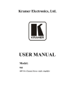
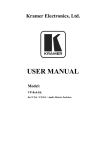
Your PL-18 Control Port Expander
Figure 1 and Table 1 define PL-18.
Figure 1: PL-18 Control Port Expander
Table 1: PL-18 Control Port Expander Functions
#
1
2
3
4
5
6
7
8
9
10
11
4
Feature
ON LED
RS-232 Tx/Rx LEDs
Function
Illuminates green when receiving power
Illuminate red while transmitting and green while receiving data on
an RS-232 port
IR LEDs
Illuminate green when an IR port is active
RELAY LEDs
Illuminate green when an relay is active (from 1 to 4)
PROGRAM USB Connector
Connects to a computer to upgrade firmware
RELAY Terminal Blocks
Connect to relay-driven devices (from 1 to 4)
IR OUTPUT 3.5mm Mini Jacks Connect to IR emitter cables (from 1 to 2)
RS-232/1 Terminal Block
Connects to an RS-232 device that is controlled
RS-232/2 Terminal Block
Connects to an external controller (PC, touch screen or RC device)
PROGRAM Switch
For factory use only. Do not operate during firmware upgrade
5V DC
+5V DC connector for powering the unit
KRAMER: SIMPLE CREATIVE TECHNOLOGY
Connecting the PL-18 Control Port Expander
5
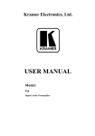
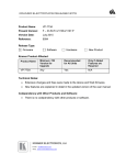
Connecting the PL-18 Control Port Expander
To connect the PL-18, as the example in Figure 2 illustrates, do the
following 1:
1. Connect the RS-232 ports as follows:
Connect RS-232/1 to a projector
Connect RS-232/2 to a PC, touch screen or an RC device
2. Connect the RELAY 2 terminal block connectors as follows:
Connect RELAYS 1 and 2 to window blinds
Connect RELAYS 3 and 4 to a screen
3. Connect the IR OUTPUTS as follows:
Connect IR OUTPUT 1 to a DVD
Connect IR OUTPUT 2 to a display
Figure 2: Connecting the PL-18 Control Port Expander
1 Switch OFF the power on each device before connecting it to your PL-18. After connecting your PL-18, switch on its power
and then switch on the power on each device
2 On each 3-pole terminal block connector, connect either: C to NO, or C to NC (C is common, NO is normally open and NC
is normally closed)
5
Operating the PL-18 Control Port Expander
6
Operating the PL-18 Control Port Expander
The PL-18 is typically used to expand the number of ports available to an
RC series remote control device. The combined RC 1 and PL-18 are
configured from the RC device using RC-SV software that can be
downloaded from the Kramer Web site 2.
The PL-18 can also be operated directly from a PC, touch screen system, or
other serial controller using the serial commands of Kramer’s Protocol
3000. For an explanation of all control commands, see section 9.
In addition to operating the PL-18, machine software can be upgraded, and
device parameters can be accessed and changed using P3K Wizard software
also available from the Kramer Web site2 (see section 10).
7
Technical Specifications
The PL-18 technical specifications are shown in Table 2:
Table 2: PL-18 Control Port Expander Technical Specifications
PORTS:
OUTPUTS:
LED INDICATORS:
POWER SOURCE:
DIMENSIONS
WEIGHT:
ACCESSORIES:
OPTIONS:
3
2 bi-directional RS-232 ports on terminal block connectors; 1 USB
4 relays on terminal block connectors, 36V AC or DC, 1A, 60V AC max on noninductive load; 2 IR outputs on 3.5mm mini jack connector
ON (green), RS-232 (Tx - red and Rx - green), IR (green), relays (green)
5V DC, 260mA
12cm x 7.6cm x 2.4cm (4.72" x 2.97"x 0.96") W, D, H
0.6kg (1.4lbs)
Power supply 5V DC
15 meter and 20 meter IR emitter extension cables
1 When configuring an RC-2 to work with the PL-18, the RC-SV software version must be at 2.1.2.32 or higher and the RC-2
firmware version must be at 1573 or higher
2 At www.kramerelectronics.com
3 Specifications are subject to change without notice
6
KRAMER: SIMPLE CREATIVE TECHNOLOGY
PL-18 Commands in Protocol 3000
8
PL-18 Commands in Protocol 3000
This section describes all commands sent to the PL-18. For an explanation
of the syntax and use of Protocol 3000, see section 9
8.1
Operating Commands
Following are the specific commands that the controller (RC device) sends
to the PL-18 on RS-232/2 to operate the external devices connected to
RS-232/1, the IR ports and relays.
Command
Syntax
Response
Relay control
RELAY PORT_NUM , STATE
RELAY PORT_NUM , STATE
RESULT
Parameter Description:
PORT_NUM = 1 to 4
STATE = Relay state:
‘0’ or ‘close’ to close the relay
‘1’ or ‘open’ to open the relay
Generic Binary Port Configuration Command
CBIN PORT_TYPE,
Config binary port
CBIN PORT_TYPE, PORT_NUM
PORT_NUM[, 1 CFG_VAL1]
[, CFG_VAL1] [, CFG_VAL2]
[, CFG_VAL2][, CFG_VAL3]
[, CFG_VAL3] [, CFG_VAL4]
[, CFG_VAL4][, CFG_VAL5]
[, CFG_VAL5] [, CFG_VAL6]
[, CFG_VAL6][, CFG_VAL7]
[, CFG_VAL7] [, CFG_VAL8]
[, CFG_VAL8]
RESULT
PORT_TYPE = "UART", "ETH", "IR"
PORT_NUM = IR: 1 or 2; UART: 1 (RS-232/1); The port number is written over the physical port (see
Figure 1)
BAUD = 1200, 2400, 4800, 9600, 19200, 38400, 57600, 115200
DATA_BITS = 5 to 8 inclusive
PARITY = “NONE”, “ODD”, “EVEN”, “MARK”, “SPACE” or first letter of those words
STOP_BITS = 1 or 2
DUTY_CYCLE = 1 to 99 inclusive
START_TOKEN = CR followed by “[“ that is, 2 bytes in hex representation = 0x0D and 0x5B
END_TOKEN = “]”
1 CBIN is a generic command, thus CFG_VAL parameters are a generic representation of the specific configuration
parameters, for instance, CFG_VAL1 and CFG_VAL2 represent CARRIER_FREQ and DUTY respectively in case
PORT_TYPE = “IR”
7
PL-18 Commands in Protocol 3000
Explicit Binary Port Configuration Command
UART-CFG PORT_NUM, BAUD,
Config Serial port
(RS-232/1)
DATA_BITS, PARITY, STOP_BITS[,
Config IR out port
DATA_BITS, PARITY, STOP_BITS
FLOW_CONTROL]
[, FLOW_CONTROL] RESULT
IR-CFG PORT_NUM,
IR-CFG PORT_NUM,
CARRIER_FREQ, DUTY_CYCLE
CARRIER_FREQ, DUTY, RESULT
Binary Data Send/Receive
BIN PORT_TYPE, PORT_NUM,
Emit raw data via a
pre-configured binary
RAW_DATA_SIZE START_TOKEN
port
RAW_DATA END_TOKEN
Convey raw data
received through a
preconfigured binary
port
UART-CFG PORT_NUM, BAUD,
BIN PORT_TYPE, PORT_NUM,
RAW_DATA_SIZE [ ] RESULT
1
RBIN PORT_TYPE, PORT_NUM,
RBIN PORT_TYPE, PORT_NUM,
RAW_DATA_SIZE START_TOKEN
RAW_DATA_SIZE [ ] RESULT 2
RAW_DATA END_TOKEN
1
Factory default values of binary ports:
IR1, IR2: Carrier frequency – 38000; duty cycle – 33
RS-232-1: 9600 baud, 8 data bits, parity NONE, 1 stop bit
Configuration and Operation Examples
A binary port must be configured properly before using it to send or receive binary data. The port may be used in
static or dynamic port scenarios:
Static binary port scenario – A specific binary port controls one specific external device (e.g. one RC
button opens a projector; another RC button closes it using the same serial binary port). The port is
configured only once at installation and the value is stored in the non-volatile memory of the PL-18.
Thereafter, when the RC button is pressed it only invokes the configured BIN commands on the PL-18.
Dynamic binary port scenario – A specific binary port controls various external devices (e.g. one RC
button opens a TV, another RC button opens a DVD, and both use the same IR binary port with a dual IR
emitter cable). The binary port must be reconfigured before issuing the BIN command to a different
device. At each RC button press, a CBIN command is sent to the PL-18 before sending a BIN command.
Binary port configuration examples:
Configure UART (RS-232) port 1, with “9600,8,n,1” serial port configuration parameters:
#cbin uart, 1, 9600, 8, n, 1 <CR>
or
#uart-cfg 1, 9600, 8, n, 1 <CR>
Configure IR port 2, with “38000,33” as infrared configuration parameters:
#cbin ir, 2, 38000, 33 <CR>
or
#ir-cfg 2, 38000, 33 <CR>
1 As opposed to any other P3000 command, CR cannot be added after the END_TOKEN
2 The RC responds with this command
8
KRAMER: SIMPLE CREATIVE TECHNOLOGY
PL-18 Commands in Protocol 3000
Using the binary port to send binary data:
Emit via serial port 1 four bytes – the binary representation of P2000 “all-in 2” serial command:
#bin uart, 1, 4 <CR> “[" $01 $82 $80 $81 "]"
Emit via IR port 2 forty-two bytes – the binary representation of Kramer signal “button-1”:
#bin ir, 2, 42 <CR> “[" $FF $01 $8F $69 $67 $65 $66 $69 $66 $6C $63 $66 $C9 $68 $C8 $66 $CB $66 $C8
$CE $FF $01 $BC $69 $66 $66 $C8 $69 $66 $69 $66 $66 $66 $69 $66 $69 $65 $67 $65 $FF $EF $26 "]"
Using the binary port to receive and convey binary data:
Convey four binary bytes received on serial port 1 – these four binary bytes are the binary representation of the
P2000 “all-in 2” serial command:
#rbin uart, 1, 4 <CR> “[" $01 $82 $80 $81 "]"
U
8.2
Help Commands
12B
Command
Syntax
Response
Protocol handshaking
#CR
~OKCRLF
8.3
Result and Error Codes
13B
Result/Error
Syntax
Command ran successfully, no error.
COMMAND PARAMETERS OK
Protocol Errors:
Syntax error
ERR001
Command not available for this device
ERR002
Parameter is out of range
ERR003
Unauthorized access (command run without the matching
login).
ERR004
8.4
Identification Commands
14B
Command
Syntax
Response
Protocol handshaking
#CR
~OK CRLF
Read device model
MODEL?
MODEL MACHINE_MODEL
Read device serial number
SN?
SN SERIAL_NUMBER
Read device firmware
version
VERSION?
VERSION MAJOR .MINOR .BUILD .REVISION
Set machine name
NAME MACHINE_NAME
NAME MACHINE_NAME RESULT
Read machine name
NAME?
NAME MACHINE_NAME
Reset machine name to
factory default*
NAME-RST
NAME-RST MACHINE_FACTORY_NAME
RESULT
Visual identification
IDV
IDV OK
*Note: The machine name is not the same as the model name. The machine name is used to identify a specific
machine or a network in use (with DNS feature on).
MACHINE_NAME = Up to 14 alphameric chars.
* Machine factory name = Model name + last 4 digits from serial number.
9
Protocol 3000 Syntax
8.5
Machine Information Commands
Command
Syntax
Response
Execute firmware upgrade*
UPGRADE
UPGRADE OK
Firmware usually uploads to a device via a command like LDFW. The device may need to be reset to complete
the process.
Reset to factory default
configuration
8.6
FACTORY
FACTORY RESULT
Reset Command
Command
Syntax
Response
Reset device
RESET
RESET OK
9
Protocol 3000 Syntax
Protocol 3000 is used to control the PL-18 via the RS-232/2 connection
using an RC-type controller or a PC, touch screen, other serial controller.
9.1
RS-232/2 Settings
Port
RS-232/2
Baud Rate:
115,200
Data Bits:
8
Stop Bits:
1
Parity:
None
Command Format:
ASCII
9.2
Host Message Format
Start
Address (optional)
Body
Delimiter
#
Destination_id@
Message
CR
9.2.1 Simple Command
Command string with only one command without addressing:
Start
Body
Delimiter
#
Command SP Parameter_1,Parameter_2,…
CR
9.2.2 Command String
Formal syntax with commands concatenation and addressing:
Start
Address
Body
Delimiter
#
Destination_id@
Command_1 Parameter1_1,Parameter1_2,…|
Command_2 Parameter2_1,Parameter2_2,…|
Command_3 Parameter3_1,Parameter3_2,…|…
CR
10
KRAMER: SIMPLE CREATIVE TECHNOLOGY
Protocol 3000 Syntax
9.3
Device Message Format
Start
Address (optional)
Body
delimiter
~
Sender_id@
Message
CR LF
9.3.1 Device Long Response
Echoing command:
Start
Address (optional)
Body
Delimiter
~
Sender_id@
Command SP [Param1 ,Param2 …] result
CR LF
CR = Carriage return (ASCII 13 = 0x0D)
LF = Line feed (ASCII 10 = 0x0A)
SP = Space (ASCII 32 = 0x20)
9.4
COMMAND TERMS
Command
A sequence of ASCII letters ('A'-'Z', 'a'-'z' and '-').
Command and parameters must be separated by at least one space.
Parameters
A sequence of alphameric ASCII characters ('0'-'9','A'-'Z','a'-'z' and some
special characters for specific commands). Parameters are separated by
commas.
Message string
Every command entered as part of a message string begins with a message
starting character and ends with a message closing character.
Note: A string can contain more than one command. Commands are
separated by a pipe ( '|' ) character.
Message starting character
'#' – For host command/query
'~' – For machine response
Device address (Optional, for K-NET)
K-NET Device ID followed by '@'
Query sign
'?' follows some commands to define a query request.
All outputs sign
'*' defines all outputs.
Message closing character
CR – For host messages; carriage return (ASCII 13)
11
Protocol 3000 Syntax
CRLF – For machine messages; carriage return (ASCII 13) + line-feed
(ASCII 10)
Command chain separator character
When a message string contains more than one command, separate each
command with a pipe ( '|' ) character.
Spaces between parameters or command terms are ignored.
9.5
Entering Commands
You can directly enter all commands using a terminal with ASCII
communications software, such as HyperTerminal, Hercules, etc. Connect
the terminal to the serial, Ethernet, or USB port on the Kramer device. To
enter CR , press the Enter key.
( LF is also sent but is ignored by command parser).
For commands sent from some non-Kramer controllers like Crestron, some
characters require special coding (such as, /X##). Refer to the controller
manual.
9.6
Command Forms
Some commands have short name syntax in addition to long name syntax to
allow faster typing. The response is always in long syntax.
9.7
Command Chaining
Multiple commands can be chained in the same string. Each command is
delimited by a pipe character ( '|' ). When chaining commands, enter the
message starting character and the message closing character only once,
at the beginning of the string and at the end.
Commands in the string do not execute until the closing character is
entered.
A separate response is sent for every command in the chain.
9.8
Maximum String Length
64 characters
9.9
Backward Support
Protocol 2000 is transparently supported by Protocol 3000. You can switch
between protocols using a switch protocol command from either platform.
12
KRAMER: SIMPLE CREATIVE TECHNOLOGY
Using the P3K Wizard
10
Using the P3K Wizard
The P3K Wizard is a Kramer software program for:
• Upgrading the machine firmware (see section 10.1)
• Accessing and changing device parameters (see section 10.2).
The P3K Wizard can be downloaded from the Kramer Web site 1.
10.1 Updating the PL-18 Firmware
The PL-18 uses a microcontroller that runs firmware located in FLASH
memory. The latest version of firmware can be downloaded from the
Kramer Web site and updated in minutes using the PK3 Wizard and the
following procedures.
To update the PL-18 firmware:
• Download the firmware file from the Internet (see section 10.1.1)
• Connect a PC directly 2 to the PL-18 (see section 10.1.2)
• Update the firmware using the P3K Wizard (see section 10.1.3)
10.1.1 Downloading The Firmware
To download the latest firmware file 3 from the Internet:
1. Go to the Kramer Web site at www.kramerelectronics.com.
2. Navigate to SUPPORT / Software Firmware Updates.
3. Click on the link of the firmware that applies to your product. Download it
and save it to your disk.
4. Extract the file to a folder (for example, C:\Program Files\Kramer Flash).
10.1.2 Connecting a PC to the PL-18
To connect a PC to the PL-18:
• Connect a serial cable from an RS-232 9-pin D-sub rear panel port
on the PC to the RS-232/2 port of the PL-18 as explained in section
5, or
• Connect a USB cable from a USB port on the PC to the USB port
on the PL-18
1 www.kramerelectronics.com
2 You cannot upgrade the firmware of the PL-18 through an RC connection. The PL-18 must be connected directly to a PC
3 The files indicated in this section are given as an example only. File names are liable to change from time to time
13
Using the P3K Wizard
10.1.3 Updating the Firmware
To update the firmware, perform the following steps:
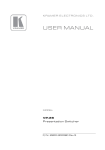
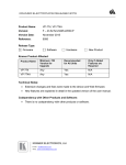
1. Open the Kramer P3K Wizard1 by double-clicking the desktop icon P3K
Wizard.
The P3K Wizard screen appears2:
Figure 3: P3K Wizard Screen
2. Click the Connect button.
The Connect Window appears.
Note: The PL-18 does not have an Ethernet interface. Do not select any of
the Ethernet options on the Connect window.
1 You can download and install the latest version of the P3K Wizard from www.kramerelectronics.com.
2 The screens appearing in this manual are examples of the process. The actual screens may differ in their content.
14
KRAMER: SIMPLE CREATIVE TECHNOLOGY
Using the P3K Wizard
Figure 4: Connect Serial/USB
3. To upgrade using an RS-232 or USB connection, click Serial/USB (see
Figure 4).
Click the drop-down box to show the COM ports
Select a COM port to connect (from COM1 to
COM13) and click OK
Note: If you try to connect to a device and it does not respond, the
following error message appears. Click OK. Verify that the device is
powered on, the cable connection is good, and that you are trying to connect
by the correct method.
Do not operate the PROGRAM switch on the back panel. It is for factory
use only.
Figure 5: Error Message
15
Using the P3K Wizard
4. After pressing OK on the Connect Window, the wizard searches the line for
connected devices. All detected devices are displayed in the device list box
under “Please select the device for update”:
Note: In the Device Properties section, you can update any of the active
fields that have a white background. After making any changes, click Set.
Figure 6: Device Selection
5. In the device list box, click to select the target device.
6. Next, select the firmware file to upgrade by clicking Browse next to the
Firmware file box.
The Open File window opens:
16
KRAMER: SIMPLE CREATIVE TECHNOLOGY
Using the P3K Wizard
Figure 7: Open File Window
7. Navigate to the folder containing the firmware file (for example,
C:\Program Files\Kramer Flash).
8. Select the firmware file you downloaded in section 10.1.1 and click Open.
The firmware file appears in the Firmware file box.
17
Using the P3K Wizard
Figure 8: Device and File Selected
9. Click the Start Upgrade button to begin the file transfer.
The Warning window appears:
Figure 9: Warning Window
10. Click Yes to continue.
Load Progress appears in the bottom box:
18
KRAMER: SIMPLE CREATIVE TECHNOLOGY
Using the P3K Wizard
Figure 10: Load Progress
11. When the upload is finished, the completion message appears:
Figure 11: Completion Message
12. Click Close to close the P3K Wizard and remove the cable that connects the
PL-18 to the PC.
19
Using the P3K Wizard
10.2 Changing the Device Parameters
To change the device parameters, (for example, the K-NET ID) do the
following:
1. Connect a PC to the PL-18 (see section 10.1.2).
2.
Open the Kramer P3K Wizard1 by double-clicking the desktop icon P3K
Wizard.
The P3K Wizard screen appears (see Figure 3).
3.
Click the Connect button to open the Connect window (see Figure 4).
4.
Choose the SERIAL/USB connection, and click OK.
The Connect window disappears and the Device Properties become visible.
5.
Change the parameters as required and click SET.
1 You can download and install the latest version of the P3K Wizard from www.kramerelectronics.com
20
KRAMER: SIMPLE CREATIVE TECHNOLOGY
LIMITED WARRANTY
Kramer Electronics (hereafter Kramer) warrants this product free from defects in material and workmanship under the
following terms.
HOW LONG IS THE WARRANTY
Labor and parts are warranted for seven years from the date of the first customer purchase.
WHO IS PROTECTED?
Only the first purchase customer may enforce this warranty.
WHAT IS COVERED AND WHAT IS NOT COVERED
Except as below, this warranty covers all defects in material or workmanship in this product. The following are not covered
by the warranty:
1. Any product which is not distributed by Kramer, or which is not purchased from an authorized Kramer dealer. If you are
uncertain as to whether a dealer is authorized, please contact Kramer at one of the agents listed in the Web site
www.kramerelectronics.com.
2. Any product, on which the serial number has been defaced, modified or removed, or on which the WARRANTY VOID
IF TAMPERED sticker has been torn, reattached, removed or otherwise interfered with.
3. Damage, deterioration or malfunction resulting from:
i) Accident, misuse, abuse, neglect, fire, water, lightning or other acts of nature
ii) Product modification, or failure to follow instructions supplied with the product
iii) Repair or attempted repair by anyone not authorized by Kramer
iv) Any shipment of the product (claims must be presented to the carrier)
v) Removal or installation of the product
vi) Any other cause, which does not relate to a product defect
vii) Cartons, equipment enclosures, cables or accessories used in conjunction with the product
WHAT WE WILL PAY FOR AND WHAT WE WILL NOT PAY FOR
We will pay labor and material expenses for covered items. We will not pay for the following:
1. Removal or installations charges.
2. Costs of initial technical adjustments (set-up), including adjustment of user controls or programming. These costs are the
responsibility of the Kramer dealer from whom the product was purchased.
3. Shipping charges.
HOW YOU CAN GET WARRANTY SERVICE
1. To obtain service on you product, you must take or ship it prepaid to any authorized Kramer service center.
2. Whenever warranty service is required, the original dated invoice (or a copy) must be presented as proof of warranty
coverage, and should be included in any shipment of the product. Please also include in any mailing a contact name,
company, address, and a description of the problem(s).
3. For the name of the nearest Kramer authorized service center, consult your authorized dealer.
LIMITATION OF IMPLIED WARRANTIES
All implied warranties, including warranties of merchantability and fitness for a particular purpose, are limited in duration to
the length of this warranty.
EXCLUSION OF DAMAGES
The liability of Kramer for any effective products is limited to the repair or replacement of the product at our option. Kramer shall
not be liable for:
1. Damage to other property caused by defects in this product, damages based upon inconvenience, loss of use of the product, loss
of time, commercial loss; or:
2. Any other damages, whether incidental, consequential or otherwise. Some countries may not allow limitations on how long an
implied warranty lasts and/or do not allow the exclusion or limitation of incidental or consequential damages, so the above
limitations and exclusions may not apply to you.
This warranty gives you specific legal rights, and you may also have other rights, which vary from place to place.
NOTE: All products returned to Kramer for service must have prior approval. This may be obtained from your dealer.
This equipment has been tested to determine compliance with the requirements of:
EN-50081:
EN-50082:
CFR-47:
"Electromagnetic compatibility (EMC);
generic emission standard.
Part 1: Residential, commercial and light industry"
"Electromagnetic compatibility (EMC) generic immunity standard.
Part 1: Residential, commercial and light industry environment".
FCC* Rules and Regulations:
Part 15: “Radio frequency devices
Subpart B Unintentional radiators”
CAUTION!
Servicing the machines can only be done by an authorized Kramer technician. Any user who makes changes or
modifications to the unit without the expressed approval of the manufacturer will void user authority to operate the
equipment.
Use the supplied DC power supply to feed power to the machine.
Please use recommended interconnection cables to connect the machine to other components.
* FCC and CE approved using STP cable (for twisted pair products)
21
For the latest information on our products and a list of Kramer
distributors, visit our Web site: www.kramerelectronics.com
where updates to this user manual may be found.
We welcome your questions, comments and feedback.
Safety Warning:
Disconnect the unit from the power supply before
opening/servicing.
Caution
Kramer Electronics, Ltd.
Web site: www.kramerelectronics.com
E-mail: [email protected]
P/N: 2900-000505 REV 3