1
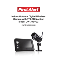
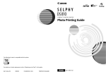
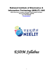
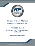
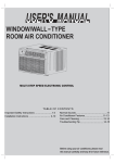
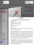
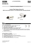
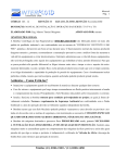
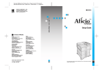
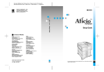
3x PTZ Series
P3D-E48
P3ID17-E48
3x Pan/Tilt/Zoom Indoor Mini Dome Camera
PT Series
PD-E5343
PID17-E5343
Pan/Tilt Indoor Mini Dome Camera w/ 4.3mm Lens
3x Pan/Tilt/Zoom Indoor Mini Dome Camera w/ 17 IR
Pan/Tilt Indoor Mini Dome Camera w/ 4.3mm Lens w/ 17 IR
Also Available for 6.0mm Lens , PD-E5360 & PID17-E5360
OPERATIONAL MANUAL
INDOOR MINI DOME CAMERA
3x PTZ
PT Only
P3D-E48
P3ID17-E48
Copyright
© 2009.
All Rights Reserved.
PAL Version
Also Available http://www.okinausa.com
PD-E5343
PID17-E5343
Please read the Operational Manual
before attempting to use this product.
1
REV081709
FEATURES
P3D-E48 & P3ID17-E48
• 1/4” Sony Super HAD CCD
• 480 TV Lines
• 17 IR LED – P3ID17
• IR Distance up to 30ft – P3ID17
• Pentax 3x Optical Zoom Lens
f=2.8mm~7.3mm
• Pan Speed: 8°~80° per sec
• Tilt Speed: 8°~80° per sec
• Pan Angle 0°~355°, Tilt Angle: 0°~90°
• 32 Preset Points
• 1.0 Lux @ F2.0
• Protocols Selected by DIP Switch
• RS485 Interface
• 0~255 ID Address
• 12V DC, 1000mA
PD-E5343 & PID17-E5343
• 1/3” Sony Super HAD CCD
• 530 TV Lines
• 17 IR LED – PID17
• IR Distance up to 30ft – PID17
• 4.3mm Fixed IR Lens*
Also Available for 6.0mm Lens
•
•
•
•
•
•
•
•
•
Pan Speed: 8°~80° per sec
Tilt Speed: 8°~80° per sec
Pan Angle 0°~355°, Tilt Angle: 0°~90°
32 Preset Points
0.8 Lux @ F2.0
Protocols Selected by DIP Switch
RS485 Interface
0~255 ID Address
12V DC, 1000mA
*IR Lens = IR Corrected Type Lens
PACKAGE CONTENTS
•
•
•
•
One
One
One
One
(1)
(1)
(1)
(1)
P3D-E48 / P3ID17-E48 / PD-E5343 or PID17-E5343 Camera
Quick Installation Plate
Signal-Power Cable
Operational Manual
* For any returns, please include all components listed above with
original packaging in Resalable Condition. Absolutely No
Returns will be accepted if any component is missing/damaged.
Quick Installation Plate
Signal-Power Cable
INSTALLATION
Step 1:
Setting of Camera Position Code
Prior to installation, setup ID address and communication protocol of your camera first, then you can install it (refer to
page 5 for more details). If resetting of ID or protocol is necessary after installation, please POWER-OFF the camera
before resetting. The new setting will become valid after power is reapplied to the camera.
Step 2:
On the Signal-Power cable, different wires have been labeled with its function: one for Video Output, one for RS485
input and one for 12V DC power input. Please follow these labeling for your correct wiring. There are two installation
methods which you can choose from.
Method 1:
Decide the location where you want to install and then drill one hole with about 2 cm in diameter. Insert
Signal-Power cable through this hole as below:
Copyright © 2009. All Rights Reserved.
http://www.okinausa.com
2
REV081709
Then take out the quick-installation plate which is provided inside the accessory bag. Again insert the SignalPower cable through any round holes of the quick-installation plate and screw it into the platform as shown in
photo A below. Connect the Signal-Power cable to the camera. Twist the base of the dome camera into the
quick-installation plate as shown in photo B. Refer to photo C for completed installation.
(photo A)
(photo B)
(photo C)
Method 2:
Take out the quick-installation plate which is provided from the accessory bag. Screw the quick-installation
plate into the location where you want to install, as shown below:
Connect the Signal-Power cable into the base of the camera as shown in photo A. There are two wiring
direction choices which you can choose from, as shown in photo B and photo C.
(photo A)
(photo B)
(photo C)
Twist the base of the camera into the quick-installation plate, and the installation is done.
*Make sure the camera is locked on
securely to prevent any risk of the camera
falling.
Copyright © 2009. All Rights Reserved.
http://www.okinausa.com
3
REV081709
Step 3:
Power On Test
a. Before connecting the power, make a final check to confirm that the wiring is correct.
b. Before installing this camera, please execute camera self-testing as following: when powering on the camera,
it will automatically execute tilt up/down scanning, then pan horizontal scanning for around 20~30 seconds,
then camera will stop at the Preset Point 1. Upon completion of these, the speed dome camera is in normal
condition.
NOTE: This product is normally installed in an elevated position. Installation work should comply with local safe
regulations. Proper safety precautions and protective measures shall be taken for installing the camera. For the
personnel safety’s sake, carry out power on and product test only after completion of installation work.
USING IR REMOTE CONTROL
This camera has built-in IR Receiver, which will allow user to use our IR Remote Controller (Model: PTZ-IR10, optional
device) to control the movement of Mini Speed Dome Camera. (The operation of such IR Remote Controller can be
found on the user’s manual of PTZ-IR10)
RS485 WIRING METHOD
Two RS485 wiring methods can be used according to actual needs. We recommend the following wiring methods to
avoid malfunction of RS485 control.
1. RS485 serial connection:
This method connects the dome cameras in sequential manner where the first camera connects to the second and
then the second to the third, and so on until the last one is connected. A terminal resistance is connected to the
last camera to form a closed loop. See the following illustration:
PELCO
Control Keyboard
When using RS485 serial connection, the max. in one serial connection is to connect up to 32 pieces of speed
dome. If over 32 pieces of speed dome, please use “RS485 Aster Connection” method together with our DS810 (8
port RS485 distributor) to diversify the number of speed domes in one single serial connection in order to make
sure the stability of the complete control system.
2. RS485 Aster Connection:
This is the most common method in practical installation work. In the aster connection, if an RS485 distributor is
not utilized, it is likely to have reflected signal and to lower the ability of resisting interference. This may cause
malfunctioning of the control signal that results in faulty control of the camera or unstopping operation when the
control signal is stopped.
Copyright © 2009. All Rights Reserved.
http://www.okinausa.com
4
REV081709
In such cases, we recommend to use our DS810 RS485 Distributor. This product can effectively convert the aster
connection into the correct connection method that meets RS485 requirements to acquire optimal communication
reliability. See the following diagram for reference.
PELCO
Control Keyboard
COMMUNICATION PROTOCOL & ID ADDRESS SETTING
NOTE: Please POWER-OFF the camera before resetting. The new setting will become valid after power is reapplied to
the camera.
Open the plastic cover (as shown below) on the back-side of the camera.
You will find one 10-PIN DIP SWITCH. SW9/10 is for setting the
camera’s protocols.
1. Setting for Communication Protocol
Copyright © 2009. All Rights Reserved.
http://www.okinausa.com
5
OKINA USA
PELCO P-9600
PELCO P-4800
PELCO D-2400
DIP 9
ON
OFF
ON
OFF
DIP 10
ON
ON
OFF
OFF
REV081709
2. Setting the ID address of the camera is shown below:
Please change DIP SWITCH SW1~8 as below:
1 2 3 4 5 6 7 8
1 2 3 4 5 6 7 8
26
27
28
29
30
31
32
33
34
35
36
37
38
39
40
41
42
43
44
45
46
47
48
49
50
1
2
3
4
5
6
7
8
9
10
11
12
13
14
15
16
17
18
19
20
21
22
23
24
25
Copyright © 2009. All Rights Reserved.
http://www.okinausa.com
6
REV081709
1 2 3 4 5 6 7 8
1 2 3 4 5 6 7 8
76
77
78
79
80
81
82
83
84
85
86
87
88
89
90
91
92
93
94
95
96
97
98
99
100
51
52
53
54
55
56
57
58
59
60
61
62
63
64
65
66
67
68
69
70
71
72
73
74
75
Copyright © 2009. All Rights Reserved.
http://www.okinausa.com
7
REV081709
1 2 3 4 5 6 7 8
1 2 3 4 5 6 7 8
101
102
103
104
105
106
107
108
109
110
111
112
113
114
115
116
117
118
119
120
121
122
123
124
125
Copyright © 2009. All Rights Reserved.
http://www.okinausa.com
126
127
128
129
130
131
132
133
134
135
136
137
138
139
140
141
142
143
144
145
146
147
148
149
150
8
REV081709
1 2 3 4 5 6 7 8
1 2 3 4 5 6 7 8
151
152
153
154
155
156
157
158
159
160
161
162
163
164
165
166
167
168
169
170
171
172
173
174
175
Copyright © 2009. All Rights Reserved.
http://www.okinausa.com
176
177
178
179
180
181
182
183
184
185
186
187
188
189
190
191
192
193
194
195
196
197
198
199
200
9
REV081709
1 2 3 4 5 6 7 8
1 2 3 4 5 6 7 8
226
227
228
229
230
231
232
233
234
235
236
237
238
239
240
241
242
243
244
245
246
247
248
249
250
201
202
203
204
205
206
207
208
209
210
211
212
213
214
215
216
217
218
219
220
221
222
223
224
225
Copyright © 2009. All Rights Reserved.
http://www.okinausa.com
10
REV081709
1 2 3 4 5 6 7 8
251
252
253
254
255
RS485 COMMON TROUBLESHOOTING
Error
Possible Causes
Solutions
Able to do self-test on 1. Keyboard’s (or DVR’s)
initial power on, but is
communication protocol is not
unable to be controlled
consistent with camera’s
A. Keyboard’s (or DVR’s) baud
rate is not consistent with
camera’s
B. RS485 polarity error
C. RS485 bad wire connection
Control of camera is
working, but not
smoothly
Cannot power on
Copyright © 2009. All Rights Reserved.
http://www.okinausa.com
Alter protocols for consistency
Alter baud rates for consistency
Switch polarity of RS485 pins
Re-check RS485 wiring
1. Keyboard/DVR is too far from
cameras
2. RS485 has a disconnected wire
Check wires for error. Or set terminal
resistance at the last camera.
Reconnect RS485 cable
3. Too many cameras are paralleled
Install an RS485 distributor
1. Contact of 12V DC power is not
good.
1. Check the connection of 12V DC
2. the Voltage of 12V DC adapter is
too low.
2. Check whether the voltage of
power input to speed dome is 12V
DC, if not, please use the adapter
which is more than 12V DC voltage
(but no more than 16V DC,
otherwise it will burn the camera)
11
REV081709
*Terms used for button functions may vary depending on the manufacturer of the controller
OPERATION SETUP INFO
1. Select to Control the Speed Dome Camera:
Enter: CAM + NNN + ENTER
Display: CAMERA ID : NNN
NNN: Users may enter one number from Number 0 ~255 as the number of the speed dome cameras. The
speed dome camera you select to control appears on the LCD screen after one number is entered.
2. Set up the Speed Dome Preset Points:
A. Enter: SET + NN + ENTER
B. Display: SET NO : NNN
C. NNN: Users may enter one number from Number 1 ~ 32 as preset points number.
D. Operation: Move the speed dome to the location you want to set up and set the preset point based on
the method used for Point A. The operation method applies to other preset points setting.
Call the Speed Dome Preset Points:
Enter: PRESET + NN + ENTER
Display: PRESET NO : NN
NN: Preset points, No. 1~32
3. Delete the Speed Dome Preset Points:
Description: This function is designed to clear the preset points by following the operation procedure:
Enter: PRESET + NN + OFF
Display: PRESET NO : NN
NN: Preset points to be deleted, No. 1~32
4. Set up Preset Point Group: (Do not apply to PELCO Protocol)
Description: This function is designed to scan the preset points in order. Each group is allowed to set up 16 preset
points for the moving speed and retention time.
Enter: SHOT + N + ON
If you choose OKINA USA Protocol for one of our speed dome cameras, you may set up 4 preset point groups by
following the operation procedure:
A. Press [ SHOT ] :
LCD displays: SHOT NO : 000
Enter the preset point groups, No. 1 and press the ON key.
LCD displays: Track: 1 Sum: 0
B. Press [ TELE ] :
LCD displays: [ NO: 1 POINT: 0 ]
Enter one of the preset points of the group ranging from No. 1-32.
C. Press [ TELE ] : Set up the moving speed
LCD displays: [ No: 1 Speed: 0 ]
The speed represents the moving speed between two preset points and is divided into 1-8 phase. (1: fastest
speed; 8: slowest speed)
D. Press [ TELE ] : Set up the retention time
LCD displays: [ No: 1 Time: 0 ]
The displayed time is the retention time of each preset point and can be set from 1 to 99 seconds.
E. Press the [ TELE ] key to go back to step B to set up next point. Press [ OFF ] to end and save your setting.
5. Start Preset Point Group Scanning: (Do not apply to PELCO Protocol)
Enter: [SHOT] N [ENTER]
LCD displays: SHOT NO : XXX
XXX: No. 1 preset points group scanning. Complete the preset point setup described in Step 4. before starting
preset point group scanning.
Copyright © 2009. All Rights Reserved.
http://www.okinausa.com
12
REV081709
6. Horizontal Revolution of 2 Preset Points (Do not apply to PELCO Protocol)
Description: This function is designed to set the speed dome at horizontal revolution in a small zone.
Enter: Press [AUTO].
LCD displays: 1ST N0:
Enter a start point for Auto Pan scanning. The start point should be one of the preset points. Complete preset
point setting first by following Step 2.
Press the [ON] key to complete the start point setting.
LCD displays: 2ND NO :
Enter a stop point for Auto Pan scanning. The stop point should be one of the preset points. Complete preset
point setting first by following Step 2.
Press the [OFF] key to complete the stop point setting. The speed dome will begin to move at horizontal
revolution immediately.
PS: If the start point and the stop point are set at the same preset point, the speed dome will move at 360°
horizontal revolution. The start point and the stop point should be selected from one of the 1-32 preset points.
7. Home Position Auto Returning (NEW)
Description: This function is designed to set the speed dome to auto return to Preset point 1 (required) as Home
Position at every 5 minute.
To activate:
Enter: PRESET + 85 + ENTER
To deactivate:
Enter: SET + 85 + ENTER
8. Extended Command
N
Value
No.
92
93
Keyboard Operation Definition
Control Object
[SET]+N+[ENTER]
[PRESET]+N+[ENTER]
START point
PAN SCAN SETTING
STOP point
97
Preset Tour(preset 1~16 point)
OFF
ON
99
Auto PAN Scan
OFF
ON
Copyright © 2009. All Rights Reserved.
http://www.okinausa.com
13
REV081709
SPECIFICATION
3x PTZ
Model
CCD Sensor
Picture Pixels
Resolution
Minimum
Illumination
PT Fixed Lens
P3D-E48
P3ID17-E48
PD-E5343
PID17-E5343
1/4” Sony Super HAD CCD
1/3” Sony Super HAD CCD
NTSC: 410,000 pixels / PAL: 470,000 pixels
480 TV Lines
530 TV Lines
Lens
IR LED
IR Distance
Video Output
Synchronization
Scanning System
S/N Ratio
Electronic
Shutter
Back Light
White Balance
Pan Scan/Angle
Tilt Scan/Angle
Manual Pan Scan
Speed
Manual Tilt Scan
Speed
Pan Scan Speed
for Preset
Tilt Scan Speed
for Preset
Preset Points
Communication
ID Address
Power Supply
Operation
Temperature
Humidity
1.0 Lux @ F2.0
0.8 Lux @ F2.0
Pentax 3x Optical
4.3mm Fixed IR Lens*
Zoom Lens
Also Available for 6.0mm Lens
f=2.8mm~7.3mm
N/A
17 IR LED
N/A
17 IR LED
N/A
30ft / 10m
N/A
30ft / 10m
1.0Vp-p, 75 Ohm, BNC Connector
Internal
2:1 Interlace Scanning
More than 48dB
Auto / NTSC: 1/60x~1/100,000s / PAL: 1/50x~1/110,000s
Auto
Auto / 2500°K ~ 9500°K
0° ~ 355°
0° ~ 90°
8°~80° per sec vari-speed
8°~80° per sec vari-speed
80° per sec vari-speed
80° per sec vari-speed
32 Preset Points
RS485 Interface
0~255 addresses
12V DC, 1000mA
14°F ~ 122°F / -10°C ~ 50°C
0~95% RH
PAL Version Also Available
*Specifications are subject to change without notice
*IR Lens = IR Corrected Type Lens
PTZ = Pan / Tilt / Zoom
PT = Pan / Tilt
SAFETY PRECAUTIONS
1.
2.
3.
4.
Select a proper location and use safe hoist for installing speed dome cameras.
Confirm that the hoist is capable of lifting to the installation position.
Proper protective measures must be provided in the hoist, for protecting engineering staffs.
Confirm that power supply is 110V/220V. Ensure safety precautions for preventing electric shock.
Copyright © 2009. All Rights Reserved.
http://www.okinausa.com
14
REV081709
PRECAUTIONS ON INSTALLATION
1. Basic requirements for installation
Follow local regulations about installation safety request.
Check out if accessories are complete. Optional accessories are required for different installation sites. Please
contact your local distributors for proper installation accessories, so that the camera could be installed safely
without causing danger.
Check if the installation location is of sufficient height.
Check if the installation location is strong enough for supporting cameras. Make sure installation spots (ceiling or
wall) is of sufficient strength to support the camera and bracket without immediate danger of falling.
2. Cable standards
Coaxial cable for image signal:
Select proper cable length for your installation distance. Recommended spec. is as follows:
a. RG59/U:
750ft (230 meters)
b. RG61/U:
1000ft (305 meters)
c. RG11/U:
1500ft (457 meters)
3. RS485 Cable
Please comply with RS485 wiring standards and select proper RS485 cable. Improper cable may result in RS485
communication transmission error, which may cause speed dome cameras to react incorrectly. Please pay much
attention to this prior to installation.
When thinner or lower anti-interference RS485 cable is used for connecting the camera, the maximum
transmission distance may be shortened and vice versa.
Standard rule for RS485 transmission distance:
When using 20AWG (Belden 8760) Shielded Twisted Pair Cable, different control Baud Rate will have different
transmission distance performance, see table:
Baud rate
Max. Transmission Distance
2400
1200 meters
4800
1000 meters
9600
800 meters
4. Remove protection materials before supplying power to the camera, so as to prevent it from faulty operation or
causing mechanical errors.
IMPORTANT NOTE
1. Never point the camera toward the sun
Do not expose the lens directly to the sun or to strong light as this may damage the pick-up device.
2. Handle this camera with care
Avoid any shock or bumping of the camera. Improper handling could damage the camera.
3. Requires a proper operating environment
This camera is designed for outdoor or indoor use. The allowable temperature range for operation of this camera
is between 14°F ~ 122°F / -10°C ~ 50°C.
4. Clean the front face to the pick-up device
It is recommended that the pick-up device surface be cleaned before lens installation or whenever the lens is
changed. Cleaning should be done by using a chamois, a very fine soft cloth, lens tissue, or cotton tipped
applicator and ethanol to carefully remove any fingerprint or dust.
Copyright © 2009. All Rights Reserved.
http://www.okinausa.com
15
REV081709
5. Check the power source voltage
The power source voltage should be within the specified range. (Camera must meet the specifications). Camera
must be connected to a surge protector at all times. For the safety of the engineering staffs, apply power only
upon completion of installation.
6. Objects and liquid entry
Never push objects of any kind into this camera as this may touch dangerous voltage points of short out parts that
could result in a fire or electric shock. Never spill any kind of liquid on the video product.
7. Servicing
Do not attempt to service this video product by yourself as opening or removing covers may expose you to
dangerous voltage or other hazards. Refer all service to qualified servicing personnel.
8. Damage requiring service
Unplug this video product from the wall outlet and refer service to qualified servicing personnel under the
following conditions:
a. When the power supply cord or plug is damaged.
b. If liquid has been spilled, or objects have fallen into the video product.
c. If the video product has been dropped or the cabinet has been damaged.
d. When the video product exhibits a distinct change in performance.
WARRANTY
OKINA USA products are covered under warranty for one year from the date of purchase. The warranty will
automatically be voided if any of the following occurs:
1. Camera sticker is removed
If the camera sticker is removed, we will not be able to confirm any information regarding when and where the
product was purchased. We have no other way to verify the purchase record without the serial number on the
camera sticker; therefore, it should not be removed.
2. Camera is modified in any way
If the camera is scratched, damaged, or modified in a manner not described in this manual, the warranty will be
voided immediately. It is the customer’s responsibility to keep the camera in good condition.
OPTIONAL ACCESSORIES
Wall Mount Bracket
MB-E5D
Copyright © 2009. All Rights Reserved.
http://www.okinausa.com
Network IP Base Server
NIPD-EB
Keyboard Controller
PTZ-KB10
16
IR Remote Controller
PTZ-IR10
REV081709