1
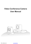
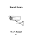
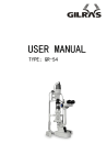
GOLDEN STATE
INSTRUMENT CO.
GS-PTZ-2210
GS-PTZ-1010
Outdoor PTZ Color
Dome Camera
User’s Manual
Please read this manual carefully before operating the high speed integrated video camera.
LIST
Precautions……………………………………………………………2
1.0 Installation…………………………………………………………4
1.1 Indoor type…………………………………………………………4
1.2 Indoor ceiling installation…………………………………………4
1.3 Indoor boom installation……………………………………………5
1.4 Indoor wall installation……………………………………………6
1.5 Indoor embedded installation………………………………………6
1.6 Accessories for indoor installation…………………………………7
2.0 Outdoor type…………………………………………………………8
2.1 Outdoor installation…………………………………………………8
2.2 Accessories of the outdoor installation………………………………12
3.0 Operation mode………………………………………………………14
3.1 Technical parameter…………………………………………………14
3.2 Connection method………………………………………………16
3.3 Address code setting………………………………………………17
3.4 Protocol code setting………………………………………………19
3.5 Indication light description…………………………………………20
4.0 Normal function……………………………………………………20
4.1 Description of icons of the video camera…………………………26
4.2 Solution of common failures………………………………………27
4.3 Connection style of RS-485 bus……………………………………28
5.0 Selection of code dialing switch……………………………………29
1
Precautions
1.
Never disassemble the video camera without authorization.
Never disassemble the screws or protection cover to avoid electrical
shock.. No part inside the machine can be repaired by the users
themselves.
Related maintenance and repair work shall be carried out by qualified
maintenance persons.
2.
Use your video camera carefully.
Never use the video camera at random. Protect the camera from being
impacted and vibration. The video camera may be damaged if it is used
or stored in an improper way.
3.
Never let the video camera get wet in the rain or be used in moist
place.
The indoor spherical video camera is designed for indoor use, so set it in
a place not under rain or moist. It should be maintained by the qualified
maintenance person after cutting off the power. Moisture may damage
the camera and cause electric shock.
4.
Never use strong cleanser with polishing property when cleaning the
camera body.
Wipe the camera with dry and soft cloth when it gets dirt. If the dirt is
serious, slightly wipe it off with neutral cleanser. While wiping, be
careful not to scratch the round protection housing. Then, wipe out the
remainder of the cleanser with dry cloth.
5.
Never aim at the sun with the video camera
Never aim at the bright object with the video camera. The video camera
should not be aimed at the sun or other very bright objects not matter
whether it is in use or not. Otherwise, the image may be faint or have
halation.
6.
Never aim the camera at strong light or expose under the light
source for a long time.
2
If the spot light source such as shooting light forms a facula on the
display screen, the CCD color filter of the camera may be fading.
7.
Don't install the video camera upside down.
This video camera is designed to be installed on the ceiling or wall. If
installing the camera upside down, e. g., on the floor, the camera may
fail.
8.
Never use the video camera in conditions exceeding the temperature
and humidity limit or the power supply specification.
Never use this device in the extreme environment of high temperature
and humidity. Never put it near the radiator, stove or other equipments
that generate heat.
9.
Don't install the video camera near the air outlet of the air
conditioner.
In the following conditions the lens may get mist due to water vapor
condensation.
(a) Rapid change between high and low temperatures due to the
from-time-to-time on and off state of the air conditioner.
(b) Rapid change between high and low temperatures due to the
from-time-to-time opening and close of the door.
(c) Used in an environment that easily makes the glasses get mist.
(d) Used in a room full of smoke or dust.
When the lens gets mist due to water vapor condensation, take off the
housing and wipe the surface with a piece of soft cloth to remove all the
moist.
10. Consumables
Parts with contacts such as the lens driving motor, cooling fan motor,
and built-in sliding rings may be worn out after long time of use. For the
replacement and maintenance of these parts, please consult the nearby
maintenance center.
11. Don’t aim the video camera at the same object for a long time.
3
It may burn a shadow of the object on the screen of the CRT.
1.0
Installation
1.1
Indoor type
Structure
1.2 Indoor ceiling installation:
(1)Use the dimension provided by the
manufacturer mark out the position
of the 3 installation screws on the
ceiling as shown in the figure below.
Note: If the ceiling installation is out
of the line, drill the line holes on the
ceiling, but no hole is necessary if it
is out of the line on the side.
4
(3) Fix the base plate of the video
camera on the ceiling plate with
3 screws.
1.3
(4) Install the spherical housing on the
base plate of the video camera
according to the figure and then,
push the decoration ring up into
the slot.
clamp screw
Indoor boom installation
A1
(1) Connect the installation base plate
(A1) to the fixity with screw driver;
turn on the connecting tube (B2); and
B2
then, turn tight the clamp screw and turn
on the flange connecting sleeve (C3) and clamp
turn tight the clamp screw.
(2) Connect the base plate of the spherical
C3
device to the spherical flange with the 3
supplied screws according to the figure.
Note: all the wiring should reach at the
plane of the base plate after passing
through the flange. Connect the spherical
flange and (C3) with the supplied M5 screws
5
upward
and wrench as shown in the following figure.
Turn on the housing after the installation.
1.4
The installation of the wall support of the indoor spherical
(1) Fix the wall support to the fixity with screws. (2) Connect the bottom
spherical device plate with the spherical flange with the 3 supplied screws
according to the figure. Note: all the wiring should pass through the flange
outlet. (3) Connect the spherical flange and the wall support with the supplied
M5 screws and wrench. Turn on the housing after the installation.
1.5
Indoor embedded installation:
(1) Drill a hole on the ceiling according
(2)Install the spherical device on the
to the dimension on the drawing.
telescopic embedded support with
3 screws.
翻
6
(3)Install the embedded support into
the installation holes and adjust the three
pressing legs to fix the embedded support.
(4)Install the decoration ring on the spherical device.
decoration ring
1.6
The selection of the accessories of the indoor installation
Ceiling installation support
Indoor wall installation support
Telescopic embedded
Extended support for
installation support
indoor wall installation
7
2.0
Outdoor type
Configuration
2.1 Outdoor installation
Outdoor wall installation
Outdoor power supply box
(1)Connect the outdoor wall installation
connection box to the fixity with screws
and connect the wall support with hinges.
(2)Connect the wall support and the outdoor
spherical with the supplied M5 screws
and wrench. Note: all the wires should reach
at the connection box through the support.
(3)Plug all the plugs of all the wiring into the
corresponding sockets in the connection box.
(4)Close the box cover and tighten up the four lock nuts.
(5) Disassemble transparent case with the supplied
wrench. Select the protocol and address codes and install the transparent case.
8
Outdoor box without power supply
(1) Connect the outdoor wall support to the fixity.
(2)Connect the wall support and the outdoor
spherical with the supplied M5 screws
and wrench. Note: all the wires should reach
at the connection box through the support.
(3)Disassemble transparent case with the supplied
wrench. Select the protocol and address codes
and install the transparent case.
(4)Connect the wires according to the requirement.
Outdoor suspension installation
Outdoor suspension installation without power supply
(1)Connect the outdoor boom with the fixity
with screws (there is special installation drawing
for the boom and support). Note: all the wiring
should reach at the connection place through the support.
(2)Connect the wall support and the outdoor
spherical with the supplied M5 screws
and wrench.
(3)Disassemble transparent case with the supplied
wrench. Select the protocol and address codes
and install the transparent case.
(4)Connect the wires according to the requirement.
9
Outdoor suspension installation with power supply
(1) Connect the outdoor wall connection box
to the fixity with screws and connect the wall
support with hinges.
(2)Connect the wall support and the outdoor
spherical with the supplied M5 screws and wrench.
Note: all the wires should reach at the connection
box through the support.
(3)Plug all the plugs of all the wiring into the
corresponding sockets in the connection box.
(4)Close the box cover and tighten up the four
lock nuts.
(5) Disassemble transparent case with the supplied
wrench. Select the protocol and address codes and
install the transparent case.
Outdoor pole installation
Outdoor pole installation without power supply box
(1)Tighten the outdoor pole installation
pole to the fixity with screws. Connect the
wall support to the pole support with the four
supplied screws.
Note: all the wires should reach at the connection
place through the support.
(2)Connect the wall support and the outdoor
spherical with the supplied M5 screws
and wrench.
(3)Disassemble transparent case with the supplied
wrench. Select the protocol and address codes
10
and install the transparent case.
(4)Connect the wires according to the requirement.
Outdoor pole installation with power supply box
(1) Tighten the pole anchor ear with the fixity.
Connect the power box with four screws and
connect the wall support with hinges.
(2)Connect the wall support and the outdoor
spherical with the supplied M5 screws and wrench.
Note: all the wires should reach at the connection
box through the support.
(3)Plug all the plugs of all the wiring into the
corresponding sockets in the connection box.
(4)Close the box cover with four lock nuts.
(5)Disassemble transparent case with the supplied
wrench. Select the protocol and address codes
and install the transparent case.
Outdoor wall corner installation
Outdoor wall corner installation without power supply box
(1)Connect the outdoor wall corner support
to the fixity with screws. Connect the wall
corner support with four screws.
(2)Connect the wall support and the outdoor
spherical with the supplied M5 screws and wrench.
Note: all the wires should reach at the connection
place through the support.
(3)Disassemble transparent case with the supplied
wrench. Select the protocol and address codes
and install the transparent case.
11
(4)Connect the wires according to the requirement.
Outdoor wall corner installation with power supply box
(1)Connect the wall corner support with four
screws. Connect the power supply box with
four screws and connect the wall support
with hinges.
(2)Connect the wall support and the outdoor
spherical with the supplied M5 screws
and wrench. Note: all the wires should reach
at the connection box through the support.
(3)Plug all the plugs of all the wiring into the
corresponding sockets in the connection box.
(4)Close the box cover with four lock nuts.
(5)Disassemble transparent case with the supplied
wrench. Select the protocol and address codes
and install the transparent case.
2.2
The selection of the accessories of the outdoor installation
Outdoor suspension bracket
Outdoor wall bracket
12
Power supply adaptor box + wall bracket
Outdoor extended wall bracket
180
Pole bracket
Wall corner bracket
Sunshield
Wall bracket + power supply adaptor box
3
3 .0
Operation mode
13
3.0
Operation mode
This intelligent spherical video camera can be connected to keyboard or
special control equipment via RS485. The process of up and down and left and
right movement of the video camera, and the lens zooming can be remote
controlled.
3.1
Technical parameters
The technical parameters of the high speed indoor/outdoor spherical integrated
video camera
Video output:
1.0Vp-p
Left and right rotation range:
360° continuous rotation
Left and right speed:
0.5°-260°/second
Up and down rotation range:
0-90°
Up and down speed:
0.5°-90°/second
Communication:
RS485
Controlled rotation range:
up and down, left and right 80
preset positions (see page 21)
Left and right line scanning:
on/off (see page 25)
Patrol inspection track:
4 pieces( Pelco-D Protocol )
(see page 25)
Operation temperature:
0℃ - 40℃ (indoor)
Power:
about 10W
14
weight:
about 1.5kg (indoor)
Dimension:
φ135×190mm (H) (indoor)
Outdoor power supply:
AC24V
indoor power supply:
DC12V
Operation temperature:
-30℃ - +50℃(outdoor)
Power:
about 10W + (20W heating) (outdoor)
Dimension:
φ200×310mm (H) (outdoor)
Weight:
about 3kg (outdoor)
Note: the main difference between the indoor and outdoor spherical devices is
the outdoor and heating power.
In and out door integrated high speed spherical video camera
Configuration sheet of the spherical video camera
10X
22X
Effective pixel
542(H)×493(V)
811(H)×508(V)
Image inductor
1/4-inch CCD image Sensor
Video output
1.0Vp-p
1.0Vp-p
Horizontal definition
450TVL
480TVL
Signal to noise ratio
≥50dB
≥52dB
The lowest illumination
Aperture
Focusing
Focal length
Magnification
White field balance
Backlight compensation
Typical: 1.5 Lux/50IRE
Typical:1.0Lux/F1.6
Star light mode:0.05Lux/50IRE
Star light mode:0.03Lux/F1.6
Automatic/Manual
Automatic/Manual
F4.2(W)~42(T)mm
F3.9~F85.8mm
10x optical, 10x digital
22x optical, 10x digital
automatic
Automatic/Manual
On/off
On/off
15
3.2
Connection method
Precautions
The following connections should be carried out by qualified technical
personnel or the installation personnel under the condition meeting the local
regulations.
1. Video output
2.Green RS485A+
3.Yellow RS485B4.AC24V power supply introduce
blue
AC24V N
brown AC24V L
5. Checkered wire connect group
6. Camera
16
Note: After the power supply is connected, the device can conduct the
self-diagnosis (including shaking, pitching, zooming, and focusing, once
each).
The connection mode of indoor spherical device:
1. Video output
2.R
2.RS485 Communication line green+
3. RS485 Communication line yellow4.DC12V introduce
5. Camera
Note: After the power supply connected, the device can do the self-diagnosis
(including shaking, pitching, zooming, and focusing, once each).
3.3
Address code setting
The address of this spherical device is set with a ten-figure code dialing
switch as shown in the left figure. The specific setting method is as
follows.
Protocol and address code dialing switch position
17
18
Note: the control line can be connected in parallel with several high
speed spherical video cameras, but with the 10th place of the code dialing
address of the furthest one at ON to connect one 120Ω compensation resistor.
Thus, its control distance is far and also needs the operation mentioned above
as shown in the right figure.
The 10th place of the code dialing is at ON position, while other code
dialing switches should be put at the corresponding positions according
to the address numbers.
3.4
The protocol code setting
The protocol of this spherical device can be selected through a
five-figure code dialing switch as shown in the right figure. The specific
code dialing mode of the protocol is as follows:
2400
19
Note: After dialing the address or protocol code switch, re-power once
again.
3.5
Description of the indication light
There is a red or green indication lights at the side of the protocol and
address code dialing switch with the following function:
red or green indication light: light-on indicates the power supply is on;
flickering shows, the correct command is received, otherwise, it means
the command is either not correct or not received.
4.0
Normal function:
(1) Function of up and down, left and right movement. The movement
of up and down, left and right can be controlled with a joystick,
whose speed is changeable during control, with large tilting angle
and fast movement.
20
( 2 ) Lens control
(2.1) Function of magnification changing
Changing the angle of the viewing field of the video camera (pulling nearer
and pushing further to watch the picture): press [TELE] or [WIDE].
(2.2) Function of focusing
In some special situations, if the user needs manual focusing (NEAR) or
(FAR), change the focusing: press [CALL]+[59]+[ENTER], or move the
handle to resume the automatic focusing.
(2.3)Function of aperture
In normal situations, the aperture is automatic. If in a special situation, the user
need change the aperture value by pressing [PRESET]+[60]+[ENTER], then,
pressing [OPEN] or [CLOSE] to open the aperture wider or close it narrower.
If he wants to resume the automatic aperture, he can press
[CALL]+[60]+[ENTER].
(3)Function of pre-setting point
Every spherical device can remember 80 pre-set points, which can remember
the up and down, and left and right position; the lens focusing, magnification
of the video camera (where the 51st to the 64th pre-set points are for realizing
the additional functions). When the corresponding pre-set point is used, the
video camera can automatically rotate to the then saved position.
(3.1)Pre-setting point
[PRESET]+N+[ENTER],the LCD displays: Preset No. : N
N
The number of the pre-set points NO.1 to 80
21
(3.2)Using the pre-set points
After setting the pre-set points, you can use the corresponding pre-set point.
[CALL]+N+[ENTER]. The LCD displays: Call Number: N
N
represents 1 to 80 natural number.
(4)The additional function sheet
No. of
Pre-setting point
Control
[PRESET]+[N]+[ENTER]
pre-set
part
point
N
51
52
Cradle head
control part
Setting starting point of
line scanning setting
Setting line scan stopping
point
53
54
55
Backlight
compensation open
* Color mode(22X)
56
57
58
59
60
61
62
Compensatin
part of
video
camera
control
* Menu close(22X)
Figure magnification
change close
Focus manual
* Aperture manual
* White field balance
manual(22X)
* Image freezing released
22
Using pre-set point
[CALL]+[N]+[ENTER]
Line scan starting point
Line scan stopping
Patrol on start
Re-starting of spherical
device
Backlight
compensation
* Black and white
mode(22X)
* Menu-sutep(22X)
Figure magnification
change open
Focus auto
* Aperture auto
* White field balance
Auto(22X)
* Picture freeze
(I) When the spherical device executes the function of “patrol inspection”,
the default status is as follows:
a. Automatically scan from pre-set point No. 1 to 16, one by one. If some
points are not pre-set or canceled after pre-setting, they will not be
scanned during the “patrol inspection”;
b. The detention time between two pre-set points is 3 seconds;
(II) When the spherical device executes the function of “line scan”, the
default status is as follows:
a. The spherical device scans automatically between the two specified
positions;
b. The detention time between the “starting point” and “ending point” is 3
seconds;
c. If the starting point and ending point are coincided, the cradle head
rotates 360;
(III) Mark “*” indicates some video cameras have such function.
(5.) Special function
(5.1) Function of speed limiting
There is a built-in speed limiting function in the video camera. In the
manual mode, the max. rpm of the clouds terrace reduces with the
increasing of the lens magnification of the video camera to let the user see
the object far away clearly. This function does not interfere the speed during
using the pre-set points.
(5.2) Power failure status protection
When the spherical device is under line scanning or tracking mode, if the
power fails suddenly, the spherical device preserves the status before power
failure. When re-power again, it can operate the line scanning or tracking
status before the power failure. If the line scanning did not use the tracking
before the power failure, the spherical device can automatically stop at the
No. 1 pre-set point.
23
(6.) Other functions
*
Pelco D 2400 , Pelco P 4800, Pelco P 9600 protocol
Track setting :
Set No. N track: [SHOT]+N+[ON]
Display: Input Tour No : N
N: track No. 1 -3
Display: Track = N1
Sum = N2 (N1: track No , N2: total pre-set points).
Press [TELE] key, display: [No.:N3
Point: 001]
Prompt to input the pre-set number of the first point in that track
Press [TELE] key, display: [No.:N3
Speed: 001]
Prompt to input the pre-set speed of the first point in that track (speed number
range: 1 to 8)
Press [TELE] key, display: [No.:N3
Time: 001]
Prompt to input the detention time of the first point in that track (time range:
1-60)
N3: the position number in the current track
The rest may be deduced by analogy, and set the 16 savable points in
that track, [TELE] key scrools forward; and [WIDE] scrools backward. When
one of the parameters at No. n position (preset points) is set as 0, the pre-set
points before No. n point in that track is valid, while pre-set points after it (No.
n point included), speed, and time values will automatically be set 0. After the
speed is set, during tracking, the spherical device runs to that pre-set point at
pre-set speed. After the setting, OFF should be pressed to save and exit. When
pushing the operation lever, saving and exiting will not be carried out.
24
①Using the track ( Method 1 ):
[CALL]+[53]+[ENTER]
②Using the track ( Method 2 ):
Use No. n track: [SHOT]+N+ [ENTER]
Display: Input Tour No : N
N: number of track 1 - 3
③ Line scan starting
[CALL]+51+[ENTER]
Press CALL, display: call number:
press the figure keys 51 press directly ENTER to start the line scan request.
The starting and ending points of the line scan have been set.
④ Setting the line scan starting point:
[PRESET]+51+[ENTER]
press PRESET, display: Preset NO.:
press the figure keys 51 press directly ENTER to set the current position of
the spherical device as the starting point of the spherical device.
⑤ Setting the ending point of the line scan:
[PRESET]+52+[ENTER]
press PRESET, display: Preset NO.:
press the figure keys 52 press directly ENTER
to set the current position of the spherical device as the ending point of the
spherical device.
⑥ Stopping the line scan:
[AUTO]+ [OFF]
press AUTO, do not press other keys, press OFF directly to resume normal
display.
⑦ Deleting the pre-set point:
[PRESET]+N+[OFF]
N is the number of the pre-set point to be deleted.
25
4.1
Description of the icons of the video camera:
Display description of the common icons on video camera: (The monitor can
display the icon only when the DISPLAY option is in the state of ON)
Focus control mode: the user can manually adjust the focus of the video
camera. When the video camera is set at the near focus, the screen displays the
symbol
; when the video camera is set at nearest focus, the screen
displays the symbol
the symbol
; and when the video camera is set at far focus,
is displayed.
The backlight compensation: when the background of the object to be shot is
too dark, the display is not clear. The user can turn on the backlight
compensation according to the actual need. Now the screen displays.
White field balance: when the color of the icon of the picture of the monitor is
distorted, the user can set various modes via instruction. There are 6 kinds of
the modes for selection: 1. Indoor mode
2. Outdoor mode
3. Touching mode
4. Mode of white field
tracking ATW 5. manual mode WB-MAN and 6. auto mode.
Magnification control: the user can “pull near” or “push far” the lens
according to the actual situation. At this time, the screen displays symbol
W
T The front part is the optical zooming, while the
latter part is the figure zooming. The electronic shutter: the video camera is
initialized at the fixed 1/50 SEC after powered, when the screen displays the
figure of 50. The setting of the picture effect: the video camera normally works
in OFF status, when there is not the sign of picture effect When the screen
displays B&W, it means the video camera is at black and white condition.
AE mode: manual/auto setting.
Low illumination setting: When used in a very poor environment brightness ,
the video camera normally is in auto mode. When the environment brightness
is below 1 LUX.
The video camera can automatically switch to zero illumination status, when
the screen displays the symbol of
. The video camera also can be set to
26
zero illumination status manually.
Note: the displayed icon and function vary with the type of the video camera.
4.2
Common failure and its solution
Failure
Cause
Solution
No action, and
Check if there is power
replace
picture after
Failure in engineering line
eliminate
powered
Power line misconnected
correct
Mechanical failure
correct
Video camera tilted
Put it straight
Self check is
Replace power
abnormal, there
is picture, but
with block
supply,
Insufficient power of power supply
Put the power
supply near the
spherical device
Self check acts
Wrong connected video line
Correct
normally, but no
Poor contact of video line
eliminate
picture
Damaged video camera
replace
Wrong connected control signal
correct
Self check
line
succeed but not
Wrong setting of video camera
controllable
code
Re-set code
Wrong protocol
Correct
Poor contact of video line
Eliminate
Insufficient power of power supply
replace
Spherical device
Insufficient power of power supply,
Replace power
out of control,
causing code loss
supply
unstopping
Self check is abnormal
Re-power
operation
Wrong operation of main machine
Re-power
Unstable picture
27
4.3 The connection mode of bus RS485 and terminal resistor:
When communication bus RS485 is connected in star line, connect an
120Ω resistor to the two loads at the farthest end. At that time, the input and
output resistors are not so matched, nor meeting the operation requirement of
RS485 industry standard, which can easily cause operation out of control.
Thus, it is recommended to use RS485 code distributor.
If the connection in series or daisy connection is used, the resistor at
the output end is 120Ω, then, an 120Ω resistor should be connected to the load
at the farthest end.
In this way, the input and output resistors can match better.
Connection diagram of star code distributor
28
5.0 The installation of the video camera:
This spherical device is mainly suitable for the products of integrated
video camera of Sony, Hitachi, and LG manufacturers, which should be
provided with TTL interface. Other interfaces are not valid. If other video
cameras of other manufacturers, please contact us for custom-make for you.
There is a three figure code dialing switch in the middle of the PCB for
protocol selection for the video camera.
1.The code dialing switch of SONY integrated
video camera is as shown on the right.
2.The code dialing switch of HITACHI integrated
video camera is as shown on the right.
3.The code dialing switch of LG integrated
video camera is as shown on the right.
Note: After the code dialing switch is redialed, the power should be re-started
again. For video cameras of other manufacturers, specific advice is needed.
29