1
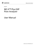
N UFLO™
MC-II™ Flow Analyzer
CE-Approved
QuickStart
Mount the MC-II
Direct Mount
(For remote mount instructions,
see the MC-II User Manual.)
1. Plug the MC-II cable connector into
the pickup and turn the swivel
nut clockwise until the connector
is fully inserted into the pickup and
the swivel nut is hand-tight.
2. Loosen the locking screws that
secure the base MC-II mount.
3. Position the MC-II on the flowmeter, carefully pulling excess
signal cable through the strain relief
cord connector on the side of the
upper mount.
4. Thread the base of the mount onto
the conduit adapter of the turbine
meter and tighten two extra rounds
after it is hand-tight. DO NOT allow
the upper mount and MC-II readout
to turn while tightening the base to
avoid damaging the signal cable.
5. Tighten the outside nut of the strain
relief cord connector on the upper
mount with a 15-mm open-end
wrench to prevent cord slippage.
6. If necessary, adjust the MC-II readout for best viewing. Loosen the
nut on the bolt that holds the MC-II
readout on the upper mount, tilt
the unit to the desired angle and
retighten the nut.
For complete
instructions,
see the MC-II
Flow Analyzer
(CE-Approved)
User Manual,
(Part No.
9A-50165011).
Install Field Wiring
Connect the battery and
flowmeter signal cable
as shown at right.
TFM
SIGNAL
CAMERON
I.S. BATTERY
P/N 9A-90099000
FLOWMETER
INPUT
TFM
SIGNAL
CHASSIS
GROUND
CHASSIS
GROUND
9A-
CAUTION: The lithium battery that powers
the MC-II is sealed, but a battery leak could
expel toxic fumes into the MC-II enclosure. Before
opening the enclosure, make sure the enclosure
is in a well-ventilated area and avoid breathing
fumes that could be trapped inside. See Appendix
A of the MC-II Flow Analyzer User Manual (Part No.
9A-50165011) for instructions on battery disposal
and a link to the MSDS sheet for the MC-II battery.
DOTTED LINES INDICATE
OPTIONAL SHIELDING
CONNECTIONS
B
A
Calibrate the MC-II
The following information is needed to calibrate the
MC-II:
• unit of measure for volume
• flowmeter calibration factor (pulses per gallon)
• unit of measure for flow rate
1. Press and hold ACCESS for 3 seconds, then
release, to enter Calibrate mode. Prog.no will
appear in the top display and the version number
of the firmware will appear in the bottom display.
The tot.Eng menu will then appear in the top
display, and the default volume unit - bbL - will
appear in the bottom display.
2. Press INCREMENT until the desired unit of
measure appears in the bottom display. Press
ENTER/STEP.
• If you select a preprogrammed unit (bbl, gal,
m3, liter), Pu.P.gAL will appear in the top
display. Go to Step 3 for instruction on entering your flowmeter’s calibration factor (in
pulses per gallon). The MC-II will automatically
calculate the divisor.
• If you select uSEr, Ent.diV will appear in
the top display. Enter a calculated divisor
(in terms of specified unit) from right to left.
Press INCREMENT to select each digit; press
ENTER/STEP to advance to the next digit.
Proceed to Step 4.
Uo:
Io:
Po:
Ci:
Li:
3.9V
1.82 mA
1.77 mW
0
0
barrels
gallons
cubic meters
liters
user-defined
3. Locate the flowmeter calibration factor (pulses per gallon) on a plastic tag
attached to the meter. Enter the number as follows:
a. Press DEC. POINT repeatedly to position your decimal point for the
calibration factor.
b. Enter the digits from right to left, beginning with the flashing digit to the far
right.
c. Press INCREMENT to select digits between 0 and 9 (or press and hold
INCREMENT to scroll the digits). Press ENTER/STEP to save the selection.
Repeat this step to enter all six
digits. If your calibration factor
is less than six digits in length,
barrels
per day
enter 0 for remaining digits.
When the last (sixth) digit is
saved, the calibration factor will
gallons
<unit>
per minute
per day
be saved in the MC-II’s memory
and rAt.Eng will appear in the
cubic meters
<unit>
per day
per hour
top display.
4. At the rAt.Eng prompt, select
liters
<unit>
per minute
per minute
a unit of measure for rate. Press
INCREMENT until the desired unit
<unit>
per second
appears in the bottom display. If
you selected a user-defined unit
of measure for volume in Step 2, the rate options will be per day, per hour, per
minute, or per second. Press ENTER/STEP. PULSE will appear in the top display.
5. Deselect the Pulse Output option by pressing ENTER/STEP to accept the
default setting (OFF). CodE will appear in the top display.
6. Enable or disable the password-protected security feature. Press ENTER/STEP
to retain the default NO setting or press INCREMENT to toggle the setting to
YES (password protection enabled). Press ENTER/STEP. If you select YES, a data
entry field will appear in the bottom screen. Enter a numeric password containing up to six digits. Remember your password! You will be asked for it each time
you press ACCESS (to enter the Calibration mode) or RESET (to zero the total).
7. The SEt.tot (preset total) menu will appear. To bypass this menu and complete
the configuration, press ENTER/STEP. To preset a total, press INCREMENT to
toggle the setting to YES; then press ENTER/STEP. Enter the digits of the total,
right to left, pressing INCREMENT to select each digit, and pressing ENTER/
STEP to save the selection. When the last digit has been entered and saved,
the prompt SAVING will appear in the lower display while the calibration settings are saved to nonvolatile memory. The calibration process is complete.
Part No. 9A-50165012, Rev. 01