1
SSI Link Analyser User Manual
Park Signalling
Limited
www.park-signalling.co.uk
PS/PSL-RD-014/MAN/008 Issue 4
Park Signalling Limited ©2006
Page 1 of 21
SSI Link Analyser
User Manual
PS/PSL-RD-014/MAN/008
Issue 4
CONTENTS
1.
INTRODUCTION ..........................................................................................................................3
1.1.
1.2.
1.3.
1.4.
Purpose...............................................................................................................................................3
Scope..................................................................................................................................................3
Abbreviations.....................................................................................................................................3
Definitions .........................................................................................................................................3
2.
STORAGE AND HANDLING ......................................................................................................4
3.
SOFTWARE INSTALLATION ....................................................................................................5
4.
SSI LINK ANALYSER - GETTING STARTED..........................................................................6
4.1.
4.2.
5.
SLA COMPONENTS ....................................................................................................................7
5.1.
5.2.
5.3.
5.4.
5.5.
5.6.
6.
Log Options - Events .......................................................................................................................13
Log Options - File............................................................................................................................13
Log Entries.......................................................................................................................................14
TRIGGERING..............................................................................................................................17
8.1.
8.2.
8.3.
8.4.
9.
Normal View....................................................................................................................................10
Zoom View ......................................................................................................................................12
SLA Statistics...................................................................................................................................12
LOGGING ....................................................................................................................................13
7.1.
7.2.
7.3.
8.
Laptop PC (ST 130) ...........................................................................................................................7
Master Module (ST 101)....................................................................................................................8
Optical Fibre (ST 110) .......................................................................................................................8
Test Point Adaptor (ST 112)..............................................................................................................8
Trigger Module (ST 121)...................................................................................................................9
Peripheral Power Lead (ST 120)........................................................................................................9
DISPLAYS ...................................................................................................................................10
6.1.
6.2.
6.3.
7.
Running the SLA ...............................................................................................................................6
Operation Overview...........................................................................................................................6
Trigger Setup Window.....................................................................................................................17
OR Trigger Example 1 – Repeatedly display reply telegram 23 on an oscilloscope.......................18
OR Trigger Example 2 – Trigger once when TFM 47 reports an input or output failure................18
Sequential Trigger Example – Trigger each time a signal is changed to red...................................19
MENUS ........................................................................................................................................20
PS/PSL-RD-014/MAN/008 Issue 4
Park Signalling Limited ©2006
Page 2 of 21
1.
INTRODUCTION
1.1.
Purpose
This document provides user instructions for Park Signalling’s SSI Link Analyser (SLA).
1.2.
Scope
This document covers operation of the SLA. To prevent duplication of information it is
assumed that the user has read all the warnings, cautions and safety information provided by
the manufacturer of the PC.
1.3.
Abbreviations
ID
LDT
PC
SLA
SSI
TFM
USB
1.4.
Identity
Long Distance Terminal (part of SSI)
Personal Computer
SSI Link Analyser
Solid State Interlocking
Trackside Functional Module (part of SSI)
Universal Serial Bus
Definitions
Glitch
A glitch is a high to low transition (on the data link) that is not part of a
complete telegram.
Manchester
coding
To provide protection from corruption, telegrams are Manchester coded:
each bit is represented by two line states of opposite polarity. If the SLA
detects an error in the coding, the coding error count is incremented and
the telegram is deemed invalid.
Missing telegram
If a telegram is absent or deemed invalid (i.e. has coding or parity errors),
the missing telegram count will be incremented. Note that the SLA must
have previously seen a telegram at a particular address before it can
detect that telegram's absence.
Parity
To provide protection from corruption, a telegram has five parity bits at
its end. If the SLA detects an error in the parity bits, the parity error count
is incremented and the telegram is deemed invalid.
PS/PSL-RD-014/MAN/008 Issue 4
Park Signalling Limited ©2006
Page 3 of 21
2.
STORAGE AND HANDLING
The SLA should be stored in a dry environment with a temperature range of -20 to 50°c.
When the PC is powered from its battery, the SLA may be operated in the same environment
as an SSI data link module. If the PC is a.c. powered, its power supply must be sheltered from
any moisture.
It is recommended that any exposed connectors should have their covers placed over them, in
order to limit any damage to or dirtying of the connections.
The minimum bend radius of the Optical Fibre is 17mm; further bending may damage the
fibre, causing unreliable operation.
As the SLA is electronic equipment, please dispose of it responsibly when it is lifeexpired.
PS/PSL-RD-014/MAN/008 Issue 4
Park Signalling Limited ©2006
Page 4 of 21
3.
SOFTWARE INSTALLATION
You will need administrative rights in order to carry out the installation and enter the licence
code.
If the SLA software is not pre-installed on the PC, double-click the ‘SLA_x_yy.msi’ file on the
installation CD (where SLA version = x.yy), and follow the on-screen instructions.
When the SLA software is first run, it will provide you with a licence request code to quote to
Park Signalling; this will allow a licence code to be generated for you. Note that the SLA will
not function until a valid licence code has been entered.
PS/PSL-RD-014/MAN/008 Issue 4
Park Signalling Limited ©2006
Page 5 of 21
4.
SSI LINK ANALYSER - GETTING STARTED
The SLA is a PC-based test tool providing a means to observe and record all messages being
transferred on an SSI Trackside Data Link, in real-time†. Additionally, the SLA detects line
glitches and corrupt / absent telegrams.
4.1.
Running the SLA
•
•
•
•
•
Ensure the SLA components are in good condition and have no visible damage.
Ensure the SLA is not and will not be exposed to rain, sleet or snow (though limited
splashes of rain will not affect the SLA’s operation).
Connect all the SLA components (see section 5).
Run the SSI Link Analyser program on the laptop PC (if the program is already running,
select the 'Reset All' command from the Monitor Menu).
The SLA program will start in the Normal View. The SLA is operational when the status
bar shows that the SLA is monitoring.
When the SLA starts monitoring it will learn which command and reply telegrams are being
transmitted on the Data Link; this information is necessary for detection of missing telegrams.
The SLA has two different display modes: Normal View and Zoom View.
4.2.
Operation Overview
The SLA detects Manchester coding errors, parity errors, missing telegrams and glitches. If a
coding or parity error is detected, the data contained in the telegram is deemed invalid and is
discarded; this will also cause a missing telegram to be logged (in addition to the coding or
parity error).
If a telegram is missing (or its sync or timing bits have been corrupted), it will be reported and
logged as missing; the data and status display will be cleared until a valid telegram is received
again.
Other features of the SLA are:
•
•
Logging events to hard disk (see section 7)
Triggering other test equipment (see section 8)
†
Note that only telegrams present on the local baseband data link can be monitored. Thus, for SSI schemes
utilising LDTs, not all reply telegrams will necessarily be visible when monitoring at a trackside location.
PS/PSL-RD-014/MAN/008 Issue 4
Park Signalling Limited ©2006
Page 6 of 21
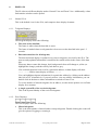
5.
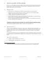
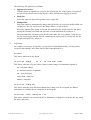
SLA COMPONENTS
Peripheral
Power Lead
expansion port
Trigger
out
Tgm
out
USB
port
PC
conn
Trigger
Module
expansion port
expansion port
Laptop PC
Optical
input
Serial
port
Master
Module
PC
conn
Optical Fibre
4mm plugs to
Data Link test
points
Test Point Adaptor
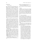
The SSI Link Analyser (SLA) comprises the following:
•
•
•
•
•
•
5.1.
Laptop PC [ST 130]
Master Module [ST 101]
Optical Fibre [ST 110]
Test Point Adaptor [ST 112]
Trigger Module [ST 121] (optional)
Peripheral Power Lead [ST 120] (optional)
Laptop PC (ST 130)
The Laptop PC is used to run the SSI Link Analyser user interface software (ST 135)
The PC needs a serial port (9-way D-type plug) for connection to the Master Module, and a
USB port for connection to the Peripheral Power Lead.
Minimum PC specification
Operating system Microsoft Windows 2000 (or later)
Processor
Pentium M Processor 900MHz
RAM
256MB
Display
1024x768 pixels, 16 million colours
It is strongly recommended that no other applications are run at the same time as the
SSI Link Analyser; this is to preserve accurate timing measurements.
PS/PSL-RD-014/MAN/008 Issue 4
Park Signalling Limited ©2006
Page 7 of 21
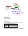
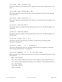
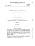
5.2.
Master Module (ST 101)
expansion port
Optical
input
Master
Module
PC
conn
The Master Module performs the low level decoding of telegrams from the data link, and
passes the telegram data to the PC. It is powered solely from the PC.
The Master Module has the following connections:
•
•
•
Optical SMA jack, for connection to the Optical Fibre,
Expansion port socket (25-way female D-type) for connection to the Trigger Module (or
any future modules),
A flying lead terminated with a 9-way female D-type, for connection to the Laptop PC’s
serial port.
When no peripheral modules are in use, the Master Module’s only power source shall be the
Laptop PC’s serial port.
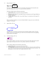
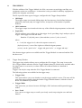
5.3.
Optical Fibre (ST 110)
Optical Fibre
The Optical Fibre provides the connection between the Master Module and the Test Point
Adaptor. The use of an optical fibre gives robust electrical isolation between the signalling
system and the Link Analyser.
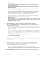
5.4.
Test Point Adaptor (ST 112)
Test Point Adaptor
The Test Point Adaptor converts the electrical (current loop) data link signal into an optical
signal, and provides protection from reverse polarity connection to the data link.
The Test Point Adaptor has the following connections:
•
•
Optical SMA jack, for connection to the Optical Fibre,
Two flying leads terminated with 4mm ‘banana’ plugs, for connection to the data link test
points (the current loop interfaces provided at the interlocking and lineside locations). The
4mm plugs are colour coded; red for signal and black for return.
PS/PSL-RD-014/MAN/008 Issue 4
Park Signalling Limited ©2006
Page 8 of 21
5.5.
Trigger Module (ST 121)
expansion port
Trigger
out
Tgm
out
Trigger
Module
expansion port
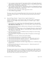
The Trigger Module is an optional component that allows the SLA to connect to and trigger
ancillary test equipment, such as an oscilloscope. A connection is also provided for ancillary
equipment to monitor the telegram patterns.
The Trigger Module has the following connections:
•
•
•
•
'Trigger out' BNC jack, for connection to ancillary test equipment (e.g. oscilloscope).
When a trigger event occurs, a falling edge will be present on this output.
'Telegram out' BNC jack, for connection to ancillary test equipment.
Expansion port socket (25-way female D-type) for connection to the Peripheral Power
Lead.
Expansion port plug (25-way male D-type) for connection to the Master Module.
The BNC outputs are TTL compatible, and are electrically isolated from each other and all
other components of the SLA.
The Trigger Module is powered from the PC's USB port, via the Peripheral Power Lead.
5.6.
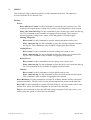
Peripheral Power Lead (ST 120)
Peripheral
Power Lead
PC
conn
The Peripheral Power Lead provides the power connection from the Laptop PC to peripheral
modules (i.e. the Trigger Module or any future modules). The Peripheral Power Lead is not
needed for the Master Module alone. It is only needed when peripheral modules are in use.
The Peripheral Power Lead has the following connections:
•
•
Expansion port plug (25-way male D-type), for connection to the Trigger Module,
USB type A plug for sourcing power from the Laptop PC’s USB port.
PS/PSL-RD-014/MAN/008 Issue 4
Park Signalling Limited ©2006
Page 9 of 21
6.
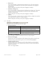
DISPLAYS
The SLA has two different display modes: Normal View and Zoom View. Additionally, a data
link statistics window can be opened.
6.1.
Normal View
This is the default view for the SLA, and comprises three display elements.
6.1.1. Telegram Displays
The telegram display shows the following:
•
The state of the data link,
The frame is white when the data link is active.
The frame is hashed when no telegrams have been seen on the data link in the past 1.2
seconds.
•
Data and status bits for all telegrams,
The data and status display is updated every time a telegram is received by the SLA. The
most recently updated information is marked with a small red dot in the centre of the data
bits.
When any data or status bits change, their background colour will change to yellow (to
highlight the change), and then slowly fade back to grey.
If no valid telegram has been seen for a particular address, its data display will show
---- ---- and its status display will show -----.
You can highlight telegram information for a particular address by clicking on the address
label (00 to 63). Alternatively, if you only wish to view one address' information, you can
double click on the data or status information to switch to Zoom View.
To see the number of missed telegrams for an address, rest the mouse pointer over its Data
display for a moment.
•
A single system ID of the received telegrams.
This is the System Identity of the received telegrams.
6.1.2. Error Displays
The error displays show the following:
•
Missed telegrams,
This is the total number of missed and/or corrupt telegrams. Double clicking the count will
give the option of logging or resetting it.
PS/PSL-RD-014/MAN/008 Issue 4
Park Signalling Limited ©2006
Page 10 of 21
•
Parity errors,
This is the total number of telegrams that have had parity errors. The missed telegram
count will also be incremented every time this count is incremented, as the telegram is
deemed invalid.
Double clicking the count will give the option of logging or resetting it.
•
Manchester coding errors,
This is the total number of telegrams that have had Manchester coding errors. The missed
telegram count will also be incremented every time this count is incremented, as the
telegram is deemed invalid.
Double clicking the count will give the option of logging or resetting it.
•
Glitches.
This is the total number of glitches detected. A glitch is defined as a high to low transition
on the data link that is not part of a complete telegram.
Double clicking the count will give the option of logging or resetting it.
6.1.3. Status Bar
The status bar shows the following (from left to right):
•
The state of the SLA
Display
Waiting for SLA to initialise
Waiting for reply from SLA hardware
SLA hardware error - check and reset
Monitoring - Data Link Active
Monitoring - Data Link Idle
Meaning
The PC is trying to detect the SLA Master Module.
The PC has detected the SLA Master Module, and is waiting for
a reply from it (should last no longer than 1 second).
An initialisation error has occurred, Reset All should be pressed.
The SLA is monitoring telegrams on the data link.
The SLA is active, but no telegrams have been seen in the past
1.2 seconds (or the data link is not connected).
•
The number of TFMs present,
This is the number of TFMs from which the SLA has seen reply telegrams.
•
The state of the logging,
When the log is active the log filename will be displayed, along with its current file size.
Each time an entry is placed in the log, the save icon will be briefly highlighted.
•
Peripheral modules present.
Peripheral modules can be connected to the SLA Master Module to provide enhanced
functionality. Mnemonics will be displayed on the status bar to show which peripheral
modules are connected.
TRG = SLA Trigger Module.
PS/PSL-RD-014/MAN/008 Issue 4
Park Signalling Limited ©2006
Page 11 of 21
6.2.
Zoom View
It is envisaged that you will not always need to see all telegrams simultaneously. The Zoom
View provides a means to focus on a single telegram address.
In Zoom View the SLA displays,
•
•
•
Data and status bits for the command and reply telegrams of one address only,
The System ID of each of the two telegrams being observed,
A missed telegram count for each of the two telegrams being observed.
When the data or status bits of a telegram change, the SLA highlights the individual bits that
have changed.
Note that Zoom View only affects the way that telegram information is displayed; the SLA
still monitors all telegrams and errors, logging to file as required.
Zoom View is accessed from the Normal View window using the View menu, or by double
clicking on a telegram's data or status bits.
6.3.
SLA Statistics
This window is opened from the Show Statistics menu, and displays the following telegram
statistics:
•
•
•
•
•
Frequency of missed telegrams,
Frequency of glitches,
Number of received telegrams (total and per address),
Missing telegram count for each address,
Percentage telegram error for each address.
The display can be updated by clicking the 'Refresh' button.
If you wish to save a copy of the statistics, the 'Save to file' button will let you create a tab
delimited text file (for importing into a spreadsheet or text editor).
The information table can be sorted by clicking on any of the column headers.
PS/PSL-RD-014/MAN/008 Issue 4
Park Signalling Limited ©2006
Page 12 of 21
7.
LOGGING
The SLA provides time stamped logging of events to the Laptop PC’s hard disk. The time is
based on the PC's internal clock, and has a resolution of 10ms.
All log settings are made in the Log Options window (opened from the Log menu).
The log options window allows you to change settings for the log file, as well as start and stop
logging.
7.1.
Log Options - Events
The log options window lets you choose which events you would like to be logged to disk
from the following:
•
Erroneous telegrams,
Tick this option to log the occurrence of any invalid telegrams.
•
Missing telegrams,
Tick this option to log when a telegram is missing.
•
Glitches,
Tick this option to log all glitches. The log will show how many glitches were seen
preceding a particular telegram.
•
All valid telegrams,
Tick this option to log all valid telegrams. Note that this option will produce a very large
log file.
•
Learnt telegrams,
Tick this option to log when the first telegram is seen from each address.
•
Telegram changes,
Tick this option to only log telegrams when their Data or Status changes. This option
keeps log files to a reasonable size, while still recording all state changes on the data link.
•
Exclude address 0.
Tick this option to NOT log any data/status changes for address 0.
Address 0 is used by the diagnostic processor module in the interlocking, and changes
every major cycle. This option keeps log files to a reasonable size, while still recording all
state changes on the data link.
When logging is started, a list of the event types to be logged will be saved in the log file.
Additionally, the current state of all the telegrams will be saved in the log file (this is useful
when only telegram changes are being logged).
7.2.
Log Options - File
To choose a log file click the Change button; after choosing, the filename will be displayed
beside the button. If the log is currently active, the previous log file will be automatically
stopped, and the new file started; no events will be missed from the log.
PS/PSL-RD-014/MAN/008 Issue 4
Park Signalling Limited ©2006
Page 13 of 21
The following file options are available:
•
Append new entries,
Tick this option to append new events to the selected log file. If this option is not ticked,
any previously stored events in the log file will be deleted when logging is started.
•
Single file,
Select this option to place all log entries into a single file.
•
Multiple files.
Select this option to automatically change the log file after it reaches the defined Max size
(in Mbytes). The size can be set to any integer from 1 to 100 inclusive.
When the multiple files option is selected, the chosen log file will become the log index,
having the filename, start time and stop time of each individual file written to it.
The individual files will have names based on the index file. For example, if the chosen
log file is newlog.sla then the first file containing log entries will be newlog.001.sla, the
second newlog.002.sla, and so on.
7.3.
Log Entries
An example of each type of log entry is given below (listed alphabetically). All log entries,
except for date changes, have their times in the format hh:mm:ss.ss.
27/03/05
This shows when a new day began.
13:31:04.59
Change
39
0
09
0100 0000
00000
This shows when the SLA saw either a data or status change for command telegram 39.
39 = telegram address
0 = data direction (0=command)
09 = system identity
0100 0000 = data bits
00000 = status bits
13:31:09.74
Coding err
This shows when the SLA detected a Manchester coding error in a telegram; no address
information is available due to corruption of the telegram.
13:31:24.87
Count: coding err = 63
This shows when the user inserted the SLA's Manchester coding error count into the log, using
the errors sub-menu.
PS/PSL-RD-014/MAN/008 Issue 4
Park Signalling Limited ©2006
Page 14 of 21
13:31:24.87
Count: glitches = 509
This shows when the user inserted the SLA's glitch count into the log, using the errors submenu.
13:31:24.86
Count: missed tgms = 328
This shows when the user inserted the SLA's missed telegram count into the log, using the
errors sub-menu.
13:31:24.87
Count: parity err = 2
This shows when the user inserted the SLA's parity error count into the log, using the errors
sub-menu.
13:31:04.07
Data link active
This shows when a previously idle data link became active (or the Test Point Adaptor was
connected).
14:04:35.07
Data link timeout
This shows when a previously active data link became idle (or the Test Point Adaptor was
disconnected).
13:31:09.29
Glitch * 127 ->
16 1
This shows when the SLA detected 127 glitches. The glitches preceded reply (data
direction=1) telegram 16.
13:31:04.11
Learn
03
0
Follows 02 1
This shows when the SLA first saw command (data direction=0) telegram 03, and that it
followed reply (data direction=1) telegram 02.
14:05:27.54
Mem261271
27
0
09
1001 0000
00000
Displayed at the start of logging, this shows the current state of command telegram 27 in the
SLA's memory.
Mem = current memory
261 = the preceding telegram in the major cycle is address 26 reply (data direction=1)
271 = the proceeding telegram in the major cycle is address 27 reply (data direction=1)
09 = system identity
1001 0000 = data bits
00000 = status bits
PS/PSL-RD-014/MAN/008 Issue 4
Park Signalling Limited ©2006
Page 15 of 21
13:31:09.29
Missing
58
1
This shows when the SLA detected that reply telegram 58 was absent.
13:31:09.74
Parity err 11
0
09
1110 0001
11111
This shows when the SLA detected a parity error in command (data direction=0) telegram 11.
As a parity error deems the telegram invalid, the system identity, data bits and status bits are
shown for information only.
14:05:30.24
Reset All...
This shows when the user executed a Reset All command.
14:05:32.38
Reset Hardware...
This shows when the user executed a Reset Hardware command.
13:30:57.09
Start log
26/03/05
This shows the time and date when logging started.
13:31:29.71
Stop log
26/03/05
This shows the time and date when logging stopped.
13:31:05.00
Tgm
07
1
09
1010 0001
11111
This shows when the SLA saw reply telegram 07 (but no data or status changes occurred).
07 = telegram address
1 = data direction (1=reply)
09 = system identity
1010 0001 = data bits
11111 = status bits
PS/PSL-RD-014/MAN/008 Issue 4
Park Signalling Limited ©2006
Page 16 of 21
8.
TRIGGERING
With the addition of the Trigger Module, the SLA can connect to and trigger ancillary test
equipment, such as an oscilloscope. A connection is also provided for ancillary equipment to
monitor the telegram waveforms.
The SLA provides three types of trigger, configured in the Trigger Setup window:
•
OR Single
The trigger output is activated (falling edge) the first time any of the defined telegram
patterns are detected (only one trigger occurs, irrespective of the number of patterns
defined).
•
OR Continuous
The trigger output is activated each time any of the defined telegram patterns are detected.
•
Sequential
The SLA allows you to define up to eight trigger levels, providing a logic analyser style of
trigger. Each trigger level has the form:
Level n: If {defined pattern} detected then {action 1} else {action 2}
where
n = 1 to 8 (the trigger level, where the sequence starts at 1)
{defined pattern} is one of the eight user-defined telegram patterns
{action} can be ‘goto level n’, ‘trigger and goto level n’, or ‘trigger and stop’.
Note that no trigger options are available until the Trigger Module is connected and the SLA
has been reset.
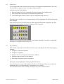
8.1.
Trigger Setup Window
The trigger setup window allows you to configure the SLA trigger. The setup is sent to the
SLA Trigger Module when the Send to Trigger Module button is clicked (only available when
the trigger state is set to active) or when a Reset All or Reset Hardware command is
performed.
Triggers can only be setup when the SLA Trigger Module is connected.
The following options are available for the trigger setup:
•
Trigger State
This option allows you to set whether or not the trigger module is active. This state will be
sent to the trigger module when the Send to Trigger Module button is clicked or when a
Reset All command is performed.
•
Trigger Mode
This option lets you choose between OR Single, OR Continuous and Sequential trigger
modes.
•
Save / Load
You can save a trigger setup or recall a previously saved setup using the save and load
buttons.
PS/PSL-RD-014/MAN/008 Issue 4
Park Signalling Limited ©2006
Page 17 of 21
•
Telegram patterns
Up to eight telegram patterns can be created, which the SLA Trigger Module compares
against received telegrams.
You can add a new telegram pattern by clicking on the Add button; this will open the
pattern editor window.
You can edit an existing telegram pattern by clicking on the pattern and then the Edit
button; this will open the pattern editor window.
You can delete a telegram pattern by clicking on the pattern and then the Delete button.
Note that you cannot delete a pattern if it is currently used in the trigger sequence.
You can edit the name of a pattern by slowly clicking twice on its name.
When part of a pattern is X, the Trigger module will not compare that part of the pattern
with the received telegram (i.e. it is a 'don't care' condition).
•
8.2.
Trigger sequence
When the Trigger Mode is 'Sequential', the trigger sequence is shown at the bottom of the
trigger setup window. You can edit the sequence by clicking on any underlined parts of it,
and choosing from the pop-up list.
OR Trigger Example 1 – Repeatedly display reply telegram 23 on an oscilloscope
This is the simplest trigger scenario for the SLA. If you wish to see the waveform of reply
telegram 23, follow these steps:
1. Connect the Trigger Module's trigger output to the scope's trigger input, and set the scope's
trigger slope to falling edge. The trigger module's telegram output should be connected to
a channel of the scope.
2. Delete any existing telegram patterns by clicking on each pattern and then clicking delete.
3. Create a pattern for command telegram 23‡ by clicking add. The pattern's values should be
Data Direction 0, System ID XX, Address 23, Data XXXXXXXX, Status XXXXX, Parity
Valid, Manchester coding Valid.
4. Set the trigger mode to 'OR' continuous, and the trigger state to Active.
5. Click on Send to Trigger Module.
The trigger output will be activated (falling edge) at the end of each valid command telegram
having address 23. By adjusting the trigger delay on the oscilloscope, the next telegram (reply
23) will be visible.
8.3.
OR Trigger Example 2 – Trigger once when TFM 47 reports an input or output failure
If you wish to output a single trigger pulse when TFM 47 reports either an input interface
failure or an output interface failure, follow these steps:
1. Connect the Trigger Module's trigger output to your ancillary test equipment.
2. Delete any existing telegram patterns by clicking on each pattern and then clicking delete.
‡
Note that if monitoring at an interlocking using LDTs, reply telegram 23 will follow command telegram 24.
PS/PSL-RD-014/MAN/008 Issue 4
Park Signalling Limited ©2006
Page 18 of 21
3. Create a pattern for reply telegram 47 input interface failure by clicking add. The pattern's
values should be Data Direction 1, System ID XX, Address 47, Data XXXXXXXX, Status
XXX0X, Parity Valid, Manchester coding Valid.
4. Create a pattern for reply telegram 47 output interface failure by clicking add. The pattern's
values should be Data Direction 1, System ID XX, Address 47, Data XXXXXXXX, Status
XX0XX, Parity Valid, Manchester coding Valid.
5. Set the trigger mode to 'OR' single, and the trigger state to Active.
6. Click on Send to Trigger Module.
The trigger output will be activated (falling edge) the first time that either of the status bits 2
or 3 are zero in reply telegram 47. These bits represent input and output interface failures
respectively.
8.4.
Sequential Trigger Example – Trigger each time a signal is changed to red
Using the sequential trigger, you can output a trigger each time a signal is commanded to
change to red. This example assumes that the red aspect is on TFM 21 output 7, and the
system ID is 04.
1. Create a pattern for the signal being red by clicking add. The pattern's values should be
Data Direction 0, System ID 04, Address 21, Data 1XXXXXXX, Status XXXXX, Parity
Valid, Manchester coding Valid.
2. Rename the pattern just created to 21Red by slowly clicking twice on the existing name,
then typing the new name.
3. Create a pattern for the signal being not red by clicking add. The pattern's values should be
Data Direction 0, System ID 04, Address 21, Data 0XXXXXXX, Status XXXXX, Parity
Valid, Manchester coding Valid.
4. Rename the pattern just created to 21NotRed by slowly clicking twice on the existing
name, then typing the new name.
5. Set the trigger mode to Sequential; the setup window will expand to reveal the trigger
sequence.
6. If the sequence is not clear, click the Clear sequence button.
7. Click on the line following 'Level 1 If' and choose 21NotRed
8. Click on the line following 'then' and choose 'goto level...' followed by 'goto level 2'.
9. Click on the line following 'else' and choose 'goto level...' followed by 'goto level 1'.
10. Click on the line following 'Level 2 If' and choose 21Red
11. Click on the line following 'then' and choose 'trigger and goto level...' followed by 'trigger
and goto level 1'.
12. Click on the line following 'else' and choose 'goto level...' followed by 'goto level 2'.
13. Set the trigger state to Active.
14. Click on Send to Trigger Module.
The trigger sequence starts at level 1, looking for the 21NotRed pattern. When 21NotRed is
seen, the sequence will move to level 2, looking for the 21Red pattern. When 21Red is seen,
the trigger output will be activated, and the sequence will restart. Thus, the trigger output is
only activated when a transition to the red aspect occurs.
PS/PSL-RD-014/MAN/008 Issue 4
Park Signalling Limited ©2006
Page 19 of 21
9.
MENUS
This section provides a short description of each command menu item. The menus are
accessed from the SLA's Normal View.
Monitor
Errors
Reset All Error Counts Use this command to reset all the error counts to zero. The
counts for missed telegrams, coding errors, parity errors and glitches will be cleared.
Place All Counts Into Log Use this command to place all the error counts into the log
file. This command is only available if logging has been started. The counts for
missed telegrams, coding errors, parity errors and glitches will all be logged.
Missing Telegrams
Reset count Use this command to reset the missing telegram count to zero.
Place count into log Use this command to place the missing telegram count into
the log file. This command is only available if logging has been started.
Coding Errors
Reset count Use this command to reset the coding error count to zero.
Place count into log Use this command to place the coding error count into the
log file. This command is only available if logging has been started.
Parity Errors
Reset count Use this command to reset the parity error count to zero.
Place count into log Use this command to place the parity error count into the log
file. This command is only available if logging has been started.
Glitches
Reset count Use this command to reset the glitch count to zero.
Place count into log Use this command to place the glitch count into the log file.
This command is only available if logging has been started.
Reset Hardware Use this command to reset the SLA Master Module and any connected
peripheral modules. The SLA will re-learn which telegrams are present on the data link.
Reset All Use this command to reset the SSI Link Analyser. All error counts will be reset,
and the SLA will re-learn which telegrams are present on the data link.
Exit Use this command to close the SSI Link Analyser program. If the log is active, you
will be given the option to cancel the exit command.
PS/PSL-RD-014/MAN/008 Issue 4
Park Signalling Limited ©2006
Page 20 of 21
View
Show Statistics Use this command to display the SLA Statistics window.
Toggle Address Highlight Use this command to toggle an address highlight on / off. The
highlight can also be toggled by clicking on the telegram address.
Clear All Highlights Use this command to clear all the address highlights from the
telegram displays. To set or clear highlights for individual addresses, use the Toggle
Address Highlight command.
Zoom On Address Use this command to switch to Zoom View.
Log
Log Options Use this command to open the Log Options window.
Start Logging Use this command to start logging events to disk. This command is only
available if a log file has been chosen in the Log Options window, and logging is currently
inactive.
Stop Logging Use this command to stop logging events to disk. This command is only
available if logging is currently active.
Trigger
Setup Trigger Use this command to open the Trigger Setup window. The trigger setup
window is only available when the SLA Trigger Module is connected to the SLA Master
Module.
Help
SSI Link Analyser Help Use this command to open this help file at the contents page.
What's This? Use this command to change the mouse pointer to
be displayed for a particular area of the screen by clicking on it.
. Help text will then
About SSI Link Analyser Use this command to display the version numbers of the SLA
software and the SLA Master Module.
PS/PSL-RD-014/MAN/008 Issue 4
Park Signalling Limited ©2006
Page 21 of 21