1
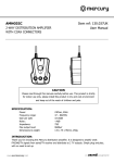
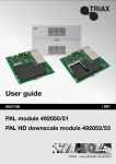
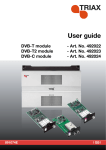
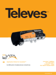
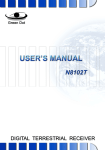
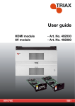
DECLARATION OF CONFORMITY TRIAX confirms that the product conforms to relevant EMC and LVD Directives (2004/108/EC and 2006/95/EC) harmonized standards and consequently can carry CE-mark. Relevant harmonized standards: EMC: EN 55013:2001/A1:2003/A2:2006, EN 55020:2007+A11:2011, EN 61000-3-2:2006/A1:2009/A2:2009, EN 61000-3-3:2008 LVD: EN 60065:2002+ A1:2006+A11:2008+A2:2010+A12:2011 KONFORMITÄTSERKLÄRUNG TRIAX bestätigt, dass das Produkt die EMC und LVD Richtlinien (2004/108/EC und 2006/95/EC) der harmonisierten Normen erfüllt und folglich das CE-Zeichen tragen darf. Relevante harmonisierten Normen: EMC: EN 55013:2001/A1:2003/A2:2006, EN 55020:2007+A11:2011, EN 61000-3-2:2006/A1:2009/A2:2009, EN 61000-3-3:2008 LVD: EN 60065:2002+ A1:2006+A11:2008+A2:2010+A12:2011 OVERENSSTEMMELSESERKLÆRING TRIAX bekræfter, at dette produkt opfylder de relevante EMC og LVD direktiver (2004/108/EF og 2006/95/EF) og harmoniserede standarder og dermed kan bære CE-mærket. Relevante harmoniserede standarder: EMC: EN 55013:2001 / A1: 2003/A2: 2006, EN 55020:2007 + A11: 2011, EN 61000-3-2:2006 / A1: 2009/A2: 2009, EN 61000-3-3:2008 LVD: EN 60065:2002 + A1: 2006 + A11: 2008 + A2: 2010 + A12: 2011 } Svend Kristiansen Quality manager Triax A/S Bjornkaervej 3 8783 Hornsyld Danmark User manual TFM 02 TRIAX IR link modulator TABLE OF CONTENTS PAGE 1. 1. Safety Precaution Safety Precaution…………………………………………………...2 To avoid electrical shock, do not take apart this device. 2. Technical specification…………………………………………….3 This device should use only the power supply included with it or provided as an accessory. 3. Kit Content…...………………………………………………………4 Do not overload wall outlets and extension cords as this can result in the risk of fire or electrical shock. 4. Installation and Operating Instruction…………………………..5-8 5. Troubleshooting …………………………………………………..9 6. Frequency Table ………………………………………………….10 Do not attempt to service this device yourself. Refer servicing to qualified personnel only. Caution: Changes or modifications not expressly approved by the Party responsible for compliance could void the user’s authority to 2 operate the equipment. 2 1 2 2. Technical Specification ITEM DESCRIPTION Modulator TV System Two Bit 7-segment LED DC Output (RF2) Regulated 9VDC 100mA Power Adapter PAL- G / I UHF: 470~862MHz Modulator Output Frequency Modulator CH Indicator Output Level ( 21-69CH ; Default Channel: CH36 ) (on 72 dBuV±4dB RF1/RF2 OUT) Gain (RF IN - RF1/RF2 OUT ) Return Path Gain(4MHz~8MHz) Input Voltage 100~240V 50/60Hz AC Output Voltage 9V/600mA DC Output Connector 5.5*2.1 DC Plug -10~10dB Adjustable > 10 dB (Peak Point:18dB+/-2dB) Carrier/Noise Ratio >48 dB Noise Figure < 4dB Maximum Output Level @60dB 3. Kit Content Modulator x1 90dBuV IMA3,EN50083-5 RF Input Connector F(f) RF Output Connectors F(f) AV Input/Output Connectors Power Adapter (9VDC/600mA) x1 RCA Port DC IN Connector Ø5.5*2.1 Socket IR Connector 3.5mm Socket IR Link Control Carrier Frequency(RF2 OUT to RF IN) On-off keyed 7.2MHz Video Input 1.0Vp-p/75Ω Audio Input 1.0Vp-p/600Ω 3 User’s Manual x1 4 4. i. Installation and Operating Instruction Panel Function 1:IR Transmitter Jack .3.5mm mono phone plug 2:DC Power Input. 9V DC 3:Power Switch 4:RF Input. This port can output 7.2MHz remote signal 5:RF Output 1 6:RF Output 2. This port output 9Vdc and input 7.2MHz remote signal 1 7:Gain control. Rotate this component can control the gain from RF input port to RF1 output and RF2 output port 8:A/V Input (RCA Socket) include one video input port and two audio input ports 9:A/V Output (RCA Socket) include one video output port and two audio output 2 8 3 4 5 ports 10: Display Screen. It can display CH number and audio carrier frequency. 6 9 7 11: Mode Switch. This button can switch between PAL-G and PAL-I system, 5.5 means PAL-G system and 6.0 means PAL-I system. 12: Channel Down Switch. 13: Channel Up Switch. 10 11 5 12 13 6 ii. Installation with RF cable. 5. The A/V signal from A/V Input is modulated as the RF signal, combined and amplified with the RF signal from RF IN, (then) output via RF 1 OUT and(or) RF 2 OUT of modulator. 6. Connect RF 1 OUT of the modulator to the main TV set in the lounge to watch programs. 7. Connect RF 2 OUT to a spare room TV set through an additional RF cable and Digital Link Eye(optional). Note: RF2 OUT IS WITH 9VDC voltage. Do not connect RF2 OUT to TV set directly without Digital Link Eye. 8. Plug the IR transmitter into IR jack on the modulator. Adjust the IR sensor toward the A/V signal source for an optimum reception. ii. 1. Operating Instruction Make sure the power adapter is connected to DC IN of the modulator. Turn the power switch to “ON”, then the CH number on Display Screen lights up. Fig.3 Application Diagram 2. There is -10~10dB (adjustable) gain from RF IN to RF1 OUT and RF2 OUT. When the power is on, the signal from RF IN can output to RF1 OUT and 1. Connect A/V signal source port to A/V Input on the modulator with RCA connector cable. RF2 OUT without additional amplifier. 3. 2. Connect A/V Output of the modulator to A/V Input on TV-like device set with up or down button firmly, the CH will be changed continuously, then RCA connector cable. A/V signals can be transferred from A/V Output of the modulator to A/V input of TV set. release the button until the CH stopping at your favor. 4. 3. Plug the provided power adapter into DC Power Input of the modulator. 4. Connect local cable TV or other signal source to RF IN of the modulator 7 Use Channel Selection Switches to select the desired channel. Push the When the A/V signal from A/V signal source is fed to the modulator, there will be the modulated signal output from the modulator. There won’t be any modulated signal output without A/V signal input. 8 5. Use the mode switch to change TV system, two figures will display on Display Screen, 5.5 or 6.0, and 5.5 means audio carrier frequency is 6. Frequency Table 5.5MHz, PAL-G system. Whereas, 6.0 stands audio carrier frequency is 6.0MHz, PAL-I system. Pushing CH switch or holding with no operation after one minute will exit mode state. 6. 7. Channel Frequency MHz Channel Frequency MHz Channel Frequency MHz 21 471.25 37 599.25 53 727.25 To watch the local cable TV programs from RF IN, the A/V signal from DVD 22 479.25 38 607.25 54 735.25 or Satellite Receiver must be turned off. 23 487.25 39 615.25 55 743.25 With A/V signal source remote controller aiming to the IR sensor of Digital 24 495.25 40 623.25 56 751.25 Link Eye, the controlling signal transmits through the RF cable to the 25 503.25 41 631.25 57 759.25 modulator, then outputs by IR transmitter to control the A/V signal source. 26 511.25 42 639.25 58 767.25 And if your signal source is SKY satellite receiver, it can be controlled 27 519.25 43 647.25 59 775.25 without IR transmitter, because its signal directly runs from RF output to 28 527.25 44 655.25 60 783.25 RF Input on modulator. 29 535.25 45 663.25 61 791.25 30 543.25 46 671.25 62 799.25 31 551.25 47 679.25 63 807.25 32 559.25 48 687.25 64 815.25 5. Troubleshooting i. No Image or Sound Make sure the power switch is switched to “ON” position 33 567.25 49 695.25 65 823.25 Check the connections of all connectors and plugs 34 575.25 50 703.25 66 831.25 Make sure the modulation and TV are tuned to the same channel 35 583.25 51 711.25 67 839.25 36 591.25 52 719.25 68 847.25 69 855.25 ii. Intermittence of Image and Sound Make sure the modulation and TV are using the free channel。 Shorten the distance of the signal transmission medium between modulator and TV keep the coaxial cable away from other cables if possible 9 10