1
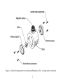
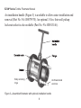
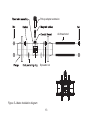
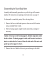
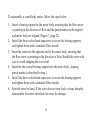
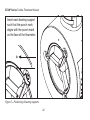
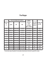
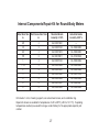
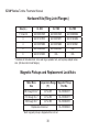
Class I, Group A, B, C, D, Division I
Complies with ASME Standard B31.3
NUFLO™
EZ-IN® Series
Turbine
Flowmeter
Installation Manual
Part No. 9A-100062997, Rev. 01
Measurement Systems
EZ-IN® Series BF Turbine Flowmeter Manual
Part No. 9A-100062997, Rev. 01
September 2008
© 2008 Cameron International Corporation (“Cameron”)
Printed in USA
All Rights Reserved
Table of Contents
Introduction................................................................................................. 5
Installation ............................................................................................... 10
Precautions........................................................................................ 10
Installation Procedure........................................................................ 11
Calibration................................................................................................ 12
Maintenance and Repairs........................................................................ 14
Removing the Meter from the Pipeline............................................... 14
Disassembling the Hex-Body Meter . ................................................ 15
Reassembling the Hex-Body Meter................................................... 16
Disassembling the Round-Body Meter.............................................. 19
Reassembling the Round-Body Meter............................................... 20
Returning the Meter to the Pipeline................................................... 23
Specifications and Parts Lists.................................................................. 24
Temperature and Pressure Ratings................................................... 24
Flow Ranges...................................................................................... 24
Internal Components Repair Kit for Hex-Body Meters....................... 25
iii
EZ-IN® Series Turbine Flowmeter Manual
Internal Components Repair Kit for Round-Body Meters................... 27
Retainer Rings for Hex-Body Meters................................................. 28
Hardware Kits and Centering Rings (Raised Face Flanges)............. 29
Hardware Kits (Ring Joint Flanges)................................................... 30
Magnetic Pickups and Replacement Lock Nuts................................. 30
iv
Introduction
The EZ-IN® Series Between-Flange Turbine Flowmeter measures
flowstream volume in flanged pipelines by transmitting electrical pulses to
readout instruments.
The flowmeter’s precision turbine has a rotational velocity proportional
to the linear velocity of the fluid flowing through the meter. As the turbine
rotates, the blades break magnetic lines of force set up by a magnetic pickup
screwed into the meter body. This penetration of the magnetic field creates
electrical pulses.
Internal components vary, depending on the size of the end connection.
The hex-body flowmeter shown in Figure 1, page 6, is designed with a 1-in.
end connection. The round-body flowmeter shown in Figure 2, page 7, is
designed with a 2-in. or larger end connection.
For installation, ANSI raised face or ring joint flanges and gaskets are
recommended as well as all-thread studs and nuts. Body centering rings and
flow straighteners can also be used.
EZ-IN® Series Turbine Flowmeter Manual
Conduit adapter
Downstream vane
Retainer ring
(2 typ.)
Rotor
Upstream vane
Figure 1—Internal components for hex-body flowmeters (1-in. end connection)
Figure 2—Internal components for round-body flowmeters (2-in. or larger end connection)
EZ-IN® Series Turbine Flowmeter Manual
An installation handle (Figure 3) is available to allow easier installation and
removal (Part No. 9A-100079570). An optional 3/4-in. thin-wall pickup
lock-nut socket is also available (Part No. 9A-100013146).
Body centering
rings
All-thread studs
and nuts
Figure 3—Assembled flowmeter with optional installation handle
Flowmeter identification data and specifications are engraved on the
flowmeter body or printed on a stainless steel tag, which is attached to the
meter body (Figure 4).
Figure 4—Product identification tag on flowmeter body
EZ-IN® Series Turbine Flowmeter Manual
Installation
Precautions
The EZ-IN® Series Between-Flange Turbine Flowmeter can be installed
vertically or horizontally. In either orientation, the arrow on the meter body
must point in the direction of flow in the line.
•
•
•
•
•
•
Before installing the meter, clean all upstream lines.
Do not blow out lines with compressed air or gas once the meter has
been installed.
Do not slug the meter with fluid. Carefully fill the line after installing
the meter. After startup, keep the meter full of fluid.
Never exceed the minimum or maximum recommended pressure and
temperature limits. See Temperature and Pressure Ratings, page 25.
Never exceed the maximum recommended flow rate for the meter. See
Flow Ranges, page 25.
Avoid hammer blows or other sharp impacts to the meter that could
damage internal parts.
10
•
•
•
•
If the end connection leaks at the time of installation, remove pressurebefore attempting to tighten the seal.
The customer is responsible for ensuring chemical compatibility
between the flowmeter and any fluids being metered.
The meter will attain the temperature of the fluid. Use caution when
touching the meter body to avoid burns.
Use appropriate bolts and hardware per ANSI B16.5 and, if applicable,
NACE MRO175 / ISO 15156.
Installation Procedure
1. Install a straight section of pipe on either side of the meter. This pipe
must be the same size as the meter end connection with a minimum
length of 10 pipe diameters upstream and 5 pipe diameters downstream.
For example, a flowmeter with a 6-in. end connection requires 6-in. pipe.
The section of pipe upstream must be 60 in.; the section downstream
must be 30 in.
2. To create a cradle for the meter, assemble all-thread studs, nuts, (centering rings, if purchased), and gaskets to connect the flanges using only
11
EZ-IN® Series Turbine Flowmeter Manual
2.
3.
4.
5.
the holes in the bottom half of the flanges (Figure 5, page 13). Install
additional nuts inside the flanges, if needed, to separate the flanges
while inserting the meter. (See “spreader” nuts in Figure 3, page 8.)
Lower the meter between the flanges and align the bore with the flowline. If centering rings are installed, the meter will rest on them.
Install the remainder of the all-thread studs and nuts through the holes
in the top half of the flanges.
Tighten the nuts.
Insert the magnetic pickup assembly into the flowmeter and turn it until
it is hand-tight, then back it out ¼ turn. Tighten the lock nut to prevent
the pickup from vibrating.
Calibration
The EZ-IN® Series flowmeter is precalibrated with water at the factory
and tagged with the calibration factor in pulses per gallon. For maximum
accuracy with fluids other than water, calibrate the meter with the desired
fluid in the flowline. This meter can be calibrated using any conventional
turbine meter calibration method.
12
Pickup adapter extension
All-thread stud
Spreader nut
Figure 5—Meter installation diagram
13
EZ-IN® Series Turbine Flowmeter Manual
Maintenance and Repairs
If flowmeter readings appear erratic, check the flowmeter for wear or debris.
Under normal operation with non-abrasive fluids, flowmeters can provide
years of service without repairs. If a flowmeter is exposed to abrasive fluids
or long periods of over-range flow rates, an annual check is recommended.
Removing the Meter from the Pipeline
1. Remove all pressure from the line.
2. Remove the magnetic pickup (Figure 5, Page 13) to avoid damaging it.
3. Remove one or more of the flange bolts.
4. Loosen the remaining flange bolt nuts to allow clearance for the meter.
If additional “spreader” nuts were installed, tighten them to help free
the meter.
5. Lift the meter from between the pipeline flanges, using an installation
handle if necessary (Figure 3, page 8).
14
Disassembling the Hex-Body Meter
Assembly and disassembly procedures vary with the type of flowmeter
installed. For instructions on repairing a round-body meter, see page 19.
To disassemble a hex-body meter, follow the steps below.
1. Remove the retaining ring from one end of the meter body.
2. Remove the vane from the meter body. Some slotted meters may
require a slight twist of the vane to align the vane with the slot in the
meter body. (If the vane is stuck, insert a brass rod through the opposite
vane and the rotor and tap on alternate blades of the vane to loosen.)
3. Remove the rotor. Handle with care to prevent damage to the shaft.
4. Remove the retaining ring from the other end of the meter body.
5. Remove the second vane from the meter body.
6. Examine the carbide bearing and rotor shaft. If either part is worn or
damaged, replace all internals with a repair kit (page 27).
15
EZ-IN® Series Turbine Flowmeter Manual
Reassembling the Hex-Body Meter
•
•
•
An arrow indicating direction of flow is cast or engraved on the meter
body, rotor, and vanes. When the meter is assembled, all arrows must
point in the direction that product will flow through the meter.
Vanes are designed to fit into four notches inside the meter body.
During assembly, both vanes must be positioned such that the vane
blade marked with a flow arrow is closest to the bottom of the bore
(assuming that the conduit adapter is at the top of the meter).
Never use force when assembling meter components. The tungsten
carbide rotor shaft is brittle and can break under excessive force.
16
To reassemble a hex-body meter, follow the steps below:
1. Insert a vane into the meter body, ensuring that the flow arrow is pointing in the direction of flow and the marked blade is positioned at the
bottom of the bore (Figure 6, page 18). The vane should fit snugly but
should not require excessive force to install.
2. Insert a retainer ring behind the vane.
3. Insert the rotor into the opposite end of the meter body, ensuring that
the flow arrow is pointing in the direction of flow. Handle the rotor with
care to avoid chipping the rotor shaft.
4. Insert the second vane into the meter body, ensuring that the marked
blade is positioned at the bottom of the bore. Rotate the rotor if necessary to allow the vane to slip into position. Do not use force to drive the
vane into the meter body, as this can result in a broken rotor shaft.
5. Insert a retainer ring behind the vane.
6. Spin the rotor by hand. If the rotor does not turn freely or stops abruptly, disassemble the meter and check the rotor for damage.
17
EZ-IN® Series Turbine Flowmeter Manual
1. Insert the vanes
so that the arrow on
the blade points in the
direction of flow.
2. Make sure that the blade
with the arrow marking is
positioned in the notch closest
to the bottom of the meter bore.
Figure 6—Positioning of vanes
18
Disassembling the Round-Body Meter
Assembly and disassembly procedures vary with the type of flowmeter
installed. For instructions on repairing a hex-body meter, see page 15.
To disassemble a round-body meter, follow the steps below:
1. Remove the three socket-head capscrews from one end of the meter
using a standard Allen wrench.
2. Pull the bearing support straight from the meter body, rotating it if
necessary.
Caution—Do not pry on the bearing supports. Internal components could
break or shatter. If a bearing support is stuck, soak the meter in solvent or
insert a wooden dowel or brass rod from the other end of the meter and
gently tap on the support to free it.
3. Remove the rotor. Handle with care to prevent damage to the shaft.
19
EZ-IN® Series Turbine Flowmeter Manual
4. Remove the three socket-head capscrews from the other end of the meter body.
5. Remove the second bearing support, rotating it if necessary.
6. Examine the carbide bearing and rotor shaft. If either part is worn or
damaged, replace all internals with a repair kit (page 28).
Reassembling the Round-Body Meter
•
•
•
An arrow indicating direction of flow is cast or engraved on the meter
body, rotor, and bearing supports. When the meter is assembled, all
arrows must point in the direction that product will flow through the
meter.
During calibration, punch marks are placed on the meter body and the
bearing supports to mark the positions of the bearing supports. During
assembly, the punch marks must be realigned for maximum accuracy.
Never use force when assembling meter components. The tungsten
carbide rotor shaft is brittle and can break under excessive force.
20
To reassemble a round-body meter, follow the steps below:
1. Insert a bearing support in the meter body, ensuring that the flow arrow
is pointing in the direction of flow and the punch marks on the support
and meter body are aligned (Figure 7, page 22).
2. Install the three socket-head capscrews to secure the bearing support,
and tighten them with a standard Allen wrench.
3. Insert the rotor into the opposite end of the meter body, ensuring that
the flow arrow is pointing in the direction of flow. Handle the rotor with
care to avoid chipping the rotor shaft.
4. Insert the the second bearing support into the meter body, aligning
punch marks as described in step 1.
5. Install the three socket-head capscrews to secure the bearing support,
and tighten them with a standard Allen wrench.
6. Spin the rotor by hand. If the rotor does not turn feely or stops abruptly,
disassemble the meter and check the rotor for damage.
21
EZ-IN® Series Turbine Flowmeter Manual
Insert each bearing support
such that the punch mark
aligns with the punch mark
on the face of the flowmeter.
Figure 7—Positioning of bearing supports
22
Returning the Meter to the Pipeline
1. Return the meter to the line, using the body centering rings (Figure 3,
page 8) to align the meter with the inside diameter of the flanges. Carefully align the flange gaskets with the flanges to help prevent gasket
damage. Use the spreader nuts, if necessary, to position the meter
between the flange gaskets.
2. Reinstall the bolts that were removed from the flanges when the meter
was taken out of the line.
3. Loosen the flange spreader nuts until they no longer are engaged.
4. Tighten the nuts on the flange bolts until they form a seal on the flange
gasket.
5. Fill the meter with fluid, following the precautions on pages 10 and 11.
23
EZ-IN® Series Turbine Flowmeter Manual
Specifications and Parts Lists
Temperature and Pressure Ratings
Flange Classification
CL 150
CL 300
Design-Operating
Temperature Range
CL 600
CL 900
CL 1500
CL 2500
Maximum Working Pressure
psi (mPa)
-20 to l00°F
285
740
1480
2220
3705
6170
( -28.8 to 37.7°C)
(1.96)
(5.1)
(10.2)
(15.3)
(25.5)
(42.5)
200°F
260
680
1360
2035
3395
5625
(93.3°C)
(1.79)
(4.7)
(9.38)
(14.03)
(23.4)
(38.8)
400°F
200
635
1265
1900
3170
5280
(204.4°C)
(1.38)
(4.38)
(8.72)
(13.1)
(21.8)
(36.4)
450°F
185
620
1235
1855
3092
5152
(232°C)
(1.28)
(4.27)
(8.5)
(12.79)
(21.32)
(35.52)
24
Flow Ranges
Linear Flow Ranges (based on water)a
Meter Bore
Size
in.
a
Nominal
Calibration
Max. Output
∆p at Max. Flow
Factor
Frequency
psi (kPa)
pulses/gal
pulses/sec
(pulses × 1000/m3)
gal/min
m3/h
B/D
3/8
0.46 to 3
0.104 to 0.68
10 to 100
22,000 (5812)
1,100
4 (28)
1/2
0.80 to 7.5
0.182 to 1.70
25 to 250
14,500 (3830)
1,815
12 (83)
3/4
2 to 15
0.45 to 3.41
68 to 515
2,950 (780)
740
18 (124)
7/8
3 to 30
0.68 to 6.81
100 to 1,000
2,350 (621)
1,175
20 (138)
1
5 to 50
1.14 to 11.36
170 to 1,700
900 (238)
750
20 (138)
1 1/2
15 to 180
3.41 to 40.88
515 to 6,000
325 (86)
975
16 (110)
2
40 to 400
9.09 to 90.85
1,300 to 13,000
55 (14.5)
365
22 (152)
3
80 to 800
18.17 to 181.7
2,750 to 27,500
57 (15.2)
760
16 (110.4)
4
100 to 1,200
22.71 to 272.55
3,400 to 41,000
30 (7.9)
600
10 (69)
6
250 to 2,500
56.78 to 567.82
8,600 to 86,000
7 (1.8)
290
10 (69)
8
350 to 3,500
79.49 to 794.94
12,000 to 120,000
3 (0.8)
175
6 (41)
The linear flow range of liquids with non-lubricating characteristics is limited to the upper 60% of rating.
25
EZ-IN® Series Turbine Flowmeter Manual
Internal Components Repair Kit for Hex-Body Meters
Meter Bore Size
in.
End Connection Size
in.
Standard Grade
Linearity ± 1.0%
Industrial Grade
Linearity ± 0.5 %
3/8
1
9A-100003521a
9A-100003378b
1/2
1
9A-100003531
9A-100003379
3/4
1
9A-100003449
9A-100003380
7/8
1
9A-100005124
9A-100061059
1
1
9A-100003527
9A-100003381
a
Linearity for a 3/8-in. bore x 1-in. end connection, standard grade is ± 2.0%.
b
Linearity for a 3/8-in. bore x 1-in. end connection, industrial grade is ± 1.0%.
Kit includes 1 rotor, 2 vane assemblies, 2 retainer rings, and a calibration tag.
Repair kits shown are suitable for temperatures of -20 to 250°F (-28.8 to 121.1°C). If operating
temperatures are likely to exceed this range, contact factory for the appropriate repair kit part
number.
26
Internal Components Repair Kit for Round-Body Meters
Meter Bore Size
in.
End Connection Size
in.
Standard Grade
Linearity ± 1.0%
Industrial Grade
Linearity ± 0.5 %
3/8
2
9A-100079691
—
1/2
2
9A-100005122
9A-100062982
3/4
2
9A-100079674
9A-100062983
7/8
2
9A-100079811
9A-101209539
1
2
9A-100005123
9A-100062984
1 1/2
2
9A-100005099
9A-100062985
2
2
9A-100003553
9A-100003549
3
3
9A-100003540
9A-100012104
4
4
9A-100003554
9A-100062986
6
6
9A-100012091
9A-100062987
8
8
9A-100063004
9A-100062988
Kit includes 1 rotor, 2 bearing supports, six socket-head screws, and a calibration tag.
Repair kits shown are suitable for temperatures of -20 to 250°F (-28.8 to 121.1°C). If operating
temperatures are likely to exceed this range, contact factory for the appropriate repair kit part
number.
27
EZ-IN® Series Turbine Flowmeter Manual
Retainer Rings for Hex-Body Meters
(Purchased Separately from Repair Kit)
Meter Bore Size
in.
End Connection Size
in.
Retainer Ring
Part Number
1
9A-100003414
1
9A-100003415
3/8
1/2
3/4
7/8
1
28
Hardware Kits and Centering Rings (Raised Face Flanges)
Hardware Kits a
Size (in.)
1
CL 150
CL 300
CL 600
CL 900
CL 1500
9A-100014135 9A-100009578 9A-100009578 9A-100079754 9A-100079754
1 1/2 and 2 9A-100003555 9A-100003556 9A-100003556 9A-100003557 9A-100003557
3
9A-100003558 9A-100007860 9A-100007860 9A-100003559 9A-100012105
4
9A-100003560 9A-100003561 9A-100003562 9A-100063005 9A-100063006
6
9A-100063007 9A-100063008 9A-100012106 9A-100063009 9A-100063010
8
9A-100063011 9A-100063012 9A-100063013 9A-101209537 9A-101209536
Includes studs, nuts, gaskets, spreader nuts, a pickup adapter extension, and centering rings.
(Kit does not include flanges.)
a
Centering Rings Only b
Size (in.)
1
CL 150
CL 300
CL 600
CL 900
CL 1500
9A-100079753 9A-100079752 9A-100079752 9A-100079751 9A-100079751
1 1/2 and 2 9A-100007974 9A-100007973 9A-100007973 9A-100014124 9A-100014124
b
3
9A-100079569 9A-100014122 9A-100014122 9A-100079568 9A-100014120
4
9A-100014123 9A-100014122 9A-100014121 9A-100014120 9A-100079567
6
9A-100079566 9A-100079565 9A-100079564 9A-100079563 9A-100079562
8
9A-100079561 9A-100079560 9A-100079559 9A-101209538 9A-100079558
Four centering rings are required for installation.
29
EZ-IN® Series Turbine Flowmeter Manual
Hardware Kits (Ring Joint Flanges)
Size (in.)
CL 900
CL 1500
CL 2500
1 1/2 and 2
9A-100014145
9A-100014145
9A-100080024
3
9A-101213513
9A-100079971
9A-101203294
4
9A-100079986
9A-100079960
9A-101209541
6
9A-100080034
9A-100080023
N/A
8
9A-101215223
N/A
N/A
Hardware kit includes studs, nuts, seal rings, spreader nuts, and a pickup adapter extension. (Kit does not include flanges).
a
Magnetic Pickups and Replacement Lock Nuts
Meter Bore
Size
Temperature Range
(°F)
Magnetic Pickup
Part No.
3/8 through 3/4 in.a
-67 to 225
9A-100002337
7/8 through 8 in.a
-67 to 250
9A-100002077
3/8 through 8 in.a
-67 to 450
9A-100002076
Replacement lock nut
a
Each magnetic pickup is shipped with a lock nut.
30
9A-100028944
Warranty—Limitation of Liability
WARRANTY - LIMITATION OF LIABILITY: Seller warrants only title to the products, software,
supplies and materials and that, except as to software, the same are free from defects in
workmanship and materials for a period of one (1) year from the date of delivery. Seller does
not warranty that software is free from error or that software will run in an uninterrupted fashion.
Seller provides all software “as is”. THERE ARE NO WARRANTIES, EXPRESS OR IMPLIED,
OF MERCHANTABILITY, FITNESS FOR A PARTICULAR PURPOSE, OR OTHERWISE WHICH
EXTEND BEYOND THOSE STATED IN THE IMMEDIATELY PRECEDING SENTENCE. Seller’s
liability and Buyer’s exclusive remedy in any case of action (whether in contract, tort, breach
of warranty or otherwise) arising out of the sale or use of any products, software, supplies, or
materials is expressly limited to the replacement of such products, software, supplies, or materials
on their return to Seller or, at Seller’s option, to the allowance to the customer of credit for the
cost of such items. In no event shall Seller be liable for special, incidental, indirect, punitive or
consequential damages. Seller does not warrant in any way products, software, supplies and
materials not manufactured by Seller, and such will be sold only with the warranties that are
given by the manufacturer thereof. Seller will pass only through to its purchaser of such items
the warranty granted to it by the manufacturer.