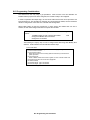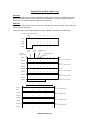
1
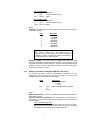
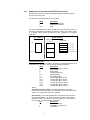
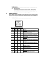
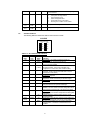
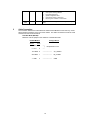
3100/3150 - PCX
MetOne Model PCX
Master Module
Revision 1.1
USER MANUAL
November 1996
ProSoft Technology, Inc.
9801 Camino Media
Suite 105
Bakersfield, CA 93311
[email protected]
http://www.prosoft-technology.com
Product Revision History
06/15/96
Revision 1.0
Initial release of product
11/16/96
Revision 1.10
Modified product to allow up to 32 slaves per port.
i
Implementation Guide
Integration of the PCX module into a PLC or SLC application is easier the first time if a series of steps are
followed. In order to assist the first time users of our products in getting the PCX operational quickly, we
have come up with this step-by-step implementation guide.
a)
b)
Starting with one of the ladder logic programs provided on disk with the PCX complete the following
steps:
PLC 5
PCX5
SLC 5/03
PCX503 (See Appendix for SLC programming tips)
Edit the ladder logic provided on disk as needed for the application
Verify rack and slot location in program
Modify ladder instruction addresses as needed
c)
Setup the Communication Configuration parameters (See Section 2)
Determine each port’s communication configuration requirements
d)
Setup the Polling List for each port (See Section 2)
Be sure to review register map of slave device to build most effective memory map
e)
Identify the jumper requirements (See Appendix)
f)
Make up the communication cables (See Section 5)
g)
Place processor into the run mode
h)
Monitor the data table for the Master Error Status values (See Section 2)
ii
Table of Contents
Revision History
Implementation Guide
i
ii
1 Product Specifications ..............................................................................................................1
2 PCX Theoretical Operation.......................................................................................................1
2.1 Block Transferring Data to the Module ...............................................................................2
2.1.1 Communications Configuration [ BTW Block ID 255 ] ..................................................2
2.1.2 Writing Control Block to Module[ BTW Block ID 0 and 1 ]............................................3
2.2 Block Transferring data from the module............................................................................4
2.2.1 Reading Data from the Module[ BTR Block ID 0 and 25 ].............................................5
3 Protocol Commands .................................................................................................................7
3.1 PCX Commands ................................................................................................................7
3.1.1 128 to 191 - Counter Select .........................................................................................7
3.1.2 C - Clear Buffer ...........................................................................................................7
3.1.3 d - Start Counting (Counter controlled )........................................................................7
3.1.4 A - Send Record ..........................................................................................................8
4 Hardware Diagnostics...............................................................................................................8
4.1 3100 PLC Platform.............................................................................................................8
4.2 3150 SLC Platform.............................................................................................................9
5 Cable Connection ...................................................................................................................10
Appendix
Support, Service and Warranty
Jumper Configurations
SLC Programming Considerations
Example Ladder Logic
PLC-5
SLC-5/03
1
Product Specifications
The 3100/3150-PCX (“MetOne PCX Master Module”) product family allows Allen-Bradley 1771
and 1746 I/O compatible processors to easily interface as a host with MetOne Particle Counting
Sensors.
The PCX product includes the following standard features:
• Two fully configurable serial ports, each capable of supporting the PCX Master
functionality
• Supports up to two(2) MetOne PCX 215W Counters per serial port
• Support movement of binary, integer, ASCII, and floating point data types
• Memory mapping will be pre-defined in the module to ease implementation in the ladder
program
• RS-485 connection from each port directly to PCX units
• Software configuration (From processor ladder logic)
Slave Addr
:
0 to 31 (module adds 128 automatically)
Command
:
Select command to be executed
Parity
:
None (fixed)
Stop Bit
:
1 (fixed)
Baud Rate
:
300 TO 38,400
RTS to TxD
:
50 ms (fixed)
Timeout
:
1 second
Polling Rate
:
1 second (fixed)
• Response time
The protocol drivers are written in Assembly and in a compiled higher level language.
As such, the interrupt capabilities of the hardware are fully utilized to minimize delays,
and to optimize the product's performance
• Supported PCX command codes:
Boot Sequence
C
Clear Buffer
d
Start Counting
On Line Sequence
A
Poll data while receiving ‘#’
Poll until get data, then extract data
• Operating Mode returned to ladder processor
• Error Codes returned to the ladder processor
2
PCX Theoretical Operation
Data transfers between the processor and the ProSoft Technology module occur using the Block
Transfer commands, in the case of the PLC, and M0/M1 data transfer commands, in the case of
the SLC. These commands transfer up to 64 physical registers per transfer. The logical data
length changes depending on the data transfer function.
The following discussion details the data structures used to transfer the different types of data
between the ProSoft Technology module and the processor. The term 'Block Transfer' is used
generically in the following discussion to depict the transfer of data blocks between the processor
and the ProSoft Technology module. Although a true Block Transfer function does not exist in the
SLC, we have implemented a pseudo-block transfer command in order to assure data integrity at
the block level. Examples of the PLC and SLC ladder logic are included in Appendix A.
In order for the ProSoft Technology module to function, the PLC must be in the
RUN mode, or in the REM RUN mode. If in any other mode (Fault/PGM), the
block transfers between the PLC and the module will stop, and communications
will halt until block transfers resume.
1
2.1
Block Transferring Data to the Module
Data transfer to the module from the processor is executed through the Block Transfer
Write function. The different types of data which are transferred require slightly different
data block structures, but the basic data structure is:
Word
0
1-63
Description
BTW Block ID code
Data
Although the full physical 64 words of the data buffer may not be used,
the BTW and M0 lengths must be configured for 64 words otherwise
module operation will be unpredictable.
Where:
BTW Block ID Code: A block identifier code between 0 and 255 in value. This code is
used by the ProSoft module to determine what to do with the data block. Valid codes
are:
BTW
Code
Description
0
Port 1 Control Block
1
Port 2 Control Block
255
Module Communication Configuration
Data: The data to be written to the module. The structure of the data is dependent on
the Block ID code. The following sections provide details on the different structures.
2.1.1
Communications Configuration [ BTW Block ID 255 ]
The ProSoft Technology firmware communication parameters must be
configured at least once when the card is first powered up, and any time
thereafter when the parameters must be changed.
On power up, the module enters into a logical loop waiting to receive
configuration data from the processor. While waiting, the module sets the
second word of the BTR buffer to 255, telling the processor that the module
must be configured before anything else will be done. The module will
continuously perform block transfers until the communications configuration
parameters block is received. Upon receipt, the module will begin execution of
the command list if present, or begin looking for the command list from the
processor.
Issueing a 255 Configuration command will cause the module
to act as if it had be powered down. The polling with all active
slaves will be initialized with a Clear Buffer command (see
Section 3)
The configuration data block structure which must be transferred from the
processor to the module is as follows:
BTW Block ID 255
Word
0
1-10
11-20
BTW
Buffer
0
Data
Word
Description
BTW Block ID = 255
Port 1 Configuration parameters
Port 2 Configuration parameters
Description
Block ID Header = 255
2
Port 1 Configuration
1
N[ ]:0
Baud Rate
2
N[ ]:1
Number of Slaves on port
3-10
N[ ]:2-9
Spare
Port 2 Configuration
11
N[ ]:10
Baud Rate
12
N[ ]:11
Number of Slaves on port
13-20 N[ ]:12-19 Spare
Where:
Baud Rate: The baud rate at which the module is to operate. The baud rate is
configured as follows:
Value
0
1
2
3
4
5
6
7
Baud Rate
300 Baud
600 Baud
1200 Baud
2400 Baud
4800 Baud
9600 Baud
19200 Baud
38400 Baud
The module’s two ports are limited to an upper baud rate of
either 19200 or 38400 baud.
The module cannot be
configured with one port at 19200 and the other at 38400. If
an attempt is made to configure the module in this fashion, a
Port Configuration Error will be returned.
Number of Slaves: The User is able to configure the number of slaves
(counters) which will be connected to the PCX module. This parameter is used
to optimize the module’s polling scheme (ie., limit the search for addresses) and
to layout the memory map for data being returned to the module. Valid values
for this entry is between 0 and 32.
2.1.2
Writing Control Block to Module[ BTW Block ID 0 and 1 ]
The ProSoft Technology firmware communication parameters must be
configured at least once when the card is first powered up, and any time
thereafter when the parameters must be changed.
Word
0
1-32
N[ ]:0
to
N[ ]:31
Description
BTW Block ID Number
0 - Port 1
1 - Port 2
Slave Poll Enable/Counter Address
Where:
BTW Block ID Number: This value determines which port the Control Block
will be used to control.
Slave Poll Enable/Counter Address: This field consists of a high byte and a
low byte entry. The high byte is the Slave Poll Enable and the low byte is the
Counter Address.
Slave Poll Enable (High Byte)
Entering a one (1) in this field will enable the slave to be polled.
Placing a zero in this field will cause the polling to be halted. Enabling
and disabling can be performed dynamically if desired.
3
Counter Address (Low Byte)
The value entered here will be added to 128 when the Counter Select
Command is issued (See Section 3). Counter addressing starts at 0
Slave Poll Enable/Counter Addresses
0
1
2
3
4
5
6
7
8
9
256
257
0
0
0
0
0
0
0
0
N9:10
0
0
0
0
0
0
0
0
0
0
N9:20
0
0
0
0
0
0
0
0
0
0
N9:30
0
0
0
0
0
0
0
0
0
0
N9:0
Port #1 Write Block to PCX Module (Addressing used in Example
ladder logic)
2.2
Block Transferring data from the module
When the Master port driver reads data from a slave, the resulting data is placed into the
ProSoft module’s data space. This Module Data space is then transferred to the
PLC/SLC.
The transfer of data from the ProSoft Technology module to the processor is executed
through the Block Transfer Read function. The data structure for the block transfer is
predefine and detailed below.
Although the full physical 64 words of the data buffer may not
be used, the BTR and M1 lengths must be configured for a
length of 64 words, otherwise module operation will be
unpredictable
The ladder logic must be programmed to look at the BTR buffer, decode several words,
and then take action. The BTR buffer definition is:
Word
0
1
2-62
Description
BTR Block ID
BTW Block ID
Data
Where:
BTR Block ID Number: The ladder logic uses this value to determine the
contents of the data portion of the BTR buffer. With some conditional testing in
ladder logic, the data from the module can be placed into the PLC/SLC data
table.
BTW Block ID Number: The module returns this value to the processor to be
used to enable the movement of the Slave Poll Enable/Counter Address blocks
(0 and 1) to the module.
Data: The contents of the module’s Register Data space containig the status
and results of the polling of the slaves. The values will be 16 bit register values
and floating point values, and should be placed into integer files. Note that the
user application ladder logic controls the placement and use of the data
registers.
4
2.2.1
Reading Data from the Module[ BTR Block ID 0 and 25 ]
The data moved from the module to the ladder program is determined by the
layout of the memory map.
The structure of the read data block s is as follows:
Word
0
1
2-51
Description
BTR Block ID Number
BTW Block ID Number
Data
In order to understand the movement of data from the module to the PLC, it is
important to understand the building of the memory map in the module. Below
is a diagram which shows the structure in the module for an example
application.
PLC Memory
Module Memory
Block Transfer
(50 words / blk)
N10:0
Counter Data
Port 1 - Cntr 1
Port 1 - Cntr 2
Port 2 - Cntr 1
Port 2 - Cntr 2
N10:100
System Information
Counter Data Structure
The response data from the counters is returned in a contigous data block of 20
words to the PLC data table. The structure of the data is as follows:
Word
Description
0
‘Send Data’ response counter
1
Device Status
2
Polling Stage
3
Communication Error
4-5
Sampling Period
6-7
Flow Rate (ml/min)
8-9
Concentration @ 2.0 micron
10-11
Concentration @ 4.0 micron
12-13
Concentration @ 5.0 micron
14-15
Concentration @ 10.0 micron
16-17
Concentration @ 15.0 micron
18-19
Concentration @ 20.0 micron
Where:
‘Send Data’ response counter: This value represents a 0 to 32767
counter which increments each time a new data record is received from the
counter. The counter will rollover to 0 at 32768.
Device Status: This is a bit mapped value returned from the Counter as
part of the data packet. The value returned from the Counter is masked
with 0xdf in order to turn off the ‘F’ (the ‘F’ bit is always a 1 when returned
from Counter). The status bit map is as follows:
Bit
Description
0
Calibrate Mode Fail
1
Low Battery or Wait (CNC)
2
Count Alarm
5
3
4
5
6
7
Model 231 Home fail or Low-high fluid
Analog Alarms or Fill
Masked out by PCX module
Unused or Air Flow alarm
Always 0
Polling Stage: Indicates the polling stage which the PCX module has
reached when communicating with a Counter. The value of the stages are
as follows (See Section 3 for command explanations):
Value
0
1
2
Description
Clear Buffer (C)
Start Counter (d)
Send Record (A)
Communication Error: A non-zero number indicates the type of
communciation error which is occuring with a Counter. This value is not
latched and will therefore clear to 0 on the first successfull
communciations. The values which can be expected in this field are:
Value
0
1
3
8
254
255
Description
All ok
Low Flow (0 flow) forces conc values to 0
Error in response
Timeout with Counter
Checksum error in response
TX Fail (Verify RTS to CTS jumper)
Sampling Period: Data retuned from Counter. This value is entered in the
Counter when the unit is configured for the application
Flow Rate: The Flow rate is expected to be read from the instrument as the
Analog Input AN0. The value read from the Counter is returrne in this field.
The value returned is expected to be in the 100ml/min range.
Concentration @ X micron: This is the calculated result determined by
the PCX module by the following equation:
( particle count) / ( ( period / 60 ) * flow rate )
System Information Data Structure
The module returns product information at the end of the counter data block.
The structure of the data is as follows:
Word
Description
0-1
Product Name (ASCII)
2-3
Revision (ASCII)
4-5
Operating System Rev(ASCII)
6-7
Production Run Number (ASCII)
Product Name: These two words represent the product name of the
module in an ASCII representation. In the case of the PCX product, the
letters ‘ PCX ‘ should be displayed when placing the programming software
in the ASCII data representation mode.
Revision : These two words represent the product revision level of the
firmware in an ASCII representation. An example of the data displayed
would be ‘1.00’ when placing the programming software in the ASCII data
representation mode.
6
Operating System Revision : These two words represent the module’s
internal operating system revision level in an ASCII representation.
Production Run Number: This number represents the ‘batch’ number that
your particular chip belongs to in an ASCII representation.
Counter
Status
Polling
Stage
Communication
Status
‘Send Data’
response counter
Begin Floating Point
Data
N10:0
6
0
2
0 16382
0
0
0
0
0
N10:10
0
0
0
0
0
0
0
0
0
0
N10:20
8
0
2
0 16382
0
0
0
0
0
N10:30
0
0
0
0
0
0
0
0
0
0
N10:40
8
0
2
0 16382
0
0
0
0
0
N10:50
0
0
0
0
0
0
0
0
0
0
N10:60
8
0
2
0 16382
0
0
0
0
0
N10:70
0
0
0
0
0
0
0
0
0
0
N10:80
PC
X
1.
0 0
08
01
0
0
0
Port 1
Slave #1 - Response/Status
Port 1
Slave #2 - Response Status
Port 2
Slave #1 - Response Status
Port 2
Slave #2 - Response Status
0 Product Information Block
Read Data Block from PCX Module
3
Protocol Commands
The ProSoft Technology PCX module Master driver supports several commands from the PCX
Command set.
3.1
PCX Commands
The PCX module supports a command subset of the Protocol Specification consisting
primarily of the commands required to intialize and read data from several units. The
following sections detail the different commands supported by the module.
Counter Select
Prior to any one of the commands outlined in 3.1.2 through 3.1.4 a Counter Select
command must be sent.
3.1.1
128 to 191 - Counter Select
Functions as a slave address select. The counter are configured as address 0
to 63. The counter which matches (+128) the Counter Select command will
respond to subsequence commands, until a new Counter Select value is
transmitted.
Power-Up Commands
During the initial polling of a slave, either after power up or after being offline, the PCX
module will issue a series of initialization commands.
3.1.2
C - Clear Buffer
Clears the rotating buffer in the Met One unit. This command is issued prior to
any other command to put the communications at a known state.
3.1.3
d - Start Counting (Counter controlled )
Allows the counter to begin counting and control the count cycle based on the
front panel setting for the period (sample time).
7
Polling Commands
During the regular polling of the slaves, the module will issue a command to each slave.
3.1.4
A - Send Record
Commands the unit to send the next record in the buffer. When the rotating
buffer is empty, the ‘#’ character is sent by the unit. If no count cycles have
been completed since the counter was turned on, then the ‘#’ is also sent. No
record is sent until the current count cycle is completed.
4
Hardware Diagnostics
Several hardware diagnostics capabilities have been implemented using the LED indicator lights
on the front of the module. The following sections explain the meaning of the individual LEDs for
both the PLC and the SLC platforms.
4.1
3100 PLC Platform
The following table documents the LEDs for the 3100-PCX module.
ProSoft CIM
Card
ACTIVE
CFG
ERR1
TXD1
RXD1
¡¡
¡¡
¡¡
¡¡
¡¡
FLT
BPLN
ERR2
TXD2
RXD2
Table 4.1 : PLC Platform LED Indication
ProSoft
CIM
ACT
A-B
DB/B
ACT
Color
Green
Status
Blink
(Fast)
On
Blink
( 1/Sec)
Off
FLT
FLT
Red
Off
On
CFG
DH485
Green
Off
Blink
On
BPLN
BTLO
Red
Off
On
ERR1
ERR2
LED1
LED2
Amber
Off
8
Indication
Normal state : The module is operating normally and
successfully Block Transferring with the PLC
The module is receiving power from the backplane, but
there may be some other problem
Indicates the module has somehow entered the Basic
Programming Mode. Verify jumper JW4 (DB/B only)
configuration. If all are correct, then contact the factory
The module is attempting to Block Transfer with the
PLC and has failed. The PLC may be in the PGM mode
or may be faulted
Normal State : No system problems are detected during
background diagnostics
A system problem was detected during background
diagnostics. Please contact factory for technical support
Normal state : No configuration related activity is
occurring at this time
This light blinks every time a Module Configuration block
(ID = 255) is received from the processor ladder logic
The light is on continuously whenever a configuration
error is detected. The error could be in the Port
Configuration data or in the System Configuration data.
See Section 4 for details
Normal State : When this light is off and the ACT light
is blinking quickly, the module is actively Block
Transferring data with the PLC
Indicates that Block Transfers between the PLC and the
module have failed.( Not activated in the initial release of
the product)
Normal State : When the error LED is off and the related
port is actively transferring data, there are no
communication errors
Blink
Periodic communication errors are occurring during data
communications.
This LED will stay on under several conditions:
•
CTS input is not being satisfied
•
Port Configuration Error
•
System Configuration Error
•
Unsuccessful comm on PCX slave
•
Recurring error condition on PCX master
On
Tx1
Tx2
Rx1
Rx2
4.2
PT1X
PT2X
PT1R
PT2R
Green
Blink
The port is transmitting data.
Green
Blink
The port is receiving data
3150 SLC Platform
The following table documents the LEDs for the 3150-PCX module.
3150-PCX
COMMUNICATIONS
ACT
FAULT
CFG
BPLN
PRT1
ERR1
PRT2
ERR2
Table 4.2 : SLC Platform LED Indication
LED
Name
ACT
Color
Green
Status
Blink
(Fast)
On
Blink
( 1/Sec)
Off
FLT
Red
Off
On
CFG
Green
Off
Blink
On
BPLN
Red
Off
On
ERR1
ERR2
Amber
Off
Blink
Indication
Normal state : The module is operating normally and
successfully Block Transferring with the SLC
The module is receiving power from the backplane, but there
may be some other problem
Indicates the module has somehow entered the Basic
Programming Mode. Verify jumper JW3 (BAS only)
configuration. If all are correct, then contact the factory
The module is attempting to Block Transfer with the SLC and
has failed. The SLC may be in the PGM mode or may be
faulted (Not in initial release)
Normal State : No system problems are detected during
background diagnostics
A system problem was detected during background
diagnostics. Please contact factory for technical support
Normal state : No configuration related activity is occurring at
this time
This light blinks every time a Module Configuration block (ID =
255) is received from the processor ladder logic
The light is on continuously whenever a configuration error is
detected. The error could be in the Port Configuration data or
in the System Configuration data. See Section 4 for details
Normal State : When this light is off and the ACT light is
blinking quickly, the module is actively Block Transferring data
with the SLC
Indicates that Block Transfers between the SLC and the
module have failed
Normal State : When the error LED is off and the related port
is actively transferring data, there are no communication errors
Periodic communication errors are occurring during data
communications. See Section 4 to determine the error
condition
9
On
TxRx1
TxRx2
5
Green
Blink
This LED will stay on under several conditions:
•
CTS input is not being satisfied
•
Port Configuration Error
•
System Configuration Error
•
Unsuccessful comm on PCX slave
•
Recurring error condition on PCX master
The port is communicating, either transmitting or receiving
data
Cable Connection
The connection between the 3100/3150-PCX module and the MetOne counter unit is by an RS485 to the DB connections on the front of the module. The cable connections for both the 3100
and the 3150 units are shown below:
Two Wire Mode (RS-485):
Please be sure the jumper on the module is in the RS-485 mode.
ProSoft Module
25-Pin
9-Pin
4 RTS
7
Foreign Device
---|
5 CTS
8
Jumper RTS to CTS
----
14 TxRxD+ 9
--------------------
A(+) TxRxD+
25 TxRxD- 1
--------------------
B(-) TxRxD-
7 GND
--------------------
GND
5
10
Support, Service and Warranty
Technical Support
ProSoft Technology survives on its ability to provide meaningful support to its
customers. Should any questions or problems arise, please feel free to contact us at:
Factory/Technical Support
ProSoft Technology, Inc.
9801 Camino Media, Suite 105
Bakersfield, CA 93311
(661) 664-7208
(800) 326-7066
(661) 664-7233 (fax)
E-mail address: [email protected]
Before calling for support, please prepare yourself for the call. In order to provide the
best and quickest support possible, we will most likely ask for the following information
(you may wish to fax it to us prior to calling):
1.
2.
3.
4.
5.
Product Version Number
Configuration Information
Communication Configuration
Jumper positions
System hierarchy
Physical connection information
RS-232, 422 or 485
Cable configuration
Module Operation
Block Transfers operation
LED patterns
An after-hours answering system (on the Bakersfield number) allows pager access to
one of our qualified technical and/or application support engineers at any time to answer
the questions that are important to you.
Module Service and Repair
The PCX card is an electronic product, designed and manufactured to function under
somewhat adverse conditions. As with any product, through age, misapplication, or any
one of many possible problems, the card may require repair.
When purchased from ProSoft Technology, the module has a one year parts and labor
warranty according to the limits specified in the warranty. Replacement and/or returns
should be directed to the distributor from whom the product was purchased. If you need
to return the card for repair, it is first necessary to obtain an RMA number from ProSoft
Technology. Please call the factory for this number and display the number prominently
on the outside of the shipping carton used to return the card.
General Warranty Policy
ProSoft Technology, Inc. (Hereinafter referred to as ProSoft) warrants that the Product
shall conform to and perform in accordance with published technical specifications and
the accompanying written materials, and shall be free of defects in materials and
workmanship, for the period of time herein indicated, such warranty period commencing
upon receipt of the Product.
This warranty is limited to the repair and/or replacement, at ProSoft's election, of
defective or non-conforming Product, and ProSoft shall not be responsible for the failure
of the Product to perform specified functions, or any other non-conformance caused by
or attributable to: (a) any misapplication of misuse of the Product; (b) failure of Customer
to adhere to any of ProSoft's specifications or instructions; (c) neglect of, abuse of, or
accident to, the Product; or (d) any associated or complementary equipment or software
not furnished by ProSoft.
Support, Service and Warranty
Limited warranty service may be obtained by delivering the Product to ProSoft and
providing proof of purchase or receipt date. Customer agrees to insure the Product or
assume the risk of loss or damage in transit, to prepay shipping charges to ProSoft, and
to use the original shipping container or equivalent. Contact ProSoft Customer Service
for further information.
Limitation of Liability
EXCEPT AS EXPRESSLY PROVIDED HEREIN, PROSOFT MAKES NO WARRANT OF
ANY KIND, EXPRESSED OR IMPLIED, WITH RESPECT TO ANY EQUIPMENT,
PARTS OR SERVICES PROVIDED PURSUANT TO THIS AGREEMENT, INCLUDING
BUT NOT LIMITED TO THE IMPLIED WARRANTIES OF MERCHANT ABILITY AND
FITNESS FOR A PARTICULAR PURPOSE. NEITHER PROSOFT OR ITS DEALER
SHALL BE LIABLE FOR ANY OTHER DAMAGES, INCLUDING BUT NOT LIMITED TO
DIRECT, INDIRECT, INCIDENTAL, SPECIAL OR CONSEQUENTIAL DAMAGES,
WHETHER IN AN ACTION IN CONTRACT OR TORT (INCLUDING NEGLIGENCE AND
STRICT LIABILITY), SUCH AS, BUT NOT LIMITED TO, LOSS OF ANTICIPATED
PROFITS OR BENEFITS RESULTING FROM, OR ARISING OUT OF, OR IN
CONNECTION WITH THE USE OR FURNISHING OF EQUIPMENT, PARTS OR
SERVICES HEREUNDER OR THE PERFORMANCE, USE OR INABILITY TO USE THE
SAME, EVEN IF PROSOFT OR ITS DEALER'S TOTAL LIABILITY EXCEED THE PRICE
PAID FOR THE PRODUCT.
Where directed by State Law, some of the above exclusions or limitations may not be
applicable in some states. This warranty provides specific legal rights; other rights that
vary from state to state may also exist. This warranty shall not be applicable to the
extent that any provisions of this warranty is prohibited by any Federal, State or
Municipal Law that cannot be preempted.
Hardware Product Warranty Details
Warranty Period : ProSoft warranties hardware product for a period of one (1) year.
Warranty Procedure : Upon return of the hardware Product ProSoft will, at its option,
repair or replace Product at no additional charge, freight prepaid, except as set forth
below. Repair parts and replacement Product will be furnished on an exchange basis
and will be either reconditioned or new. All replaced Product and parts become the
property of ProSoft. If ProSoft determines that the Product is not under warranty, it will,
at the Customer's option, repair the Product using current ProSoft standard rates for
parts and labor, and return the Product freight collect.
Support, Service and Warranty
Jumper Configurations
Hardware Overview
When purchasing the PCX product, there are two choices. These choices are as follows:
ProSoft Cat Num
PLC
SLC
3100
3150
Description
Module provided by ProSoft
When purchasing the module from ProSoft Technology, many of the jumper
configurations will have been factory set. When purchasing the firmware from ProSoft
Technology and the Allen-Bradley module from another source, particular attention must
be paid to hardware configuration.
Module Jumper Configurations
The following section details the available jumper configurations for the 1771 and 1746
platform solutions. As needed, differences between the module based solutions and the
firmware based solutions are highlighted.
3100 for the 1771 Platform
Following are the jumper positions for the ProSoft Technology 3100-PCX
module:
Jumper
JW1
JW2
JW3
JW4
JW5
JW6
JW7
JW8
JW9
3100
N/A
N/A
N/A
Not Used
8 Pt
Not Used
Enabled
As Needed
As Needed
JW5
Backplane 8/16 point
The module should be operated in the 8 pt mode only.
8 Point
JW7
Battery Enable / Disable
Enabled
This jumper should be placed in the Enabled position when the module
is powered up. Although not critical to the operation of the module,
this will back up some data registers in the module during a power
failure or reset.
JW8/9
RS Configuration for Port 1 and 2
See options on module
The default from factory is RS-232, but all options are supported by the
PCX firmware
3150 for the 1746 Platform
Following are the jumper positions for the ProSoft Technology 3150-PCX
module:
Jumper
JW1
JW2
JW3
JW4
JW1/2
3150-PCX
As Needed
As Needed
N/A
N/A
RS configuration for port 1 and 2
See Appendix C
The default from factory is RS-232, but all options are supported by the
PCX firmware
Jumper Configurations
Communication Port
Jumper Settings for 3150 Modules - JW1 & JW2
RS-232
RS-422
4-wire
RS-485
2-wire
RS-232
RS-422
4-wire
RS-485
2-wire
Jumper Configurations
SLC Programming Considerations
The 3150-PCX is also very easy to get operational. After the lPCX cover and firmware are
installed and the jumpers have been configured, the module is ready to be configured.
In order to implement the sample logic, the user must make sure that the correct processor and
rack size match up. Also, should it be necessary to re-locate the PCX module, the user should be
certain to configure the correct slot as a 1746-BAS 5/02 Configuration.
When initially setting up the SLC program file, or when moving the module from one slot to
another, the user must configure the slot to accept the PCX module.
It is important that the slot containing the ProSoft module be configured as
follows:
1746-BAS module or enter 13106 for the module
code
Configure the M0/M1 files for 64 words
Configure I/O for 8 words
The following is a step by step on how to configure these files using Allen-Bradley APS
software. ICOM software users should follow similar steps.
From the Main Menu:
1) Select the correct processor program and F3 for Offline programming
2) F1 for Processor Functions
3) F1 for Change Processor
Modify the processor here if necessary (Note the PCX will only work with 5/02 or
greater processors
4) F5 for Configure I/O
Select 1746-BAS module for SLC 5/02 or greater, or enter 13106 for module code
5) F9 for SPIO Config when the correct slot is highlighted
6) F5 Advanced Setup
7) F5 for M0 file length - type in 64 and Enter
8) F6 for M1 file length - type in 64 and Enter
Esc out and save configuration
SLC Programming Considerations
Example PLC and SLC Ladder Logic
Overview
The following ladder logic provides an example for the ladder logic necessary to integrate the 3100-PCX
and the 3150-PCX modules into their respective processor platforms. This logic can be incorporated
directly as is, or if desired modified as needed for the application.
Data Files
The examples use the same memory map for both of the platforms, with the exception of the actual block
transfer data and control files.
The memory map for the example application has been detailed in the attached data table listing.
Slave Poll Enable/Counter Addresses
0
1
2
3
4
5
6
7
8
9
256
257
0
0
0
0
0
0
0
0
N9:10
0
0
0
0
0
0
0
0
0
0
N9:20
0
0
0
0
0
0
0
0
0
0
N9:30
0
0
0
0
0
0
0
0
0
0
N9:0
Counter
Status
Polling
Stage
Communication
Status
‘Send Data’
response counter
Begin Floating Point
Data
N10:0
6
0
2
0 16382
0
0
0
0
0
N10:10
0
0
0
0
0
0
0
0
0
0
N10:20
8
0
2
0 16382
0
0
0
0
0
N10:30
0
0
0
0
0
0
0
0
0
0
N10:40
8
0
2
0 16382
0
0
0
0
0
N10:50
0
0
0
0
0
0
0
0
0
0
N10:60
8
0
2
0 16382
0
0
0
0
0
N10:70
0
0
0
0
0
0
0
0
0
0
N10:80
PC
X
1.
0 0
08
01
0
0
0
0
1
2
3
4
F11:0
0
0
0
0
0
F11:5
0
0
0
0
0
F11:10
0
0
0
0
0
F11:15
0
0
0
0
0
F11:20
0
0
0
0
0
F11:25
0
0
0
0
0
F11:30
0
0
0
0
0
F11:35
0
0
0
0
0
Example Ladder Logic
Port 1
Slave #1 - Response/Status
Port 1
Slave #2 - Response Status
Port 2
Slave #1 - Response Status
Port 2
Slave #2 - Response Status
0 Product Information Block
Port 1
Slave #1 - Response/Status
Port 1
Slave #2 - Response/Status
Port 2
Slave #1 - Response/Status
Port 2
Slave #2 - Response/Status