1
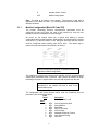
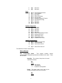
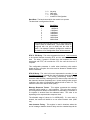
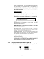
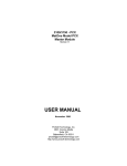
Corporate Office 1675 Chester Ave. Fourth Floor Bakersfield, CA 93301 (661) 716-5100 Phone (661) 716-5101 Fax Southeast US Sales Office E-mail: [email protected] Tomball, TX (281) 370-6297 Phone (281) 370-5932 Fax 3100/3101- LNG Revision 1.0 3150/3151- LNG Revision 1.0 August 1995 Landis & Gyr Communication Module ______________________________________________________ USER MANUAL Please Read This Notice Successful application of the LNG card requires a reasonable working knowledge of the Allen-Bradley PLC or SLC hardware and the application in which the combination is to be used. For this reason, it is important that those responsible for implementing the LNG product satisfy themselves that the combination will meet the needs of the application without exposing personnel or equipment to unsafe or inappropriate working conditions. This manual is provided to assist the user. Every attempt has been made to assure that the information provided is accurate and a true reflection of the product's installation requirements. In order to assure a complete understanding of the operation of the product, the user should read all applicable Allen-Bradley documentation on the operation of the A-B hardware. Under no conditions will ProSoft Technology, Inc. be responsible or liable for indirect or consequential damages resulting from the use or application of the LNG product. Reproduction of the contents of this manual, in whole or in part, without written permission from ProSoft Technology, Inc. is prohibited. Information in this manual is subject to change without notice and does not represent a commitment on the part of ProSoft Technology, Inc. Improvements and/or changes in this manual or the product may be made at any time. These changes will be made periodically to correct technical inaccuracies or typographical errors. ProSoft Technology, Inc. 1995, 1996, 1997 The Telegyr protocol specification has been provided by Landis & Gyr Energy Managememt, Inc. TABLE OF CONTENTS I II III IV V Card Overview .............................................................................................................. 1 Programming Considerations ........................................................................................ 3 2.1 3100/3101-LNG Overview ............................................................................. 3 2.2 3150/3151-LNG Overview ............................................................................. 3 2.2.1 SLC Processor I/O Configuration ...................................................... 3 2.3 Ladder Logic Considerations ......................................................................... 4 2.3.1 Operational Overview........................................................................ 4 2.4 Memory Organization .................................................................................... 4 2.4.1 Moving PLC/SLC Data to the Module ................................................ 4 2.4.2 Moving Module Data to the PLC/SLC ................................................ 5 Theoretical Operation.................................................................................................... 7 3.1 Transferring Data to the Module .................................................................... 7 3.1.1 Module Configuration [Block ID Code 255] ........................................ 8 3.1.2 Moving Data to the Module [Block ID Codes 0-8]............................... 11 3.2 Reading Data from the Module ...................................................................... 12 3.2.1 Analog Output Data [ BTR Block ID 0 ].............................................. 13 3.2.2 Digital Output Data [ BTR Block ID 1 ] ............................................... 13 3.2.3 Accumulator Preset Data [ BTR Block ID 2 ]...................................... 14 3.2.4 Pulse Commands [ BTR Block ID 3 and 4] ........................................ 14 3.2.5 SBO Commands [ BTR Block ID 5 ] .................................................. 15 3.2.6 Slave Error Code Table..................................................................... 15 3.2.7 Error Status Codes............................................................................ 17 Landis & Gyr Protocol Details........................................................................................ 19 4.1 Analog Change Report - 0 ............................................................................. 19 4.2 Analog Force Report - 1 ................................................................................ 19 4.3 Analog Group Change Report - 2................................................................... 19 4.4 Analog Group Force Report - 3...................................................................... 19 4.5 ADC Reference Force Report - 5 ................................................................... 19 4.6 Indication Change Report - 6 ......................................................................... 19 4.7 Indication Change Report - 7 ......................................................................... 19 4.8 Digital Input Force Report - 11 ....................................................................... 19 4.9 Accumulator Change Report - 12................................................................... 19 4.10 Accumulator Force Report - 13 ...................................................................... 20 4.11 Analog Output - 20 ........................................................................................ 20 4.12 SBO Select - 21............................................................................................. 20 4.13 SBO Operate - 22.......................................................................................... 20 4.14 Digital Output - 23.......................................................................................... 20 4.15 Accumulator Freeze - 24 ............................................................................... 20 4.16 Pulse Output - 25 .......................................................................................... 20 4.17 Pulse Train Output - 26 (Hold) ....................................................................... 20 4.18 Restart RTU - 30 ........................................................................................... 20 4.19 RTU Configuration - 31.................................................................................. 20 4.20 Analog Deadbands - 34 ................................................................................. 20 4.21 Analog Group Defines - 35 ............................................................................ 21 4.22 Accumulator Preset - 36 ................................................................................ 21 4.23 Continuation Request - 37 ............................................................................. 21 4.24 Repeat Last Message - 38............................................................................. 21 4.25 Firmware Configuration - 39 .......................................................................... 21 4.26 Exception Report - 63.................................................................................... 21 Hardware Diagnostics ................................................................................................... 22 5.1 3100 PLC Platform ........................................................................................ 22 5.2 3150 SLC Platform ........................................................................................ 23 Appendices Appendix A Support, Service and Warranty Appendix B Cable Connection Diagrams 3100 Module 3150 Module Appendix C 3100 Jumper diagrams 3150 Jumper diagrams Appendix D Product Revision History Appendix E Sample Ladder Logic Programs I Card Overview The 3100/3150-LNG Landis & Gyr product supports the L&G Telegyr RTU Protocol. The LNG product allows Allen-Bradley 1771 and 1746 I/O compatible processors to easily interface with host devices supporting the Landis & Gyr protocols. The product is available from ProSoft Technology as either a module or a firmware solution. The firmware solution allows standard Allen-Bradley 1771-DB/B and 1746-BAS modules to be used as hardware platforms. The LNG product includes the following standard features: General Specifications • Two fully configurable serial ports, each individually capable of supporting the Landis & Gyr Slave implementation of the protocol. • Software configuration (From processor ladder logic) Slave Addr : 1 to 255 Parity : None, odd, or even, Stop Bit: 1 or 2 Baud Rate : 300 TO 38,400 RTS to TxD : 0-65535 ms delay, 1 ms resolution RTS Off : 0-65535 ms delay, 1 ms resoluton • RS-232C handshaking for SCADA radio/modem applications • RS-422/RS-485 compatible for multidrop applications with up to 32 slaves per port • Error Status and Communication Statistics for each port returned to the ladder processor • Support for the storage and transfer of up to 4000 registers to the PLC and SLC data tables • Memory mapping is completely user definable through data table configuration • Response time The Modbus Master and Slave protocol drivers are written in Assembly and in a compiled higher level language. As such, the interrupt capabilities of the hardware are fully utilized to minimize delays, and to optimize the product's performance Landis & Gyr Slave Specifications • Landis & Gyr Telegyr protocol - Slave implementation • Binary Data Stream with CRC-16 Error Checking • Supported Function Codes: 0 Analog Change Report 1 Analog Force Report 2 Analog Group Change Report 1 3 5 6 7 11 12 13 20 21 22 23 24 25 26 30 31 33 34 35 36 37 38 39 63 • Analog Group Force Report ADC Reference Force Report Indication Change Report Indication Force Report Digital Input Force Report Accumulator Change Report Accumulator Force Report Analog Output SBO Select SBO Operate Digital Output Accumulator Freeze Pulse Output Pulse Train Output (Hold) Restart RTU RTU Configuration Time Bias Analog Deadbands Analog Group Define Accumulator Preset Continuation Request Repeat Last Message Firmware Configuration Exception Report Master Broadcast Addressing to Slaves ( Address 0 ) 2 II Programming Considerations The LNG product family is very easy to integrate into the Allen-Bradley platforms. In both the PLC and the SLC platforms, the addition of several simple ladder rungs and the configuration of several registers enables the module to operate as a very effective Landis & Gyr Slave protocol interface. To ease initial contact with the product we have included a demonstration ladder program in Appendix A. An electronic copy of the ladder logic is available on disk with each product purchase. The following discussion covers the example logic located in Appendix A in an overview fashion. In addition, an explanation is given on how to adjust the ladder logic for a different application. 2.1 3100/3101-LNG Overview Programming of the 3100-LNG is less complicated than our previous products for the PLC-5 environment. Once all of the jumpers have been setup and the chip installed, the module is ready to be configured and run. See Section 4 for details on configuring the module. In order to get the LNG operating with the example ladder logic only one modification should be necessary. The ladder logic BTR and BTW instructions may need to be modified to ensure that the Block Transfer instructions are set up for the correct slot address. 2.2 3150/3151-LNG Overview The 3150-LNG is also very easy to get operational. After the lens cover and firmware are installed and the jumpers have been configured, the module is ready to be configured. See Section 2 for details on configuring the module. In order to implement the sample logic, the user must make sure to perform the Processor Configuration function to be sure that the processor and rack size match the actual hardware. Also, should it be necessary to re-locate the LNG module, the user should be certain to configure the correct slot as a 1746-BAS 5/02 Configuration. 2.2.1 SLC Processor I/O Configuration When initially setting up the SLC program file, or when moving the module from one slot to another, the user must configure the slot to accept the LNG module. It is important that the slot containing the ProSoft module be configured as follows: - 1746-BAS module or enter 13106 for the module code - Configure the M0/M1 files for 64 words - Configure I/O for 8 words The following is a step by step on how to configure these files using AllenBradley APS software. ICOM software users should follow similar steps. From the Main Menu: 1) Select the correct processor program and F3 for Offline programming 2) F1 for Processor Functions 3) F1 for Change Processor Modify the processor here if necessary (Note the LNG will only work with 5/02 or greater processors 3 4) F5 for Configure I/O Select 1746-BAS module for SLC 5/02 or greater, or enter 13106 for module code 5) F9 for SPIO Config when the correct slot is highlighted 6) F5 Advanced Setup 7) F5 for M0 file length - type in 64 and Enter 8) F6 for M1 file length - type in 64 and Enter 9) Esc out and save configuration 2.3 Ladder Logic Considerations Those familiar with our 1100 family of products will observe that the ladder logic requirements for the LNG are substantially less. Much of the simplification of the ladder logic is due to: • • The module now controls and feeds the Block ID numbers to the ladder logic. All ladder logic associated with manipulating the Block ID number has been eliminated The Slave port now directs write commands to the module’s local memory. Previously write commands bypassed the module’s memory and were passed to the backplane. All logic associated with decoding these write commands have been eliminated from the ladder logic 2.3.1 Operational Overview On power up the ProSoft module moves a 255 into the BTR data file. This is a signal to the ladder logic that the module is ready to receive configuration data before proceeding any further. The ladder logic should move the Configuration Data Block into the BTW buffer (See Section 4) at this point. Once the Configuration Data is received, the module will begin transferring data to and from the processor depending upon how many Read and Write block counts have been configured. The data structure between the module and the processor for the L&G slave data is predefined and discussed in more detail in the following Section and in Section 4. 2.4 Memory Organization The movement of data to and from the module is performed through predefined data blocks. A set of blocks has been defined for writing to the module (for responses to Host read commands) and for reading from the module (for data written to the module by Host write commands). 2.4.1 Moving PLC/SLC Data to the Module Data movement to from the processor the the LNG module is coordinated by the module through the BTW Block ID (See Section 4 for details on the actual transfer process). The following ladder branch shows an example of the ladder logic moving Digital Input data to the module. DECODES WRITES | BLOCK ID 1 BLOCK | | | | +EQU------------+ +COP--------------+ | +-+EQUAL +-+COPY FILE +|-+ | |Src A M0:1.0| |Source #N10:50| | | | *| |Dest #M0:1.1| | | |Src B 1| |Length 50| | | | | +-----------------+ | | +---------------+ | 4 PLC/SLC Data Table Memory Move Data to Module PLC Data Addr N9:0 LNG Module Memory BTW Block ID 0 to 8 BTW Block ID 0 0 Analog Inputs N9:50 BTW Block ID 1 49 0 Analog Inputs N9:100 BTW Block ID 2 49 0 Analog Inputs N9:150 BTW Block ID 3 49 0 Analog Inputs 49 0 N9:200 BTW Block ID 4 Analog Inputs Respond to read requests from Landis & Gyr Host 49 0 N10:0 BTW Block ID 5 Analog Inputs N10:50 49 0 BTW Block ID 6 Digital Inputs N10100 49 0 BTW Block ID 7 Accumulator Counts 49 0 N10:150 BTW Block ID 8 Indicator Status Figure 3.1 : 49 Relationship between the PLC data table (in Appendix A example) and the LNG module memory types. 2.4.2 Moving Module Data to the PLC/SLC Data movement to from the processor the the LNG module is coordinated by the module through the BTW Block ID (See Section 4 for details on the actual transfer process). BT READ | DATA BLOCK | | ID = 1 | | +EQU------------+ +COP------------+ | +-+EQUAL +---+COPY FILE +-+ | |Src A M1:1.0| |Source #M1:1.2| | | | *| |Dest #N11:50| | | |Src B 1| |Length 50| | | | | +---------------+ | | +---------------+ | In this example, the BTR Block ID is 1, therefore the Digital Output Image is being transferred to the processor data table. 5 PLC/SLC Data Table Memory PLC Data Addr N11:0 Move Data from Module LNG Module Memory BTR Block ID 0 to 5 BTR Block ID 0 0 Analog Outputs N11:50 BTR Block ID 1 49 0 Digital Outputs N11:100 BTR Block ID 2 49 0 Accumulator Presets N11:150 BTR Block ID 3 Write requests from Landis & Gyr Host 49 0 Pulse Commands N11:200 BTR Block ID 4 49 0 Pulse Commands N11:250 BTR Block ID 5 49 0 SBO Commands 49 Figure 3.2 : Relationship between the PLC data table (in Appendix A example) and the LNG module memory types. 6 III Theoretical Operation Data transfers between the processor and the ProSoft Technology module occur using the Block Transfer commands, in the case of the PLC, and M0/M1 data transfer commands, in the case of the SLC. These commands transfer up to 64 physical registers per transfer. The logical data length changes depending on the data transfer function. The following discussion details the data structures used to transfer the different types of data between the ProSoft Technology module and the processor. The term 'Block Transfer' is used generically in the following discussion to depict the transfer of data blocks between the processor and the ProSoft Technology module. Although a true Block Transfer function does not exist in the SLC, we have implemented a pseudo-block transfer command in order to assure data integrity at the block level. Examples of the PLC and SLC ladder logic are included in Appendix A. In order for the ProSoft Technology module to function, the PLC must be in the RUN mode, or in the REM RUN mode. If in any other mode (Fault/PGM), the block transfers between the PLC and the module will stop, and communications will halt until block transfers resume. 3.1 Transferring Data to the Module Data transfer to the module from the processor is executed through the Block Transfer Write function and a data block paging scheme standard to all ProSoft products. The different types of data which are transferred require slightly different data block structures, but the basic data structure is: Word 0 1-63 Description BTW Block ID code Data In a PLC, the BTW length must be configured for 64 words, otherwise module operation will be unpredictable. BTW Block ID Code: A block identifier code between 0 and 255 received from the module during the BTR function (the 2nd word of the BTR contains the Block ID Code for the next BTW). See Section 4.2. ENCODES | BLOCK | | | | +MOV-----------+ | +----------------------+MOVE +-+ | |Source M1:1.1| | | | *| | | |Dest M0:1.0| | | | *| | | +--------------+ | This code is used by the ProSoft module to determine what to do with the data block. The Block ID codes have been preassigned the following meanings: Code 0-5 6 7 Description Analog Inputs Digital Inputs Accumulators 7 8 Indicator Points - Status 255 Module Configuration Data: The data to be written to the module. The structure of the data is dependent on the Block ID code. The following sections provide details on the different structures. 3.1.1 Module Configuration [Block ID Code 255] The ProSoft Technology firmware communication parameters must be configured at least once when the card is first powered up, and any time thereafter when the parameters must be changed. On power up, the module enters into a logical loop waiting to receive configuration data from the processor. While waiting, the module sets the second word (Word 1) of the BTR buffer to 255, telling the processor that the module must be configured before anything else will be done. The ladder logic to perform the data movement to the module is as follows: DECODES WRITES | BLOCK BLOCK | | | | +EQU------------+ +COP--------------+ | +-+EQUAL +++COPY FILE +-+ | |Src A M0:1.0|||Source #N7:0| | | | *|||Dest #M0:1.1| | | |Src B 255|||Length 50| | | | ||+-----------------+ | | +---------------+| USER CONFIG | | | DOWNLOAD | | | SELECT | | | B3 | | +---------(U)--------+ | 0 | The OTU on the User Config Bit is included to disable an application initiated configuration. The module will continuously perform block transfers until the communications configuration parameters block is received. Upon receipt, the module will begin executing the transfer of register data to service read requests from the host. Transferring the Communications Configuration Parameters to the module will force a reset of the communication ports. The configuration data block structure which must be transferred from the processor to the module is as follows: Data Word Description Block ID Header = 255 Port 1 0 N[]:0 Port Configuration Word 1 N[]:1 Slave Address 2 N[]:2 Baud Rate 3 N[]:3 RTS to TxD Delay 4 N[]:4 RTS off Delay 5 N[]:5 Message Response Timeout 6 N[]:6 Inter-character timing 7 N[]:7 Not Used 8 8 9 N[]:8 N[]:9 Not Used Not Used 10 11 12 13 14 15 16 17 18 19 N[]:10 N[]:11 N[]:12 N[]:13 N[]:14 N[]:15 N[]:16 N[]:17 N[]:18 N[]:19 Port Configuration Word Slave Address Baud Rate RTS to TxD Delay RTS off Delay Message Response Timeout Inter-character timing Not Used Not Used Not Used Port 2 System Configuration 20 N[]:20 Not Used 21 N[]:21 Not Used 22 N[]:22 Not Used 23 N[]:23 Not Used 24 N[]:24 Not Used 25 N[]:25 Block Transfer Delay Counter 26 N[]:25 Analog Input Count 27 N[]:25 Digital Input Count 28 N[]:25 Accumulator Count 29 N[]:25 Indication Point Count L&G RTU Configuration 30 N[]:30 Number of I/O Chassis 31 N[]:31 Chassis Number 32 N[]:32 Card Code for Slot 0 47 N[]:47 Card Code for Slot 15 The definitions for these values follows: Port 1 and Port 2 Port Configuration Word: This register contains several communication configuration parameters encoded into the word. These are as follows: Stop Bits: The number of stop bits to be used is defined as follows: Bits 13 12 0 0 0 1 1 x One stop bit Two stop bits Invalid Port Configuration Parity: The parity mode to be used by the module is defined by this word as follows: Bits 15 14 9 0 0 1 1 0 1 0 1 No parity Odd parity Even parity Invalid Port Configuration Baud Rate: The baud rate at which the module is to operate. The baud rate is configured as follows: Value 0 1 2 3 4 5 6 7 Baud Rate 300 Baud 600 Baud 1200 Baud 2400 Baud 4800 Baud 9600 Baud 19200 Baud 38400 Baud The module’s two ports are limited to an upper baud rate of either 19200 or 38400 baud. The module cannot be configured with one port at 19200 and the other at 38400. If an attempt is made to configure the module in this fashion, a Port Configuration Error will be returned. RTS To TXD Delay: This value represents the time in 1 ms increments to be inserted between asserting RTS, and the actual transmission of data. The delay, if greater in duration than the hardware time delay associated with CTS, will override the CTS line until the time-out is complete. This configurable parameter is useful when interfacing with modem based devices, or anytime line noise must be allowed to subside before data is transmitted. RTS Off Delay: The value in this word represents the number of 1 ms time delay increments inserted after the last character is transmitted and before RTS is dropped. The module automatically inserts a one character width Off Delay, assuring that RTS does not drop until after the last character has been completely sent. Unless working under unusual conditions, this value will normally be configured with a value of 0. The maximum value to be used is 65535 (0xffff). Message Response Timout: This register represents the message response timeout period in 1 ms increments. This is the time which a port configured as a Master will wait before re-transmitting a command if no response is received from the addressed slave. The value is set depending on the expected slave response times. The allowable range of values is 0 to 65535(0xffff). If a zero value is entered, the module will default to a one second timeout value (1000 ms). Inter-character Timing: This register is used in situations where the end of message character timeout delay must be extended beyond the 10 normal 3.5 character widths. The value entered represents the number of 1 ms intervals of ‘no transmission’ which will be counted prior to accepting a message. This parameter will be useful in satallite or packet radio installation where a data transmission may be split between two packets. Increasing this value beyond the system’s packet handling time will eliminate timeout errors. System Configuration Block Transfer Delay Counter: This value is used by the module to slow down the block transfer loading between the module and the processor. Excessive Block Transfers can slow down the response time of the LNG’s communication ports. This parameter has been provided to allow the Block Transfer timing to be determined on an application basis. A value of 0 is normally used at the factory and is recommended as a starting point. Analog Input Count: This value represents the number of Analog Input data points which will be transferred to the LNG module. The value selected can range from 0 to 50. Digital Input Count: This value represents the number of 16 bit Digital Input words which will be transferred to the LNG module. The value selected can range from 0 to 50. Accumulator Count: This value represents the number of Accumulator registers which will be transferred to the LNG module from the PLC/SLC hardware. The value selected can range from 0 to 50. Indication Point Count: This value represents the number of Contact Status Indication words (16 points per word) which will be transferred to the LNG module. The value selected can range from 0 to 50. L&G RTU Configuration Function Code 31 Configuration Data : The values in words 30 to 47 represent the configuration data necessary to satisfy the L&G Function Code 31 RTU Configuration read command. Please see the protocol document for valid values if this command will be used. 3.1.2 Moving Data to the Module [Block ID Codes 0-8] Writing register data to the ProSoft Technology module is a simple Block Transfer Write with Block ID codes from 0 to 8 followed by 50 words of data. The actual data that is transferred with each Block ID is predefined as follows: Code 0-5 6 7 8 Description Analog Inputs Digital Inputs Accumulators Indicator Points - Status 11 As an example of the ladder logic necessary to move the data to the module, the following will move the Digital Input image from N10:50 to N10:99 into the module whenever the Write Block ID (M0:1.0 in this example) is equal to 1. DECODES WRITES | BLOCK ID 1 BLOCK | | | | +EQU------------+ +COP--------------+ | +-+EQUAL +-+COPY FILE +|-+ | |Src A M0:1.0| |Source #N10:50| | | | *| |Dest #M0:1.1| | | |Src B 1| |Length 50| | | | | +-----------------+ | | +---------------+ | By paging the different data blocks into the module the processor can control the module data memory contents. 3.2 Reading Data from the Module The transfer of data from the ProSoft Technology module to the processor is executed through the Block Transfer Read function. Three basic different types of data are read from the module: • • Write Data [ Block ID 0 to 5 ] Configuration Request [ Block ID 255 ] The data structure for the block transfer depends on the type of block data. The following sections detail the different types of data. In a PLC, the BTR length must be configured for a length of 64 words, otherwise module operation will be unpredictable The ladder logic must be programmed to look at the BTR buffer, decode several words, and then take action. The BTR buffer definition is: Word 0 1 2-62 Description BTR Block ID Code BTW Block ID Code Data Where: BTR Block ID Code: A block identifier code between 0 and 5 received from the module during the BTR function. This code is used by the ProSoft module to determine what to do with the data block. The Block ID codes have been preassigned the following meanings: Code 0 1 2 3 4 5 255 Description Analog Outputs Digital Outputs Accumulator Presets Pulse commands Pulse commands SBO command & Module Status Module Configuration Request 12 BTW Block ID Code: The module returns this value to the processor to be used to enable the movement of BTW register data blocks to the module. The BTW Block ID number is developed by the module by simply scrolling through the available values (0 to 4) (See Section 4.1.1). Data: These registers contain the data corresponding to the data type defined by the BTR Block ID Code. These data values represent the values written to the module from the host through either Port 1 and/or Port 2. Note that the user application ladder logic controls the placement and use of the data registers when moving the values out of the Block Transfer buffers: BT READ | DATA BLOCK | | ID = 1 | | +EQU------------+ +COP------------+ | +-+EQUAL +---+COPY FILE +-+ | |Src A M1:1.0| |Source #M1:1.2| | | | *| |Dest #N11:50| | | |Src B 1| |Length 50| | | | | +---------------+ | | +---------------+ | In this example, the BTR Block ID is 1, therefore we are moving the Digital Output Image to the processor data table. 3.2.1 Analog Output Data [ BTR Block ID 0 ] This data block is only transferred to the processor on power-up and whenever a write command is received from the host. The 50 word block contains an image of the write data that has been received from the host. Important - On power up the table is cleared and transferred once to the processor - After power up, the block is only transferred to the processor after receiving a write command from the host The values will be 16 bit register values ranging from 0 to 4095, and should be placed into an integer file. Note that the user application ladder logic controls the placement and use of these values received. 3.2.2 Digital Output Data [ BTR Block ID 1 ] This data block is only transferred to the processor on power-up and whenever a write command is received from the host. The 50 word block contains an image of the write data that has been received from the host. Important - On power up the table is cleared and transferred once to the processor - After power up, the block is only transferred to the processor after receiving a write command from the host The values will be 16 bit Digital Output Images and can be placed into an Integer file or a Binary file. Note that the user application ladder logic controls the placement and use of these values received. 13 3.2.3 Accumulator Preset Data [ BTR Block ID 2 ] This data block is only transferred to the processor on power-up and whenever a write command is received from the host. The 50 word block contains an image of the write data that has been received from the host. Important - On power up each register in the table is set to 32767 and transferred once to the processor - After power up, the block is only transferred to the processor after receiving a write command from the host The values will be 16 bit values which can be transferred directly to Counter Preset registers or to an Integer file. Note that the user application ladder logic controls the placement and use of these values received. 3.2.4 Pulse Commands [ BTR Block ID 3 and 4] These data blocks are transferred to the processor on a continuous basis. Bits and register values within the blocks are toggles and set as the result of receiving writes from the host. Valid Pulse Points which can be addressed by the host will range from 0 to 8. Important - On power up each register in the table is set to 0 prior to being transferred to the processor - After power up, the blocks are transferred to the processor continuously. Ladder logic must be implemented to decode and implement the pulse functionality Note that the user application ladder logic fully controls the implementation of the pulse functionality. These BTR Blocks contain predefined data structures within the block to assist the user in implementing the pulse commands. The structure for the two blocks is as follows: Block ID 3 Data 0-9 Pulse - 10 ms raise 10-19 Pulse - 10 ms lower 20-29 Pulse - 100 ms raise 30-39 Pulse - 100 ms lower 40-49 Pulse - 1 s raise Block ID 4 Data 0-9 Pulse - 1 s lower 10-19 Pulse - 10 s raise 20-29 Pulse - 10 s lower 30-39 Not Used 40-49 Not Used Within each of these 10 word structures, the following data can be extracted in ladder logic: Word 0 Description Pulse Cmd Active Flags 14 1-9 Pulse Duration Pulse Cmd Active Flag: Bits 0 to 8 in this word are used to indicate that a Pulse Command has been received from the hast addressed to Pulse Point 0 to 8. The time base commanded by the host determines were the data will be located in BTR Block ID 3 and 4. Pulse Duration: This value represents the duration in the selected time base which has been commanded by the host. 3.2.5 SBO Commands [ BTR Block ID 5 ] The SBO Command block is transferred to the processor on a continuous basis. Ladder logic decoding must be provided to implement the SBO commands received from the host. Important - On power up each register in the table is set to 0 prior to being transferred to the processor - After power up, the blocks are transferred to the processor continuously. Ladder logic must be implemented to decode and implement the pulse functionality - Only one SBO command will be processed per command sequence from the host. Please assure that only one command is sent at a time. The BTR Block contain a predefined data structure within the block to assist the user in implementing the SBO commands. The structure is as follows: Block ID 5 Data 0 SBO Active Flag 1 SBO Bit Address 2 SBO Operation 3 SBO Duration 4-29 Not Used 30-49 See Section 4.2.6 SBO Active Flag: This field will contain a 1 when an SBO Command Select/Operate sequence has been successfullly received from the Host. It is used as the primary ladder logic decode to enable the use of the remaining SBO values. SBO Bit Address : This value represents the Bit Address which has been addressed by the Host. This value can be used to indirectly address a Bit file in the PLC. SBO Operation : This value will contain a 1 to issue a Close command and a 0 to issue a Trip Command. SBO Duration : This value will containg the duration value received from the host as part of the SBO command. The time base is user definable through the selection of Timers in the processor. 3.2.6 Slave Error Code Table 15 The LNG Module monitors the status of all Slave port commands. This status is communicated to the processor in the form of a Slave Error Code Table. The Slave Error Code Table is initialized to zero on power up, and every time the module receives the 255 configuration data block. The Slave Error Table is a 20 word block appended to the SBO Command data block in words 32 to 52 of the block itself. The structure of the Error Table block is as follows: WORD DESCRIPTION Port 1 (if configured as a Slave Port) 0 Current port status 1 Last transmitted error condition 2 Total Messages to this slave 3 Total Msg responses from this slave 4 Total Msgs seen by this slave Port 2 (if configured as a Slave Port) 5 Current port status 6 Last transmitted error condition 7 Total Messages to this slave 8 Total Msg responses from this slave 9 Total Msgs seen by this slave System Information 10-11 Product Name (ASCII) 12-13 Revision (ASCII) 14 (blank) 15 Production Run Number 16-19 Spare Where: Current Port Error Status: This value represents the current value of the error code for the port. The possible values are detailed in the following section. Last Transmitted Error Code: This value is the last error code transmitted to the master by this slave port. The field will only be cleared by re-configuring the module (Block ID 255). Total Messages to This Slave: This value represents the total number of messages that have matched this slaves address on this port, whether the slave actually determined them to be good (worthy of response) or not. Total Message Responses From This Slave: This value represents the number of good (non-error) responses that the slave has sent to the master on this port. The presumption is that if the slave is responding, the message was good. Total Messages Seen By This Slave: This value represents the total number of commands seen by the slave on this port, regardless of the slave address. 16 All counters in the Slave Error Table will rollover to 0 after reaching 32767 Product Name: These two words represent the product name of the module in an ASCII representation. In the case of the LNG product, the letters ‘ LNG ‘ should be displayed when placing the programming software in the ASCII data representation mode. Revision : These two words represent the product revision level of the firmware in an ASCII representation. An example of the data displayed would be ‘1.10’ when placing the programming software in the ASCII data representation mode. Blank: Not used at this time Production Run Number: This number represents the ‘batch’ number that your particular chip belongs to. This should help the factory determine when the User’s chip was created. 3.2.7 Error Status Codes The Error Codes returned in the Slave Error Code Table reflects the outcome of the commands and responses executed by the module. Note that in all cases, if a zero is returned, there was not an error. Valid Error Status Codes are as follows: (The following error code list has not been defined in the Beta version of the module) Code 0 1 20 Description All OK Illegal Function An illegal function code request has been received from the master Port Configuration Error If this value is returned from the module, one or both of the serial ports have been misconfigured. To determine the exact source of the problem, verify the following: Parity configuration Stop bit configuration Baud rate configuration 21 System Configuration Error If this value is returned from the module, one of the system configuration parameters has been determined to be out of range. To determine the exact source of the problem, review the System Configuration parameter descriptions 254 Checksum Error The slave determined that the message checksum was in error, and therefore discarded the message 17 255 TX Hardware Time-out A time-out has occurred in the transmission of the command from the master, and the command has been aborted. This error is usually an indication that the CTS signal is not being received by the module. 18 IV Landis & Gyr Protocol Details The ProSoft Technology LNG module communication driver supports a great deal of the L&G protocol specification. As part this implementation, we have had to make some assumptions and in some cases impose some operating conditions on the application. The following discussion is aimed at providing a detailed discussion on the supported commands and any important specifics. 4.1 Analog Change Report - 0 This command is implemented in the module per the protocol specification. Up to 50 analog values are supported by the module. 4.2 Analog Force Report - 1 This command is implemented in the module per the protocol specification. Up to 50 analog values are supported by the module. 4.3 Analog Group Change Report - 2 This command is implemented in the module per the protocol specification. Up to 50 analog values are supported by the module. 4.4 Analog Group Force Report - 3 This command is implemented in the module per the protocol specification. Up to 50 analog values are supported by the module. 4.5 ADC Reference Force Report - 5 This command returns hardcoded values to the host for one ADC point. The following values are returned for the -90%, 0% and 90% respectively, 205, 2048, and 3890. 4.6 Indication Change Report - 6 This command is returns the values placed in the module when the BTW Block ID is 3 and 4. The actual logic to set the status and change bits must be performed in the ladder logic. At this time the functionality to switch from the SOE mode to the Time based mode is not implemented. 4.7 Indication Change Report - 7 This command is returns the values placed in the module when the BTW Block ID is 3 and 4. The actual logic to set the status and change bits must be performed in the ladder logic. At this time the functionality to switch from the SOE mode to the Time based mode is not implemented. 4.8 Digital Input Force Report - 11 This command is implemented in the module per the protocol specification. Up to 50 analog values are supported by the module. 4.9 Accumulator Change Report - 12 This command is implemented in the module per the protocol specification. Up to 50 analog values are supported by the module. 19 4.10 Accumulator Force Report - 13 This command is implemented in the module per the protocol specification. Up to 50 analog values are supported by the module. 4.11 Analog Output - 20 This command is implemented in the module per the protocol specification. Up to 50 analog values are supported by the module. 4.12 SBO Select - 21 This command is implemented in the module per the protocol specification. 4.13 SBO Operate - 22 This command is implemented in the module per the protocol specification. There is no real limit on the number of SBO points that can be addressed by the host. The ladder logic implemented as part of the application will determine if a write command will moved into the processor data table. 4.14 Digital Output - 23 This command is implemented in the module per the protocol specification, with the exception that the upper 8 bits of the 24 bit write are disregarded. This allows 50 words of 16 bit digital output data to be addressed. 4.15 Accumulator Freeze - 24 This command is implemented in the module per the protocol specification. Up to 50 analog values are supported by the module. 4.16 Pulse Output - 25 This command is implemented in the module per the protocol specification. The module decodes the write command and moves the data to the processor in a series of data structures depending on the type and time base of the command (See Section 4 for more details). Through these data structures, support is provided to address 9 Pulse points. 4.17 Pulse Train Output - 26 (Hold) This command is not implemented at this time. 4.18 Restart RTU - 30 This command is implemented in the module per the protocol specification, performing a cold-boot. 4.19 RTU Configuration - 31 This command is implemented in the module to support one rack of configuration data. The configuration data is moved to the module during the Module Configuration (Block ID 255) process. 4.20 Analog Deadbands - 34 This command is implemented in the module per the protocol specification. Up to 50 analog values are supported by the module. 20 4.21 Analog Group Defines - 35 This command is implemented in the module per the protocol specification. Up to 50 analog values are supported by the module. 4.22 Accumulator Preset - 36 This command is implemented in the module per the protocol specification. Up to 50 preset values are supported by the module. 4.23 Continuation Request - 37 This command has not been supported in the module as none of the responses are expected to exceed the allowable response length during the primary response. 4.24 Repeat Last Message - 38 This command is implemented in the module per the protocol specification. 4.25 Firmware Configuration - 39 This command is implemented in the module per the protocol specification. The value returned is the version level of the ProSoft firmware. 4.26 Exception Report - 63 This command is implemented in the module per the protocol specification. Not all of the Exception Codes are supported due to hardware dissimilarities between L&G and Allen-Bradley. See Section 4.2.6 for details on the supported Exception Codes. 21 V Hardware Diagnostics Several hardware diagnostics capabilities have been implemented using the LED indicator lights on the front of the module. The following sections explain the meaning of the individual LEDs for both the PLC and the SLC platforms. 5.1 3100 PLC Platform The PLC platform MCM product is based on the ProSoft CIM hardware platform. The following table documents the LEDs on the 3100-MCM hardware and explains the operation of the LEDs. ProSoft CIM Card ACTIVE CFG ERR1 TXD1 RXD1 ¡¡ ¡¡ ¡¡ ¡¡ ¡¡ FLT BPLN ERR2 TXD2 RXD2 Table 5.1 : PLC Platform LED Indication ProSoft CIM ACT Color Green Status Blink (Fast) On Blink ( 1/Sec) Off FLT Red Off On Indication Normal state : The module is operating normally and successfully Block Transferring with the PLC The module is receiving power from the backplane, but there may be some other problem Indicates the module has somehow entered the Basic Programming Mode. Verify jumper JW4 (DB/B only) configuration. If all are correct, then contact the factory The module is attempting to Block Transfer with the PLC and has failed. The PLC may be in the PGM mode or may be faulted Normal State : No system problems are detected during background diagnostics A system problem was detected during background diagnostics. Please contact factory for technical support 22 Table 5.1 : PLC Platform LED Indication (Cont’d) ProSoft Name CFG Color Green Status Off Blink On BPLN Red Off Normal State : When this light is off and the ACT light is blinking quickly, the module is actively Block Transferring data with the PLC Indicates that Block Transfers between the PLC and the module have failed.( Not activated in the initial release of the product) On ERR1 ERR2 Amber Off Blink On 5.2 Indication Normal state : No configuration related activity is occurring at this time This light blinks every time a Module Configuration block (ID = 255) is received from the processor ladder logic The light is on continuously whenever a configuration error is detected. The error could be in the Port Configuration data or in the System Configuration data. See Section 4 for details Normal State : When the error LED is off and the related port is actively transferring data, there are no communication errors Periodic communication errors are occurring during data communications. See Section 4 to determine the error condition This LED will stay on under several conditions: • CTS input is not being satisfied • Port Configuration Error • System Configuration Error • Unsuccessful comm on slave Tx1 Tx2 Green Blink The port is transmitting data. Rx1 Rx2 Green Blink The port is receiving data 3150 SLC Platform The following table documents the operation of the LEDs. 3150-MCM COMMUNICATIONS ACT FAULT CFG BPLN PRT1 ERR1 PRT2 ERR2 23 Table 5.2 : SLC Platform LED Indication LED Name ACT Color Green Status Blink (Fast) On Blink ( 1/Sec) Off FLT Red Off On CFG Green Off Blink On BPLN Red Off On ERR1 ERR2 Amber Off Blink On TxRx1 TxRx2 Green Blink Indication Normal state : The module is operating normally and successfully Block Transferring with the SLC The module is receiving power from the backplane, but there may be some other problem Indicates the module has somehow entered the Basic Programming Mode. Verify jumper JW3 (BAS only) configuration. If all are correct, then contact the factory The module is attempting to Block Transfer with the SLC and has failed. The SLC may be in the PGM mode or may be faulted (Not in initial release) Normal State : No system problems are detected during background diagnostics A system problem was detected during background diagnostics. Please contact factory for technical support Normal state : No configuration related activity is occurring at this time This light blinks every time a Module Configuration block (ID = 255) is received from the processor ladder logic The light is on continuously whenever a configuration error is detected. The error could be in the Port Configuration data or in the System Configuration data. See Section 4 for details Normal State : When this light is off and the ACT light is blinking quickly, the module is actively Block Transferring data with the SLC Indicates that Block Transfers between the SLC and the module have failed Normal State : When the error LED is off and the related port is actively transferring data, there are no communication errors Periodic communication errors are occurring during data communications. See Section 4 to determine the error condition This LED will stay on under several conditions: • CTS input is not being satisfied • Port Configuration Error • System Configuration Error • Unsuccessful comm on slave The port is communicating, either transmitting or receiving data 24 A Support, Service and Warranty Technical Support ProSoft Technology survives on its ability to provide meaningful support to its customers. Should any questions or problems arise, please feel free to contact us at: Factory/Technical Support ProSoft Technology, Inc. 9801 Camino Media, Suite 105 Bakersfield, CA 93311 (661) 664-7208 (800) 326-7066 (661) 664-7233 (fax) E-mail address: [email protected] Web Site : http://www.prosoft-technology.com Before calling for support, please prepare yourself for the call. In order to provide the best and quickest support possible, we will most likely ask for the following information (you may wish to fax it to us prior to calling): 1. 2. 3. 4. 5. Product Version Number Configuration Information Communication Configuration Master Command List Jumper positions System hierarchy Physical connection information RS-232, 422 or 485 Cable configuration Module Operation Block Transfers operation LED patterns An after-hours answering system (on the Bakersfield number) allows pager access to technical and/or application support engineers at any time to answer the questions that are important to you. Module Service and Repair The MCM card is an electronic product, designed and manufactured to function under somewhat adverse conditions. As with any product, through age, misapplication, or any one of many possible problems, the card may require repair. When purchased from ProSoft Technology, the module has a one year parts and labor warranty according to the limits specified in the warranty. Replacement and/or returns should be directed to the distributor from whom the product was purchased. If you need to return the card for repair, it is first necessary to obtain an RMA number from ProSoft Technology. Please call the factory for this number and display the number prominently on the outside of the shipping carton used to return the card. General Warranty Policy ProSoft Technology, Inc. (Hereinafter referred to as ProSoft) warrants that the Product shall conform to and perform in accordance with published technical specifications and the accompanying written materials, and shall be free of defects in materials and workmanship, for the period of time herein indicated, such warranty period commencing upon receipt of the Product. This warranty is limited to the repair and/or replacement, at ProSoft's election, of defective or nonconforming Product, and ProSoft shall not be responsible for the failure of the Product to perform specified functions, or any other non-conformance caused by or attributable to: (a) any misapplication of misuse of the Product; (b) failure of Customer to adhere to any of ProSoft's 25 specifications or instructions; (c) neglect of, abuse of, or accident to, the Product; or (d) any associated or complementary equipment or software not furnished by ProSoft. Limited warranty service may be obtained by delivering the Product to ProSoft and providing proof of purchase or receipt date. Customer agrees to insure the Product or assume the risk of loss or damage in transit, to prepay shipping charges to ProSoft, and to use the original shipping container or equivalent. Contact ProSoft Customer Service for further information. Limitation of Liability EXCEPT AS EXPRESSLY PROVIDED HEREIN, PROSOFT MAKES NO WARRANT OF ANY KIND, EXPRESSED OR IMPLIED, WITH RESPECT TO ANY EQUIPMENT, PARTS OR SERVICES PROVIDED PURSUANT TO THIS AGREEMENT, INCLUDING BUT NOT LIMITED TO THE IMPLIED WARRANTIES OF MERCHANT ABILITY AND FITNESS FOR A PARTICULAR PURPOSE. NEITHER PROSOFT OR ITS DEALER SHALL BE LIABLE FOR ANY OTHER DAMAGES, INCLUDING BUT NOT LIMITED TO DIRECT, INDIRECT, INCIDENTAL, SPECIAL OR CONSEQUENTIAL DAMAGES, WHETHER IN AN ACTION IN CONTRACT OR TORT (INCLUDING NEGLIGENCE AND STRICT LIABILITY), SUCH AS, BUT NOT LIMITED TO, LOSS OF ANTICIPATED PROFITS OR BENEFITS RESULTING FROM, OR ARISING OUT OF, OR IN CONNECTION WITH THE USE OR FURNISHING OF EQUIPMENT, PARTS OR SERVICES HEREUNDER OR THE PERFORMANCE, USE OR INABILITY TO USE THE SAME, EVEN IF PROSOFT OR ITS DEALER'S TOTAL LIABILITY EXCEED THE PRICE PAID FOR THE PRODUCT. Where directed by State Law, some of the above exclusions or limitations may not be applicable in some states. This warranty provides specific legal rights; other rights that vary from state to state may also exist. This warranty shall not be applicable to the extent that any provisions of this warranty is prohibited by any Federal, State or Municipal Law that cannot be preempted. Hardware Product Warranty Details Warranty Period : ProSoft warranties hardware product for a period of one (1) year. Warranty Procedure : Upon return of the hardware Product ProSoft will, at its option, repair or replace Product at no additional charge, freight prepaid, except as set forth below. Repair parts and replacement Product will be furnished on an exchange basis and will be either reconditioned or new. All replaced Product and parts become the property of ProSoft. If ProSoft determines that the Product is not under warranty, it will, at the Customer's option, repair the Product using current ProSoft standard rates for parts and labor, and return the Product freight collect. 26 B CABLE DIAGRAMS The following diagrams show the connection requirements for the ports on the 3100 and 3150 modules. 3100 Module RS-232 w/ No Hardware Handshaking Port Connection with another communication port RS-232 w/ Hardware Handshaking Port Connection with a modem or other similar device RS-485/2-Wire Connection The jumper on the module must be set in the RS-485 position for all 2wire applications RS-422/4-Wire Connection The jumper on the module must be in the RS-422 position for all 4-wire applications 3100-MCM DB-25 Pin Female PC or Device TxD 2 RxD RxD 3 TxD RTS 4 CTS 5 GND 7 DTR 20 3100-MCM DB-25 Pin Female RTS-CTS jumper must be installed for card to communicate GND Modem or other Comm Device TxD 2 TxD RxD 3 RxD RTS 4 RTS CTS 5 CTS GND 7 GND DTR 20 DTR 3100-MCM DB-25 Pin Female RS-485 Device TxRxD+ 14 TxRxD+ TxRxD- 25 TxRxD- RTS 4 CTS 5 GND 7 3100-MCM DB-25 Pin Female TxD+ RTS-CTS jumper must be installed for card to communicate GND (Optional) RS-422 Device 14 RxD+ TxD- 25 RxD- RxD+ 16 TxD+ RxD- 18 TxD- RTS 4 CTS 5 GND 7 27 RTS-CTS jumper must be installed for card to communicate GND (Optional) 3150-MCM Module RS-232 w/ No Hardware Handshaking Port Connection with another communication port RS-232 w/ Hardware Handshaking Port Connection with a modem or other similar device RS-485/2-Wire Connection The jumper on the module must be set in the RS-485 position for all 2wire applications RS-422/4-Wire Connection The jumper on the module must be in the RS-422 position for all 4-wire applications PC or Device 3150-MCM DB-9 Pin Male TxD 3 RxD RxD 2 TxD RTS 7 CTS 8 GND 5 DTR 4 RTS-CTS jumper must be installed for card to communicate GND 3150-MCM DB-9 Pin Male Modem or other Comm Device TxD 3 TxD RxD 2 RxD RTS 7 RTS CTS 8 CTS GND 5 GND DTR 4 DTR RS-485 Device 3150-MCM DB-9 Pin Male TxRxD+ 9 TxRxD- 1 RTS 7 CTS 8 GND 5 TxRxD+ TxRxDRTS-CTS jumper must be installed for card to communicate GND (Optional) 3150-MCM DB-9 Pin Male RS-422 Device TxD+ 9 RxD+ TxD- 1 RxD- RxD+ 6 TxD+ RxD- 2 TxD- RTS 7 CTS 8 GND 5 RTS-CTS jumper must be installed for card to communicate RS-485 and RS-422 Tip If communication in the RS-422/RS-485 mode does not work at first, despite all attempts, try switching termination polarities. Some manufacturers interpret +/- and A/B polarities differently. 28 GND (Optional) Appendix D - Jumper Configurations C Jumper Configurations Hardware Overview When purchasing the MCM product, there are two available configurations. These choices are as follows: ProSoft Cat Num PLC 3100 Description Module provided by ProSoft SLC 3150 When purchasing the module from ProSoft Technology, the jumper configurations will have been factory set to default positions for testing prior to shipment.. Module Jumper Configurations The following section details the available jumper configurations for the 1771 and 1746 platform solutions. As needed, differences between the module based solutions and the firmware based solutions are highlighted. 3100 for the 1771 Platform Following are the jumper positions for the ProSoft Technology 3100-MCM module: Jumper JW1 JW2 JW3 JW4 JW5 JW6 JW7 JW8 JW9 JW4 JW5 JW7 JW8/9 3100 N/A N/A N/A Flash Pgm/Run Mode 8 Pt Not Used Enabled Port 2 RS232/422/485 config Port 1 RS232/422/485 config Flash Pgm/Run Mode Select Run Position The position of this jumper should only be changed if needing to reprogram the MCM FLASH memory. This will only need to be done if the module is to be upgraded in the field to a later version of firmware. Backplane 8/16 point 8 Point The module should be operated in the 8 point configuration unless specifically directed otherwise by the factory. Battery Enable / Disable Enabled This jumper should be placed in the Enabled position when the module is powered up. Although not critical to the operation of the module, this will back up some data registers in the module during a power failure or reset. RS Configuration for Port 1 and 2 RS-232,422,485 The default from factory is RS-232, but all options are supported by the MCM firmware 3150 for the 1746 Platform Following are the jumper positions for the ProSoft Technology 3150-MCM module : Jumper JW1 JW2 JW3 JW4 JW1/2 3150-MCM As Needed As Needed N/A N/A RS configuration for port 1 and 2 RS-232 Position The default from factory is RS-232, but RS-422 and RS-485 are supported by the firmware and hardware. See the following diagram: 29 Appendix D - Jumper Configurations RS-232 RS-422 4-wire RS-485 2-wire RS-232 RS-422 4-wire RS-485 2-wire 30 Appendix D - Jumper Configurations D Product Revision History 08/01/95 Revision 1.00 Initial release of product 07/25/96 Revision 1.30 Add support for Time Bias (FC 33) Change Indication Point Change of State per Landis & Gyr recommendation 10/12/97 Revision 1.40 Changed Analog In point count from 50 to 300 31 Appendix E – Example Ladder Program Program Listing Processor File: LNG503.ACH Rung 3:0 Rung 3:0 TRANSFER REGISTERS FROM MODULE This rung decodes the BTR Block ID and moves the associated data to the correct location in the SLC. | TRANSFER |TRANSFER DECODE | | ENABLE |DONE BT READ | | BLOCK ID | | I:1 O:1 +EQU---------------+ +COP---------------+ | |----] [--------]/[----------------------------------+-+EQUAL +-+COPY FILE +-+-| | 0 0 | |Source A M1:1.0| |Source #M1:1.2| | | | (3:3) | | *| |Dest #N11:0| | | | | |Source B 0| |Length 50| | | | | | | +------------------+ | | | | +------------------+ | | | | | | | | DECODE | | | | BT READ | | | | BLOCK ID | | | | +EQU---------------+ +COP---------------+ | | | +-+EQUAL +-+COPY FILE +-+ | | | |Source A M1:1.0| |Source #M1:1.2| | | | | | *| |Dest #N11:50| | | | | |Source B 1| |Length 50| | | | | | | +------------------+ | | | | +------------------+ | | | | DECODE | | | | BT READ | | | | BLOCK ID | | | | +EQU---------------+ +COP---------------+ | | | +-+EQUAL +-+COPY FILE +-+ | | | |Source A M1:1.0| |Source #M1:1.2| | | | | | *| |Dest #N11:100| | | | | |Source B 2| |Length 50| | | | | | | +------------------+ | | | | +------------------+ | | | | DECODE | | | | BT READ | | | | BLOCK ID | | | | +EQU---------------+ +COP---------------+ | | | +-+EQUAL +-+COPY FILE +-+ | | | |Source A M1:1.0| |Source #M1:1.2| | | | | | *| |Dest #N11:150| | | | | |Source B 3| |Length 50| | | | | | | +------------------+ | | | | +------------------+ | | | | DECODE | | | | BT READ | | | | BLOCK ID | | | | +EQU---------------+ +COP---------------+ | | | +-+EQUAL +-+COPY FILE +-+ | | |Source A M1:1.0| |Source #M1:1.2| | | | *| |Dest #N11:200| | | |Source B 4| |Length 50| | | | | +------------------+ | | +------------------+ | 32 Appendix E – Example Ladder Program Program Listing Processor File: LNG503.ACH Rung 3:1 Rung 3:1 TRANSFER FROM MODULE ( Cont'd) This rung copies BTR Block ID 5 and handles the configuration setup logic | TRANSFER |TRANSFER DECODE | | ENABLE |DONE BT READ | | BLOCK ID | | I:1 O:1 +EQU---------------+ +COP---------------+ | |----] [--------]/[----------------------------------+-+EQUAL +-+COPY FILE +-+-| | 0 0 | |Source A M1:1.0| |Source #M1:1.2| | | | (3:3) | | *| |Dest #N12:0| | | | | |Source B 5| |Length 50| | | | | | | +------------------+ | | | | +------------------+ | | | | | | | | ENCODES | | | | BLOCK | | | | +MOV---------------+ | | | +----------------------+MOVE +-+ | | | |Source M1:1.1| | | | | | *| | | | | |Dest M0:1.0| | | | | | *| | | | | +------------------+ | | | | USER CFG ENCODES | | | | DOWNLOAD BLOCK | | | | SELECT | | | | B3 +MOV---------------+ | | | +----] [---------------+MOVE +-+ | | 0 |Source 255| | | (3:2) | | | | |Dest M0:1.0| | | | *| | | +------------------+ | | | 33 Appendix E – Example Ladder Program Program Listing Processor File: LNG503.ACH Rung 3:2 Rung 3:2 WRITES DATA OR CONFIGURATION BLOCK TO MCM This rung moves data from the ladder logic data space to the MCM module. To add additional data, simply add more EQU branches. The command list to support a Master port is moved with Block ID's 80 and 81 to support up to 10 commands using up to 50 setpoints. Configuration data is also moved in this rung located in N7:0 - 29. | TRANSFER |TRANSFER DECODES TRANSFER | | ENABLE |DONE BT WRITE TO MODULE | | BLOCK ID | | I:1 O:1 +EQU---------------+ +COP---------------+ | |----] [--------]/[-----------+-+EQUAL +------------------------+COPY FILE +-+-| | 0 0 | |Source A M0:1.0| |Source #N9:0| | | | (3:3) | | *| |Dest #M0:1.1| | | | | |Source B 0| |Length 50| | | | | | | +------------------+ | | | | +------------------+ | | | | M0:1.0 - (3:1) | | | | DECODES TRANSFER | | | | BT WRITE TO MODULE | | | | BLOCK ID | | | | +EQU---------------+ +COP---------------+ | | | +-+EQUAL +------------------------+COPY FILE +-+ | | | |Source A M0:1.0| |Source #N9:50| | | | | | *| |Dest #M0:1.1| | | | | |Source B 1| |Length 50| | | | | | | +------------------+ | | | | +------------------+ | | | | M0:1.0 - (3:1) | | | | DECODES TRANSFER | | | | BT WRITE TO MODULE | | | | BLOCK ID | | | | +EQU---------------+ +COP---------------+ | | | +-+EQUAL +------------------------+COPY FILE +-+ | | | |Source A M0:1.0| |Source #N9:100| | | | | | *| |Dest #M0:1.1| | | | | |Source B 2| |Length 50| | | | | | | +------------------+ | | | | +------------------+ | | | | M0:1.0 - (3:1) | | | | DECODES TRANSFER | | | | BT WRITE TO MODULE | | | | BLOCK ID | | | | +EQU---------------+ +COP---------------+ | | | +-+EQUAL +------------------------+COPY FILE +-+ | | | |Source A M0:1.0| |Source #N9:150| | | | | | *| |Dest #M0:1.1| | | | | |Source B 3| |Length 50| | | | | | | +------------------+ | | | | +------------------+ | | | | M0:1.0 - (3:1) | | | | +++ +++ 34 Appendix E – Example Ladder Program Program Listing | | | | | | | | | | | | | | | | | | | | | | | | | | | | | | | | | | | | | | | | | | | | | | | | | | | | | | | Processor File: LNG503.ACH Rung 3:2 +++ +++ | | | DECODES TRANSFER | | | BT WRITE TO MODULE | | | BLOCK ID | | | +EQU---------------+ +COP---------------+ | | +-+EQUAL +------------------------+COPY FILE +-+ | | |Source A M0:1.0| |Source #N9:200| | | | | *| |Dest #M0:1.1| | | | |Source B 4| |Length 50| | | | | | +------------------+ | | | +------------------+ | | | M0:1.0 - (3:1) | | | DECODES TRANSFER | | | BT WRITE TO MODULE | | | BLOCK ID | | | +EQU---------------+ +COP---------------+ | | +-+EQUAL +------------------------+COPY FILE +-+ | | |Source A M0:1.0| |Source #N10:0| | | | | *| |Dest #M0:1.1| | | | |Source B 5| |Length 50| | | | | | +------------------+ | | | +------------------+ | | | M0:1.0 - (3:1) | | | DECODES TRANSFER | | | BT WRITE TO MODULE | | | BLOCK ID | | | +EQU---------------+ +COP---------------+ | | +-+EQUAL +------------------------+COPY FILE +-+ | | |Source A M0:1.0| |Source #N10:50| | | | | *| |Dest #M0:1.1| | | | |Source B 6| |Length 50| | | | | | +------------------+ | | | +------------------+ | | | M0:1.0 - (3:1) | | | DECODES TRANSFER | | | BT WRITE TO MODULE | | | BLOCK ID | | | +EQU---------------+ +COP---------------+ | | +-+EQUAL +------------------------+COPY FILE +-+ | | |Source A M0:1.0| |Source #N10:100| | | | | *| |Dest #M0:1.1| | | | |Source B 7| |Length 50| | | | | | +------------------+ | | | +------------------+ | | | M0:1.0 - (3:1) | | | DECODES TRANSFER | | | BT WRITE TO MODULE | | | BLOCK ID | | | +EQU---------------+ +COP---------------+ | | +-+EQUAL +------------------------+COPY FILE +-+ | | |Source A M0:1.0| |Source #N10:150| | | | | *| |Dest #M0:1.1| | | | |Source B 8| |Length 50| | | | | | +------------------+ | | | +------------------+ | | | M0:1.0 - (3:1) | | | | +++ +++ 35 Appendix E – Example Ladder Program Program Listing | | | | | | | | | | | | | | | | | Processor File: LNG503.ACH Rung 3:2 +++ +++ | | | DECODES TRANSFER | | | BT WRITE TO MODULE | | | BLOCK ID | | | +EQU---------------+ +COP---------------+ | | +-+EQUAL +-+-+COPY FILE +-+--------------------+ | |Source A M0:1.0| | |Source #N7:0| | | | *| | |Dest #M0:1.1| | | |Source B 255| | |Length 30| | | | | | +------------------+ | | +------------------+ | | | M0:1.0 - (3:1) | | | | USER CFG | | | DOWNLOAD | | | SELECT | | | B3 | | +----(U)---------------+ | 0 | Rung 3:3 | TRANSFER | WRITE | | ENABLE | DONE | | I:1 O:1 | |----] [-----------------------------------------------------------------------------------( )-----| | 0 0 | 36 Appendix E – Example Ladder Program Rung 3:4 SBO COMMAND DECODE LOGIC - PT #0 This logic shows how to decode an SBO command for a single point. The logic should be repeated for additional points, changing the bit addresses and the timer accordingly. This logic ties in with the logic in file 4 | WRITE CLOSE PT#0 | | DONE | | O:1 N12:0 +EQU---------------+ N12:2 B14 | |----] [--------] [-----+EQUAL +-----------+--] [--+----(L)-----+--------------------+-| | 0 0 |Source A N12:1| | 0 | 0 | | | | (3:3) (3:1) | 0| | | | | | | |Source B 0| | | | | | | | | | | | | | | +------------------+ | | | | | | | | | | | | | | TRIP PT#0 | | | | | | B15 | | | | | +----(U)-----+ | | | | 0 | | | | TRIP PT#0 | | | | N12:2 B15 | | | +--]/[--+----(L)-----+--------------------+ | | | 0 | 0 | | | | | | CLOSE PT#0 | | | | | | | | | | | | B14 | | | | | +----(U)-----+ | | | | 0 | | | | PULSE | | | | DURATION | | | | TIMER PT#0 | | | | | | | | T13:0 | | | +----------------------(RES)--------------+ | | | | | | | PULSE | | | | DURATION | | | | TMR ENABLE | | | | PT#0 | | | | T13:0 | | | +-----------------------(L)---------------+ | | | EN | | | | | | PULSE | | | | DURATION | | | | PRESET | | | | PT#0 | | | | +MOV---------------+ | | | +--------------------+MOVE +-+ | | |Source N12:3| | | | 0| | | |Dest T13:0.PRE| | | | 5| | | +------------------+ | Rung 3:5 | WRITE | | DONE | | O:1 N11:160 +ADD---------------+ | |----] [-------] [------------------------------------------------------------+ADD +-| | 0 0 |Source A N7:60| | | (3:3) | 0| | | |Source B 1| | | | | | | |Dest N7:60| | | | 0| | | +------------------+ | | | 37 Appendix E – Example Ladder Program Program Listing Processor File: LNG503.ACH Rung 4:0 Rung 4:0 SBO TIMER LOGIC The ladder logic in file 3 decode sth SBP point to be operated, the action and the duration. This logic executes the duration timer and when completed clears the action. (Note that this logic must exist for each SBO point to be activated) | PULSE PULSE | | DURATION DURATION | | TMR ENABLE TIMER PT#0 | | PT#0 | | T13:0 +TON---------------+ | |----] [-------------------------------------+-------------------------+TIMER ON DELAY +-(EN)-+-| | EN | |Timer T13:0+-(DN) | | | (3:4) | |Time Base 1.0| | | | | |Preset 5| | | | | |Accum 0| | | | | +------------------+ | | | | | | | | CLOSE PT#0 | | | | | | | | T13:0 B14 | | | +----] [-----+----(U)-----+-------------------------+ | | DN | 0 | | | (3:4) | | | | | TRIP PT#0 | | | | B15 | | | +----(U)-----+ | | | 0 | | | | PULSE | | | | DURATION | | | | TIMER PT#0 | | | | | | | | T13:0 | | | +---(RES)----+ | | | Rung 4:1 | FIRST | | SCAN | | S:1 +MOV---------------+ | |----] [------------------------------------------------------------------+-+MOVE +-+-| | 15 | |Source 0| | | | | | | | | | | |Dest C5:0.PRE| | | | | | 0| | | | | +------------------+ | | | | C5:0 | | | +--(RES)---------------+ | | | | | | | +MOV---------------+ | | | +-+MOVE +-+ | | | |Source 0| | | | | | | | | | | |Dest T4:0.PRE| | | | | | 0| | | | | +------------------+ | | | | +MOV---------------+ | | | +-+MOVE +-+ | | |Source 0| | | | | | | |Dest T4:1.PRE| | | | 0| | | +------------------+ | 38 Appendix E – Example Ladder Program Rung 4:2 | N12:10 +EQU---------------+ +MOV---------------+ | |--] [---+EQUAL +---------------------------------------------+-+MOVE +-+-| | 0 |Source A N12:11| | |Source N12:13| | | | | 0| | | 0| | | | |Source B 0| | |Dest C5:0.PRE| | | | | | | | 0| | | | +------------------+ | +------------------+ | | | | C5:0 | | | +--(RES)---------------+ | | | | | | | +MOV---------------+ | | | +-+MOVE +-+ | | | |Source N12:14| | | | | | 0| | | | | |Dest T4:0.PRE| | | | | | 0| | | | | +------------------+ | | | | +MOV---------------+ | | | +-+MOVE +-+ | | |Source N12:15| | | | 0| | | |Dest T4:1.PRE| | | | 0| | | +------------------+ | Rung 4:3 | T4:0 +CTU---------------+ | |----] [-----------------------------------------------------------------+COUNT UP +-(CU)-| | DN |Counter C5:0+-(DN) | | (4:4) |Preset 0| | | |Accum 0| | | +------------------+ | | | Rung 4:4 MOMENTARY CONTROL COMMAND When the BT Read word 0 is equal to 1, the bit to be set momentarily is decoded and activated for the time period. | MOMENTARY | | CONTROL | | DURATION | | TIMER | | T4:1 C5:0 +TON---------------+ | |----]/[--------]/[------------------------------------------------------+TIMER ON DELAY +-(EN)-| | DN DN |Timer T4:0+-(DN) | | (4:5) (4:1) |Time Base 0.01| | | |Preset 0| | | |Accum 0| | | +------------------+ | | | Rung 4:5 | T4:0 +TON---------------+ | |----] [-----------------------------------------------------------------+TIMER ON DELAY +-(EN)-| | DN |Timer T4:1+-(DN) | | (4:4) |Time Base 0.01| | | |Preset 0| | | |Accum 0| | | +------------------+ | | | 39 Appendix E – Example Ladder Program Rung 4:6 | MOMENTARY | | CONTROL | | DURATION | | TIMER | | ENABLE | | T4:0 T4:0 N12:12 B3 | |----] [-----+----]/[-----+--] [--------------------------------------------------------------( )--| | EN | DN | 0 4 | | (4:4) | (4:4) | | | | T4:1 | | | +----] [-----+ | | DN | | (4:5) | Rung 4:7 | MOMENTARY | | CONTROL | | DURATION | | TIMER | | ENABLE | | T4:0 T4:0 N12:12 B3 | |----] [-----+----]/[-----+--]/[--------------------------------------------------------------( )--| | EN | DN | 0 5 | | (4:4) | (4:4) | | | | T4:1 | | | +----] [-----+ | | DN | | (4:5) | Rung 4:8 | | |-----------------------------------------------+END+----------------------------------------------| | 40