1
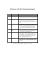
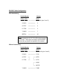
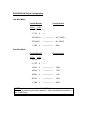
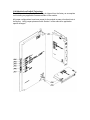
Corporate Office 1675 Chester Ave. Fourth Floor Bakersfield, CA 93301 (661) 716-5100 Phone (661) 716-5101 Fax Southeast US Sales Office 650 N Sam Houston Parkway E Suite 500 Houston, TX 77060 (713) 999-7565 Phone (713) 999-0823 Fax 3100/3101- CAS Revision 1.1 3150/3151- CAS Revision 1.1 September 1995 Teledyne CA Slave ______________________________________________________ USER MANUAL Please Read This Notice Successful application of the CAS card requires a reasonable working knowledge of the Allen-Bradley PLC or SLC hardware and the application in which the combination is to used. For this reason, it is important that those responsible for implementing the CAS satisfy themselves that the combination will meet the needs of the application without exposing personnel or equipment to unsafe or inappropriate working conditions. This manual is provided to assist the user. Every attempt has been made to assure that the information provided is accurate and a true reflection of the product's installation requirements. In order to assure a complete understanding of the operation of the product, the user should read all applicable Allen-Bradley documentation on the operation of the A-B hardware. Under no conditions will ProSoft Technology, Inc. be responsible or liable for indirect or consequential damages resulting from the use or application of the CAS product. Reproduction of the contents of this manual, in whole or in part, without written permission from ProSoft Technology, Inc. is prohibited. Information in this manual is subject to change without notice and does not represent a commitment on the part of ProSoft Technology, Inc. Improvements and/or changes in this manual or the product may be made at any time. These changes will be made periodically to correct technical inaccuracies or typographical errors. ProSoft Technology, Inc. 1995 TABLE OF CONTENTS I II Card Overview ..................................................................................................... 1 Configuring the Module........................................................................................ 3 2.1 Hardware Overview ...................................................................................... 3 2.2 Module Jumper Configurations ..................................................................... 3 2.2.1 3100/3101 for the 1771 Platform ............................................. 3 2.2.2 3150/3151 for the 1746 Platform ............................................. 4 2.3 Firmware Installation Procedure ( 3101 & 3151 ).......................................... 5 2.3.1 1771-DB Revision B Module .................................................... 5 2.3.2 1746-BAS Module .................................................................... 5 III Programming Considerations .............................................................................. 7 3.1 3100-CAS Overview ..................................................................................... 7 3.2 3150-CAS Overview ..................................................................................... 7 3.2.1 SLC Processor I/O Configuration ............................................. 7 3.3 Ladder Logic Considerations ........................................................................ 8 3.3.1 Operational Overview............................................................... 8 IV Theoretical Operation .......................................................................................... 9 4.1 Writing Data to the Module ........................................................................... 9 4.1.1 Communications Configuration [Block ID Code 255] ............... 10 4.1.2 Moving Data to the Module [Block ID Codes 0-19]................... 14 4.2 Reading Data from the Module ..................................................................... 14 4.2.1 Momentary/Continuous Control(Func 30, 31, 32 and 33) ........ 15 4.2.2 Setpoint Control (Func 34 and 35) ........................................... 16 4.2.3 Slave Error Code Table............................................................ 17 4.2.4 Error Status Codes................................................................... 19 V Protocol Commands ............................................................................................ 22 5.1 Data Read Functions .................................................................................... 22 5.1.1 Function 1 : Read Status Data ................................................. 22 5.1.2 Function 2 : Read Analog Data ................................................ 22 5.1.3 Function 3 : Read Meter Data .................................................. 22 5.1.4 Function 10: Read Frozen Analog Data................................... 22 5.1.5 Function 11: Read Frozen Meter Data ..................................... 22 5.1.6 Function 16: Read All Data ...................................................... 23 5.2 Control Commands From Master .................................................................. 23 5.2.1 Function 30/31 : Momentary Control Select/Operate ............... 23 5.2.2 Function 32/33 : Continuous Control Select/Operate............... 23 5.2.3 Function 34/35 : Setpoint Select/Operate ................................ 24 5.3 Freeze Data Commands............................................................................... 24 5.3.1 Function 43 : Freeze Meters .................................................... 24 5.3.2 Function 44 : Freeze Analogs .................................................. 24 5.3.3 Function 45 : Freeze Meters and Analogs ............................... 24 VI Hardware Diagnostics.......................................................................................... 25 6.1 3100/3101 PLC Platform .............................................................................. 25 6.2 3150/3151 SLC Platform .............................................................................. 26 VII Support, Service and Warranty..................................................................... 29 7.1 Technical Support......................................................................................... 29 7.2 Module Service and Repair........................................................................... 29 7.3 Warranty ....................................................................................................... 30 7.3.1 7.3.2 7.3.3 General Warranty Policy .......................................................... 30 Limitation of Liability................................................................. 30 Hardware Product Warranty Details......................................... 31 Appendices Appendix A PLC 5 Example Ladder Logic SLC Example Ladder Logic Appendix B Definitions of RS-232C Handshaking Signals RS-232 Cabling RS-422 and RS-485 cable Appendix C 3100/3101 Jumper diagrams 3150/3151 Jumper diagrams Appendix D Product Revision History I Card Overview The 3100/3150-CAS (“CA Slave”) product family allows Allen-Bradley 1771 and 1746 I/O compatible processors to easily interface with Teledyne CA protocol compatible hosts. The product is available from ProSoft Technology as either a module or a firmware solution. The firmware solution allows standard AllenBradley 1771-DB/B and 1746-BAS modules to be used as hardware platforms. The CAS product includes the following standard features: General Specifications • Two fully configurable serial ports, each capable of supporting the Teledyne CA Slave protocol. • RS-232C handshaking for SCADA radio/modem applications • RS-422/RS-485 compatible for multidrop applications with up to 32 slaves per port • Software configuration (From processor ladder logic) Slave Addr : 1 to 254 (255 is broadcast) Parity : None, odd, or even, Stop Bit : 1 or 2 Baud Rate : 300 TO 38,400 RTS to TxD : 0-65535 ms, 1 ms resolution RTS Off : 0-65535 ms, 1 ms resoluton • Response time The protocol drivers are written in Assembly and in a compiled higher level language. As such, the interrupt capabilities of the hardware are fully utilized to minimize delays, and to optimize the product's performance Protocol Driver Specifications • Protocol: Teledyne CA Slave • Function codes: 1 Read Status Data 2 Read Analog Data 3 Read Meter Data 10 Read Frozen Analog Values 11 Read Frozen Meter Data 16 Read All Data 20 Read Tank Data from RTU 30 Control - Momentary Select 31 Control - Momentary Operate 32 Control - Continuous Select 1 33 34 35 43 44 45 2 Control - Continuous Operate Setpoint - Select Setpoint - Operate Freeze Meters Freeze Analogs Freeze Meters/Analogs • Supports broadcast commands from Master • Register addressing Status : Analog : Meter : Tank : Up to 250 words Up to 250 words Up to 250 values (2 words per value) Up to 250 words • Supports Write Commands from Host Operates in both Direct or Indirect Modes Setpoint Select and Operate Control Point - Continuous and Momentary • Error Status and Communication Statistics for each port returned to the ladder processor II Configuring the Module 2.1 Hardware Overview When purchasing the CAS product, there are two available choices for each platform. These choices are as follows: ProSoft Cat Num PLC SLC 3100-CAS 3150-CAS 3101-CAS 3151-CAS Description Module provided by ProSoft Firmware only When purchasing the module from ProSoft Technology, many of the jumper configurations will have been factory set. When purchasing the firmware from ProSoft Technology and the Allen-Bradley module from another source, particular attention must be paid to hardware configuration. 2.2 Module Jumper Configurations The following section details the available jumper configurations for the 1771 and 1746 platform solutions. As needed, differences between the module based solutions and the firmware based solutions are highlighted. 2.2.1 3100/3101 for the 1771 Platform Following are the jumper positions for the 1771-DB Rev B module and the ProSoft Technology 3100-CAS module (See Appendix C for details on jumper locations): Jumper JW1 JW2 JW3 JW4 JW5 JW6 JW7 JW8 JW9 3100-CAS 3101-CAS N/A N/A N/A Not Used 16 Pt Not Used Enabled As Needed As Needed Enabled 32K PROM Turbo ASCII/ASCII 16 Pt Not Used Enabled As Needed As Needed JW1 Watchdog Enable / Disable Enable The position of this jumper does not affect the operation of the unit under normal operations. In order to enable the watchdog function, simply place the jumper in the Enabled position. JW2 PROM select 32K PROM The position of this jumper is very important to the successful operation of the module. In order to operate with our CAS EPROM, the jumper must be in the 32K PROM position. 3 JW3 Speed select (Normal / Turbo) Turbo The position of this jumper does not affect the operation of the unit under normal operations. Unless there are reasons not to operate in the Turbo mode, we recommend operating in the Turbo mode. JW4 Port 1 and 2 configuration Position A The position of this jumper set must be changed from the shipped default position (D) to the A position. Operation of the module will be unpredictable if the jumper set is not in the A position. A B C D PRT 1 = ASCII PRT 1 = PGM PRT 1 = PGM PRT 1 = PGM DEFAULT PRT 2 = ASCII PRT 2 = ASCII PRT 2 = DF1 PRT 2 = ASCII DH485 = PGM DH485 = RUN DH485 = DISABLED DH485 = RUN JW5 Backplane 8/16 point 16 Point The module has only been tested in the 8 and 16 point modes and has successfully operated in both positions. The 8 point mode should be used when installing the module into old PLC-2 installations. JW6 Port 2 Baud Rate Not Used This jumper is not used by the CAS firmware. All baud rate configuration is performed through the ladder logic data table. JW7 Battery Enable / Disable Enabled This jumper should be placed in the Enabled position when the module is powered up. Although not critical to the operation of the module, this will back up some data registers in the module during a power failure or reset. JW8/9 RS Configuration for Port 1 and 2 See options on module The default from factory is RS-232, but all options are supported by the CAS firmware 2.2.2 3150/3151 for the 1746 Platform Following are the jumper positions for the 1746-BAS module and the ProSoft Technology 3150-CAS module (See Appendix C for details on jumper locations): Jumper JW1 JW2 JW3 JW4 4 3150-CAS 3151-CAS As Needed As Needed N/A N/A As Needed As Needed 3-5, 4-6 1-3, 2-4 JW1/2 RS configuration for port 1 and 2 See Appendix C The default from factory is RS-232, but all options are supported by the CAS firmware JW3 Memory Selection 3-5, 4-6 When using the 3151 firmware solution with a 1746-BAS module, the EPROM is plugged into the User Socket. When in this configuration, it is essential that the jumper be in the correct position. With the 3150 module, this jumper will not affect operation of the product. JW4 Mode Configuration 1-3, 2-4 When using the 3151 firmware solution with a 1746-BAS module, it is essential that the jumper be in the correct position. With the 3150 module, this jumper will not affect operation of the product. 2.3 Firmware Installation Procedure ( 3101 & 3151 ) The following section details the available jumper configurations for the 1771 and 1746 platform solutions. As needed, differences between the module based solutions and the firmware based solutions are highlighted. 2.3.1 1771-DB Revision B Module The firmware installation steps are as follows: 1. Remove the card cover from the module 2. Plug the ProSoft Technology EPROM into the module's User Socket. Align the notches on the EPROM plastic carrier with the notches in the User socket. Make sure the EPROM is well seated 3. Replace the card cover 4. Turn the module over and locate the identification sticker in the unused indent. This sticker will be important should the module ever require service. 2.3.2 1746-BAS Module The firmware installation steps are as follows: 1. Plug the ProSoft Technology EPROM into the module's User Socket. Align the notches on the EPROM plastic carrier with the notches in the User socket. Make sure the EPROM is well seated 2. Remove the plastic lens cover from the 1746-BAS module and slip on the new cover provided with the firmware. Make sure the cover is firmly affixed to the module 5 Once the firmware has been installed and the module’s jumpers have been verified, the hardware is ready to be inserted into the I/O rack. 6 III Programming Considerations The CAS product family is very easy to implement. In both the PLC and the SLC platforms, the addition of several simple ladder rungs and the configuration of several configuration registers enables the module to operate as a very effective Modbus Master and Slave protocol interface. To ease initial contact with the product we have included a demonstration ladder program in Appendix A. An electronic copy of the ladder logic is available on disk with each product purchase. The following discussion covers the example logic located in Appendix A in an overview fashion. In addition, an explanation is given on how to adjust the ladder logic for a different application. 3.1 3100-CAS Overview Programming of the 3100-CAS is less complicated than our previous products for the PLC-5 environment. Once all of the jumpers have been setup and the chip installed, the module is ready to be configured and run. See Section 4 for details on configuring the module. In order to get the CAS operating with the example ladder logic only one modification should be necessary. The ladder logic BTR and BTW instructions may need to be modified to ensure that the Block Transfer instructions are set up for the correct rack and group (slot) address. 3.2 3150-CAS Overview The 3150-CAS is also very easy to get operational. After the lens cover and firmware are installed and the jumpers have been configured, the module is ready to be configured. See Section 4 for details on configuring the module. In order to implement the sample logic, the user must make sure that the correct processor and rack size match up. Also, should it be necessary to re-locate the CAS module, the user should be certain to configure the correct slot as a 1746-BAS 5/02 Configuration. 3.2.1 SLC Processor I/O Configuration When initially setting up the SLC program file, or when moving the module from one slot to another, the user must configure the slot to accept the CAS module. It is important that the slot containing the ProSoft module be configured as follows: - 1746-BAS module or enter 13106 for the module code - Configure the M0/M1 files for 64 words - Configure I/O for 8 words 7 The following is a step by step on how to configure these files using Allen-Bradley APS software. ICOM software users should follow similar steps. From the Main Menu: 1) Select the correct processor program and F3 for Offline programming 2) F1 for Processor Functions 3) F1 for Change Processor Modify the processor here if necessary (Note the CAS will only work with 5/02 or greater processors 4) F5 for Configure I/O Select 1746-BAS module for SLC 5/02 or greater, or enter 13106 for module code 5) F9 for SPIO Config when the correct slot is highlighted 6) F5 Advanced Setup 7) F5 for M0 file length - type in 64 and Enter 8) F6 for M1 file length - type in 64 and Enter Esc out and save configuration 3.3 Ladder Logic Considerations Those familiar with our 1100 family of products will observe that the ladder logic requirements for the CAS are substantially less. Much of the simplification of the ladder logic is due to: • The module now controls and feeds the Block ID numbers to the ladder logic. All ladder logic associated with manipulating the Block ID number has been eliminated The number of data registers transferred to/from the module is controlled through the setup of several configuration registers (See Section 4): 1. Write Data Block Count 3.3.1 Operational Overview On power up the module moves a 255 into Word 1 of the BTR data file. This is a signal that the module needs to receive configuration data before proceeding any further. Once the configuration is received the module will begin transferring data to and from the processor. 8 IV Theoretical Operation Data transfers between the processor and the ProSoft Technology module occur using the Block Transfer commands, in the case of the PLC, and M0/M1 data transfer commands, in the case of the SLC. These commands transfer up to 64 physical registers per transfer. The logical data length changes depending on the data transfer function. The following discussion details the data structures used to transfer the different types of data between the ProSoft Technology module and the processor. The term 'Block Transfer' is used generically in the following discussion to depict the transfer of data blocks between the processor and the ProSoft Technology module. Although a true Block Transfer function does not exist in the SLC, we have implemented a pseudo-block transfer command in order to assure data integrity at the block level. Examples of the PLC and SLC ladder logic are included in Appendix A. In order for the ProSoft Technology module to function, the PLC/SLC must be in the RUN/REM RUN mode to configure the module. Once configured, if the processor is in any other mode (Fault/PGM), the block transfers between the PLC and the module will time out, and a error condition will be returned to the Host. 4.1 Writing Data to the Module This section discusses how the transfer mechanism functions, and how to transfer data, command list and configuration data to the ProSoft module. Data transfer to the module from the processor is executed through the Block Transfer Write function. The different types of data which are transferred require slightly different data block structures, but the basic data structure is: Word 0 1-63 Description Block ID code Data In a PLC, the BTW length must be configured for 64 words, otherwise module operation will be unpredictable. Where: Block ID Code: A block identifier code between 0 and 255 in value. This code is used by the ProSoft module to determine what to do with the data block. Valid codes are: 9 Code 0-19 255 Description Module Data Memory Module Communication Configuration Data: The data to be written to the module. The structure of the data is dependent on the Block ID code. The following sections provide details on the different structures. 4.1.1 Communications Configuration [Block ID Code 255] The ProSoft Technology firmware communication parameters must be configured at least once when the card is first powered up, and any time thereafter when the parameters must be changed. On power up, the module enters into a logical loop waiting to receive configuration data from the processor. While waiting, the module sets the first word of the BTR buffer to 255, telling the processor that the module must be configured before anything else will be done. The module will continuously perform block transfers until the communications configuration parameters block is received. Upon receipt, the module will begin execution of the command list if present, or begin looking for the command list from the processor. Transferring the Communications Configuration Parameters to the module will force a reset of the communication port, as well as dropping DTR for 200 ms pulses to reset any attached hardware. The configuration data block structure which must be transferred from the processor to the module is as follows: Data Word Description Block ID Header = 255 Port 1 0 1 2 3 4 5 6 7 8 9 10 N[]:0 N[]:1 N[]:2 N[]:3 N[]:4 N[]:5 N[]:6 N[]:7 N[]:8 N[]:9 Port Configuration Word Slave Address Baud Rate RTS to TxD Delay RTS off Delay Message Response Timeout Inter-character timing Direct Control Not Used Not Used Port 2 10 11 12 13 14 15 16 17 18 19 N[]:10 N[]:11 N[]:12 N[]:13 N[]:14 N[]:15 N[]:16 N[]:17 N[]:18 N[]:19 Port Configuration Word Slave Address Baud Rate RTS to TxD Delay RTS off Delay Message Response Timeout Inter-character timing Direct Control Not Used Not Used System Configuration 20 N[]:20 Not Used 21 N[]:21 Data Block Count 22 N[]:22 Not Used 23 N[]:23 Not Used 24 N[]:24 Not Used 25 N[]:25 Block Transfer Delay Counter 26 N[]:26 Status Data File Length 27 N[]:27 Analog Data File Length 28 N[]:28 Meter Data File Length 29 N[]:29 Tank Data File Length Where: For Port 1 and Port 2 Port Configuration Word: This register contains several communication configuration parameters encoded into the word. These are as follows: Stop Bits: The number of stop bits to be used is defined as follows: Bits 13 12 0 0 0 1 1 x One stop bit Two stop bits Invalid Port Configuration Parity: The parity mode to be used by the module is defined by this word as follows: Bits 15 14 0 0 0 1 No parity Odd parity 11 1 0 1 1 Even parity Invalid Port Configuration Baud Rate: The baud rate at which the module is to operate. The baud rate is configured as follows: Value 0 1 2 3 4 5 6 7 Baud Rate 300 Baud 600 Baud 1200 Baud 2400 Baud 4800 Baud 9600 Baud 19200 Baud 38400 Baud The module’s two ports are limited to an upper baud rate of either 19200 or 38400 baud. The module cannot be configured with one port at 19200 and the other at 38400. If an attempt is made to configure the module in this fashion, a Port Configuration Error will be returned. RTS To TXD Delay: This value represents the time in 1 ms increments to be inserted between asserting RTS, and the actual transmission of data. The delay, if greater in duration than the hardware time delay associated with CTS, will override the CTS line until the time-out is complete. This configurable parameter is useful when interfacing with modem based devices, or anytime line noise must be allowed to subside before data is transmitted. RTS Off Delay: The value in this word represents the number of 1 ms time delay increments inserted after the last character is transmitted and before RTS is dropped. The module automatically inserts a one character width Off Delay, assuring that RTS does not drop until after the last character has been completely sent. Unless working under unusual conditions, this value will normally be configured with a value of 0. The maximum value to be used is 65535 (0xffff). Message Response Timout: This register represents the message response timeout period in 1 ms increments. This is the time which a port configured as a Master will wait before retransmitting a command if no response is received from the addressed slave. The value is set depending on the expected slave response times. 12 The allowable range of values is 0 to 65535(0xffff). If a zero value is entered, the module will default to a one second timeout value (1000 ms). Inter-character Timing: This register is used in situations where the end of message character timeout delay must be extended beyond the normal 3.5 character widths. The value entered represents the number of 1 ms intervals of ‘no transmission’ which will be counted prior to accepting a message. This parameter will be useful in satallite or packet radio installation where a data transmission may be split between two packets. Increasing this value beyond the system’s packet handling time will eliminate timeout errors. Direct Control : This parameter configures the module to accept the Control-Operate commands from a Master without first receiving a Control-Select command first. To disable the need for the Control-Select command, set this parameter to a value of 1. System Configuration Data Block Count: This value represents the number of 50 word data blocks which are to be transferred from the processor to the CAS Module. The module will use this value to return a BTW Block ID Number to the processor. The ladder logic can use this value to determine which data to move to the CAS via the Block Transfer Write. The maximum block count is 80. As an example, if a value of 5 is entered, the CAS will return Block ID numbers 0, 1, 2, 3, and 4 to the ladder logic (See Section 4.2). If a value greater than 80 is entered, a System Configuration Error is activated Block Transfer Delay Counter: This value is used by the module to slow down the block transfer loading between the module and the processor. Excessive Block Transfers can slow down the response time of the CAS’s communication ports. This parameter has been provided to allow the Block Transfer timing to be determined on an application basis. A value of 0 is normally used at the factory and is recommended as a starting point. Status Data File Length, Analog Data File Length, Meter Data File Length, and Tank Data File Length : These parameters allow the user to configure the logical size of the respective data tables in the module. Each table has a maximum size of 250 words, but can be downsized to any size below this. The size 13 optimization is useful under some implementations requesting all available data. 4.1.2 Moving Data to the Module [Block ID Codes 0-19] Writing register data to the ProSoft Technology module is a simple Block Transfer Write with Block ID codes from 0 to 19 followed by 50 words of data. The actual data table starts at word 0 (Block ID #0, word 0), and is built incrementally after this. For a maximum configuration, the Block down as follows: Data Type Block ID Status Data 0 to 4 Analog Data 5 to 9 Meter Data 10 to 14 Tank Data 15-19 ID codes are broken Max Size 250 words 250 words 250 words 250 words Assuming a smaller configuration with the following requirements: Status File 3 words Analog File 3 words Meter File 2 values (4 words) Tank File 2 words The data for this configuration will all map into Block ID#0. Assuming we are using N10 as the data file in the PLC, the data will map as follows: PLC Addr Type/Addr N10:0 Status - Word 0 N10:1 Status - Word 1 N10:2 Status - Word 2 N10:3 Analog - Word 0 N10:4 Analog - Word 1 N10:5 Analog - Word 2 N10:6 Meter - Value 0 high N10:7 Meter - Value 0 low N10:8 Meter - Value 1 high N10:9 Meter - Value 1 low N10:10 Tank - Word 0 N10:11 Tank - Word 1 With this configuration, the user need only send Block ID #0 to the module. 4.2 Reading Data from the Module This section discusses how to get data written to the ProSoft module by a Master into the PLC. Supported TCAP Functions include 30, 31, 32, 33, 34, and 35. The transfer of data from the ProSoft Technology module to the processor is executed through the Block Transfer Read function. Three 14 basic different types of data are read from the module into the processor; • Module Status Data [ Block ID 0 ] • Write Data from Host [ Block ID 1, 2 or 4 ] • Configuration Request [ Block ID 255 ] The data structure for the block transfer depends on the type of block data. The following sections detail the different types of data. In a PLC, the BTR length must be configured for a length of 64 words, otherwise module operation will be unpredictable The ladder logic must be programmed to look at the BTR buffer, decode several words, and then take action. The BTR buffer definition is: Word 0 1 2-62 Description Block ID Code BTW Block ID Number Data Where: BTW Block ID Number: The module returns this value to the processor to be used to enable the movement of register data and command list blocks to the module. The BTW Block ID number is developed by the module based on the parameters entered in parameter 22 of Block 255 (See Section 4.1.1). This value is intended to only be a suggestion and to ease the ladder logic programming requirements. If it is desired to develop a different data transfer series, this may be easily accomplished in ladder logic. Data: The contents of the module’s Register Data space (0 - 999). This data will contain data received from the slaves and data moved from the processor. The values will be 16 bit register values, and should be placed into integer files. Note that the user application ladder logic controls the placement and use of the data registers. 4.2.1 Momentary/Continuous Control(Func 30, 31, 32 and 33) When a Momentary or a Continuous Control command is received from a Master, the ProSoft module transfers the command immediately to the BTR buffer for the ladder logic to work with. The Control command will not be transferred to the buffer unless the Operate Command (31 or 33) is received immediately after a Select Command (30 or 32), or if Direct Control is enabled in the module's configuration. The ladder logic must provide the logic to enable the momentary action. The ProSoft module will not provide the command to the PLC to clear or reset the bit). 15 The ladder logic must be programmed to look at the BTR buffer, decode several words, and then take action. The BTR buffer definition, as it pertains to the Momentary and Continuous Control commands, is: WORD DESCRIPTION 0 Control Type 1 = Momentary Control 2 = Continuous Control BTW Block ID Number Bit Addressed Control Action 1 2 3 Control Type: Word 0 of the BTR buffer is used to tell the PLC what type of Control action has been commanded from the Master. When the value is equal to 1, a new Momentary Control command has been received. When the value is equal to 2, a new Continuous Control command has been received. With simple ladder logic to decode this value, the appropriate word/bit can be acted upon. The exact location that the PLC will act upon is determined by the next two words. Bit Address: The Bit Address represents the bit which will be acted on within the word addressed in the previous parameter. Control Action: The action commanded by the Master is transferred in this word. When the value is a 0, the addressed bit is to be reset, and when the value is a 1, the addressed bit is to be set. The value is always set to one for Momentary Control. 4.2.2 Setpoint Control (Func 34 and 35) When a Setpoint Control command is received from a Master, the ProSoft module transfers the command immediately to the BTR buffer for the ladder logic to work with. The Setpoint Control command will not be transferred to the buffer unless the Operate Command (35) is received immediately after the Select Command (34), or if Direct Control is enabled in the module's configuration. WORD DESCRIPTION 0 Control Type 4 = Setpoint Control BTW Block ID Number Word Addressed Setpoint Value 1 2 3 Where: 16 Contorl Type: Word 0 of the BTR buffer is used to tell the PLC what type of Control action has been commanded from the Master. When the value is equal to 4, a new Setpoint Control command has been received. With simple ladder logic to decode this value, the appropriate action can be taken. Word Address: This value is used by the ladder logic to determine which word to act upon. Setpoint Value: The data value received from the Master. The values will be 12 bit value, and should be placed into an integer or BCD file. 4.2.3 Slave Error Code Table The CAS Module monitors the status of all Slave port commands. This status is communicated to the processor in the form of a Slave Error Code Table. The Slave Error Code Table is initialized to zero on power up, and every time the module receives the 255 configuration data block. The Slave Error Table is a 20 word block returned to the processor whenever the BTR Block ID is 0. WORD DESCRIPTION 0 1 2 BTR Block ID 0 = Module Status BTW Block ID Number Begin Status Data Block The structure of the data block is as follows: WORD DESCRIPTION Port 1 0 Port Scan/Error status 1 Last transmitted error condition 2 Total Messages to this slave 3 Total Msg responses from this slave 4 Total Msgs seen by this slave Port 2 5 Port Scan/Error status 6 Last transmitted error condition 7 Total Messages to this slave 8 Total Msg responses from this slave 9 Total Msgs seen by this slave System Information 10-11 Product Name (ASCII) 12-13 Revision (ASCII) 14 (blank) 15 Production Run Number 16-19 Spare 17 Where: Port Scan/Error Status: This register contains the port’s Scan status in the upper byte and the port’s current error status in the lower byte. The Scan Status is encoded in the upper byte as follows: Bit Description 13 Status Data scan 14 Analog Data scan 15 Read All Data scan Port error status codes values are detailed in the following section. Last Transmitted Error Code: This value is the last error code transmitted to the master by this slave port. Error codes which can be expected in this field are 0, 1, 2, 3, and 6. The field will only be cleared by re configuring the module (Block ID 255). Total Messages to This Slave: This value represents the total number of messages that have matched this slaves address on this port, whether the slave actually determined them to be good (worthy of response) or not. Total Message Responses From This Slave: This value represents the number of good (non-error) responses that the slave has sent to the master on this port. The presumption is that if the slave is responding, the message was good. Total Messages Seen By This Slave: This value represents the total number of commands seen by the slave on this port, regardless of the slave address. All counters in the Slave Error Table will rollover to 0 after reaching 65535 Product Name: These two words represent the product name of the module in an ASCII representation. In the case of the CAS product, the letters ‘ CAS ‘ should be displayed when placing the programming software in the ASCII data representation mode. Revision : These two words represent the product revision level of the firmware in an ASCII representation. An example of the data displayed would be ‘1.40’ when placing the programming software in the ASCII data representation mode. Blank: Not used at this time 18 Production Run Number: This number represents the ‘batch’ number that your particular chip belongs to. This number should appear as a number equal or greater than 2. This should help the factory determine when the User’s chip was created. 4.2.4 Error Status Codes The Error Codes returned in the Slave and Master Error Code Tables reflect the outcome of the commands and responses executed by the module. Note that in all cases, if a zero is returned, there was not an error. Valid Error Status Codes are as follows: Code 0 Description All OK The module is operating as desired. 1 Illegal Function An illegal function code request has been received from the master 2 Illegal Data Address The address, or the range of addresses, covered by a request from the master are not within allowed limits 3 Illegal Data Value The value in the data field of the command is not allowed. 6 Module Busy The module busy status code is returned when a write command from the master has not yet been completed when a second write command is received 7 Illegal Command An illegal function code request has been received from the master 9 Data Sequence Error The Operate command was received out of sequence (not immediately after a Select) 16 Port Configuration Error If this value is returned from the module, one or both of the serial ports have been misconfigured. To determine the exact source of the problem, verify the following: Parity configuration 19 18 System Configuration Error If this value is returned from the module, one of the system configuration parameters has been determined to be out of range. To determine the exact source of the problem, verify the following: Read Block Count Write Block Count Command Block Count Slave Error Pointer Master Error Pointer 254 Checksum Error The slave determined that the message checksum was in error, and therefore discarded the message 255 20 Stop bit configuration Baud rate configuration Start Input Register Address Start Output Register Address TX Hardware Time-out A time-out has occurred in the transmission of the command from the master, and the command has been aborted. This error is usually an indication that the CTS signal is not being received by the module. (This page intentionally left blank) 21 V Protocol Commands The ProSoft Technology CAS module communication driver supports several data read and write commands. When configuring an application, it may be important to understand how the commands function in order to determine how to structure the application data. 5.1 22 Data Read Functions As stated in earlier sections, the data sent to the master is taken directly out of the module's memory at the time a response is sent. 5.1.1 Function 1 : Read Status Data The module supports access to a total of up to 250 words of status data from the ladder processor. In TCAP vernacular, the 'Start Card Address' is used to identify the starting word, and the 'Number of Cards' is used to identify the number of words. 5.1.2 Function 2 : Read Analog Data The module supports access to a total of up to 250 words of analog data from the ladder processor. In TCAP vernacular, the 'Start Card No.' and the 'Start Point No.' (Upper and lower four bits, respectively) are treated as one byte to develop a starting word address, while the 'Number of Analogs' is used to determine the number of words to be returned to the Master. 5.1.3 Function 3 : Read Meter Data The module supports access to a total of up to 250 words Meter data (125 meter readings) from the ladder processor. TCAP vernacular, the 'Starting Meter Number' is used determine the first word to be accessed, while the 'Number meters to be returned' value is used to determine the number words to be returned to the Master. of In to of of 5.1.4 Function 10: Read Frozen Analog Data This function provides the Master access to the contents of up to a 250 word buffer maintained in the module. This buffer contains the analog values stored as a result of the last 'Freeze Analogs' command (44/45) received from the Master. It is addressed in the same fashion as Function 2. 5.1.5 Function 11: Read Frozen Meter Data This function provides the Master access to the contents of up to a 250 word buffer maintained in the module. This buffer contains the meter values stored as a result of the last 'Freeze Meters' command (43/45) received from the Master. It is addressed in the same fashion as Function 3. 5.1.6 5.2 Function 16: Read All Data This general purpose command is partially supported in the ProSoft Module. The following Data Select Types are available from the module: - Status Inputs (Data Select bit 7) - Analog Inputs (Data Select bit 6) - Meter Accumulator Inputs (Data Select bit 5) The command allows up to 63 analog values to be requested and up to 7 meters. If no data quantity is requested (length fields are zero), all of the available data, as defined in the Configuration Parameters, will be returned. When the Status Inputs are requested, the full status table is returned. Control Commands From Master When Control commands are received from a Master, their action is immediately communicated to the PLC/SLC for action. No modification is made directly to the ProSoft Module's memory as a result of a Control Command. In order for any Control action to be reflected in the module's memory, it must be transferred within the Status Data block. 5.2.1 Function 30/31 : Momentary Control Select/Operate These control commands are recognized by the module. If the Operate command is received out of sequence (must be received in next communication sequence after Select command), the command is disregarded. If the module is configured for Direct Control, then the Master need only send the Operate command for action to occur. In TCAP vernacular, the 'Card Number' and the 'Point Number' are combined to identify the bit number. The action value is always set to 1, so the action will always be to set a bit true momentarily. With this decoding, indirect addressing can be used(in PLC5) to decode the addressed bit: B13 / [N7:x] where N7:x is Word 1 of the BTR data block from the module. 5.2.2 Function 32/33 : Continuous Control Select/Operate These control commands are recognized by the module. If the Operate command is received out of sequence (must be received in next communication sequence after Select command), the command is disregarded. If the module is configured for Direct Control, then the Master need only send the Operate command for action to occur. In TCAP vernacular, the 'Card Number' and the 'Point Number' are combined to identify the bit number. With 23 this decoding, indirect addressing can be used(in PLC5) to decode the addressed bit: B13 / [N7:x+1] where N7:x is Word 1 of the BTR data block from the module. 5.2.3 5.3 Function 34/35 : Setpoint Select/Operate These control commands are recognized by the module. If the Operate command is received out of sequence (must be received in next communication sequence after Select command), the command is disregarded. If the module is configured for Direct Control, then the Master need only send the Operate command for action to occur. In TCAP vernacular, the 'Card Number' (upper 7 bits) is combined with the 'Point Number' (low 1 bit) to obtain an effective addressing range of 256 registers. The value written to the ladder logic limited to a 12 bit value by the protocol specification. Freeze Data Commands These general purpose commands are used to initiate the movement of data within buffers in the ProSoft Technology module. These buffers are maintained for access by related read commands, discussed above. The module one-shots the freeze commands from the Master, enable the movement of the buffers only if the Master has previously issued a read to the previously frozen buffer. 24 5.3.1 Function 43 : Freeze Meters Moves the Meter Data buffer to the Freeze Meter buffer. 5.3.2 Function 44 : Freeze Analogs Moves the Analog Data buffer to the Freeze Analog buffer. 5.3.3 Function 45 : Freeze Meters and Analogs Moves the Meter Data buffer and the Analog Data buffer to their respective Freeze buffers. VI Hardware Diagnostics Several hardware diagnostics capabilities have been implemented using the LED indicator lights on the front of the module. The following sections explain the meaning of the individual LEDs for both the PLC and the SLC platforms. 6.1 3100/3101 PLC Platform The PLC platform CAS product is available in two forms: • • ProSoft Technology Module (3100-CIM) Allen-Bradley 1771-DB Revision B card Operation of the two modules is nearly identical, but labeling on the status LEDs is different. The following table documents the differences between LEDs on the two hardware platforms and explains the operation of the LEDs. ProSoft CIM Card ACTIVE CFG ERR1 TXD1 RXD2 ¡¡ ¡¡ ¡¡ ¡¡ ¡¡ A-B 1771-DB Rev B Card FLT BPLN ERR2 TXD2 RXD2 ACTIVE DH485 LED1 PT1X PT1R ¡¡ ¡¡ ¡¡ ¡¡ ¡¡ FLT BTLO LED2 PT2X PT2R Table 6.1 : PLC Platform LED Indication ProSoft CIM ACT A-B DB/B ACT Color Green Status Blink (Fast) On Blink ( 1/Sec) Off FLT FLT Red Off On Indication Normal state : The module is operating normally and successfully Block Transferring with the PLC The module is receiving power from the backplane, but there may be some other problem Indicates the module has somehow entered the Basic Programming Mode. Verify jumper JW4 (DB/B only) configuration. If all are correct, then contact the factory The module is attempting to Block Transfer with the PLC and has failed. The PLC may be in the PGM mode or may be faulted Normal State : No system problems are detected during background diagnostics A system problem was detected during background diagnostics. Please contact factory for technical support 25 Table 6.1 : PLC Platform LED Indication (Cont’d) ProSoft Name CFG DB Name DH485 Color Green Status Off Blink On BPLN BTLO Red Off On ERR1 ERR2 LED1 LED2 Amber Off Blink On 6.2 Indication Normal state : No configuration related activity is occurring at this time This light blinks every time a Module Configuration block (ID = 255) is received from the processor ladder logic The light is on continuously whenever a configuration error is detected. The error could be in the Port Configuration data or in the System Configuration data. See Section 4 for details Normal State : When this light is off and the ACT light is blinking quickly, the module is actively Block Transferring data with the PLC Indicates that Block Transfers between the PLC and the module have failed.( Not activated in the initial release of the product) Normal State : When the error LED is off and the related port is actively transferring data, there are no communication errors Periodic communication errors are occurring during data communications. See Section 4 to determine the error condition This LED will stay on under several conditions: • CTS input is not being satisfied • Port Configuration Error • System Configuration Error • Unsuccessful comm on CAS slave • Recurring error condition on CAS master Tx1 Tx2 PT1X PT2X Green Blink The port is transmitting data. Rx1 Rx2 PT1R PT2R Green Blink The port is receiving data 3150/3151 SLC Platform The PLC platform CAS product is available in two forms: • • ProSoft Technology Module (3150-CIM) Allen-Bradley 1746-BAS card Operation of the two modules is nearly identical and labeling on the status LEDs is the same. The following table documents the differences 26 between LEDs on the two hardware platforms and explains the operation of the LEDs. 3150-CAS COMMUNICATIONS ACT FAULT CFG BPLN PRT1 ERR1 PRT2 ERR2 Table 6.2 : SLC Platform LED Indication LED Name ACT Color Green Status Blink (Fast) On Blink ( 1/Sec) Off FLT Red Off On CFG Green Off Blink On BPLN Red Off On Indication Normal state : The module is operating normally and successfully Block Transferring with the SLC The module is receiving power from the backplane, but there may be some other problem Indicates the module has somehow entered the Basic Programming Mode. Verify jumper JW3 (BAS only) configuration. If all are correct, then contact the factory The module is attempting to Block Transfer with the SLC and has failed. The SLC may be in the PGM mode or may be faulted (Not in initial release) Normal State : No system problems are detected during background diagnostics A system problem was detected during background diagnostics. Please contact factory for technical support Normal state : No configuration related activity is occurring at this time This light blinks every time a Module Configuration block (ID = 255) is received from the processor ladder logic The light is on continuously whenever a configuration error is detected. The error could be in the Port Configuration data or in the System Configuration data. See Section 4 for details Normal State : When this light is off and the ACT light is blinking quickly, the module is actively Block Transferring data with the SLC Indicates that Block Transfers between the SLC and the module have failed 27 Table 6.2 : SLC Platform LED Indication (Cont’d) LED Name ERR1 ERR2 Color Amber Status Off Blink On TxRx1 TxRx2 28 Green Blink Indication Normal State : When the error LED is off and the related port is actively transferring data, there are no communication errors Periodic communication errors are occurring during data communications. See Section 4 to determine the error condition This LED will stay on under several conditions: • CTS input is not being satisfied • Port Configuration Error • System Configuration Error • Unsuccessful comm on CAS slave • Recurring error condition on CAS master The port is communicating, either transmitting or receiving data VII Support, Service and Warranty 7.1 Technical Support ProSoft Technology survives on its ability to provide meaningful support to its customers. Should any questions or problems arise, please feel free to contact us at: Factory/Technical Support Corporate ProSoft Technology, Inc. 9801 Camino Media Suite 105 Bakersfield, CA 93311 (805) 664-7208 (800) 326-7066 (805) 664-7233 (fax) Before calling for support, please prepare yourself for the call. In order to provide the best and quickest support possible, we will most likely ask for the following information (you may wish to fax it to us prior to calling): 1. Product Serial and Version Number 2. Configuration Information - Communication Configuration - Master Command List - Jumper positions 3. System hierachy 4. Physical connection information - RS-232, 422 or 485 - Cable configuration 5. Module Operation - Block Transfers operation - LED patterns A BBS is available for the latest information on updates and new products. The phone number for the Bulletin Board is (805) 664-7234. Access is available 24 hours per day. In addition to 24 hour access to the BBS, an after-hours answering service (on the Bakersfield number) allows pager access to one of our qualified technical and/or application support engineers at any time to answer the questions that are important to you. 7.2 Module Service and Repair The CAS card is an electronic product, designed and manufactured to function under somewhat adverse conditions. As with any product, through age, misapplication, or any one of many possible problems, the card may require repair. 29 When purchased from ProSoft Technology, the module has a one year parts and labor warranty according to the limits specified in the warranty. Replacement and/or returns should be directed to the distributor from whom the product was purchased. If you need to return the card for repair, it is first necessary to obtain an RMA number from ProSoft Technology. Please call the factory for this number and display the number prominently on the outside of the shipping carton used to return the card. 7.3 Warranty 7.3.1 General Warranty Policy ProSoft Technology, Inc. (Hereinafter referred to as ProSoft) warrants that the Product shall conform to and perform in accordance with published technical specifications and the accompanying written materials, and shall be free of defects in materials and workmanship, for the period of time herein indicated, such warranty period commencing upon receipt of the Product. This warranty is limited to the repair and/or replacement, at ProSoft's election, of defective or non-conforming Product, and ProSoft shall not be responsible for the failure of the Product to perform specified functions, or any other nonconformance caused by or attributable to: (a) any misapplication of misuse of the Product; (b) failure of Customer to adhere to any of ProSoft's specifications or instructions; (c) neglect of, abuse of, or accident to, the Product; or (d) any associated or complementary equipment or software not furnished by ProSoft. Limited warranty service may be obtained by delivering the Product to ProSoft and providing proof of purchase or receipt date. Customer agrees to insure the Product or assume the risk of loss or damage in transit, to prepay shipping charges to ProSoft, and to use the original shipping container or equivalent. Contact ProSoft Customer Service at (805) 664-7208 for further information. 7.3.2 Limitation of Liability EXCEPT AS EXPRESSLY PROVIDED HEREIN, PROSOFT MAKES NO WARRANT OF ANY KIND, EXPRESSED OR IMPLIED, WITH RESPECT TO ANY EQUIPMENT, PARTS OR SERVICES PROVIDED PURSUANT TO THIS AGREEMENT, INCLUDING BUT NOT LIMITED TO THE IMPLIED WARRANTIES OF MERCHANT ABILITY AND FITNESS FOR A PARTICULAR PURPOSE. NEITHER PROSOFT OR ITS DEALER SHALL BE LIABLE FOR ANY OTHER DAMAGES, INCLUDING BUT NOT LIMITED TO DIRECT, INDIRECT, INCIDENTAL, SPECIAL OR CONSEQUENTIAL DAMAGES, WHETHER IN AN ACTION IN CONTRACT OR TORT (INCLUDING NEGLIGENCE AND STRICT LIABILITY), SUCH AS, BUT NOT LIMITED TO, LOSS OF ANTICIPATED PROFITS OR BENEFITS RESULTING FROM, OR ARISING OUT OF, OR IN CONNECTION WITH THE USE OR FURNISHING OF EQUIPMENT, PARTS OR SERVICES HEREUNDER OR THE PERFORMANCE, USE OR INABILITY TO USE THE SAME, EVEN IF PROSOFT OR ITS DEALER'S TOTAL LIABILITY EXCEED THE PRICE PAID FOR THE PRODUCT. Where directed by State Law, some of the above exclusions or limitations may not be applicable in some states. This warranty provides specific legal rights; other rights that vary from state to state may also exist. This warranty shall not 30 be applicable to the extent that any provisions of this warranty is prohibited by any Federal, State or Municipal Law that cannot be preempted. 7.3.3 Hardware Product Warranty Details Warranty Period : ProSoft warranties hardware product for a period of one (1) year. Warranty Procedure : Upon return of the hardware Product ProSoft will, at its option, repair or replace Product at no additional charge, freight prepaid, except as set forth below. Repair parts and replacement Product will be furnished on an exchange basis and will be either reconditioned or new. All replaced Product and parts become the property of ProSoft. If ProSoft determines that the Product is not under warranty, it will, at the Customer's option, repair the Product using current ProSoft standard rates for parts and labor, and return the Product freight collect. 31 (This page intentionally left blank) 32 APPENDIX A-1 PLC-5 Example Ladder Logic APPENDIX A-2 SLC-5/02 Example Ladder Logic APPENDIX B CABLE DIAGRAMS RS-232 RS-422 RS-485 Definitions of RS-232C Handshaking Signals SIGNAL TXD TITLE Transmitted Data DESCRIPTION Carries serialized data. It is an output from the module RXD Received Data RXD is serialized data input to the module. RXD is isolated from the rest of the circuitry on the modules RTS Request To Send RTS is a request from the module to the modem to prepare to transmit. RTS is turned ON when the module has a message to transmit. Otherwise, RTS is OFF CTS Clear to Send CTS is a signal from the modem to the module that indicates the carrier is stable and the modem is ready to transmit. The module will not transmit until CTS is on. If CTS is turned off during transmission, the module will stop transmitting until CTS is restored DTR Data Terminal Ready DTR is a signal to the modem to indicate that the module is operational and ready for communication. The module will continually assert DTR DSR Data Set Ready DSR is a signal from the modem to the module to indicate that the modem is operational and ready for communication. The CAS product family does not require the DSR signal to operate correctly. This signal is disregarded by the CAS units. DCD Data Carrier Detect DCD is a signal from the modem to the module to indicate that the carrier from another modem is being sensed on the link. This signal is disregarded by the CAS units. (Excerpted form Allen-Bradley Publication 1785.6.5.2) RS-232C Cable Configuration With Handshaking : ProSoft Module Modem 25-Pin 9-Pin 25-Pin 2 TxD 3 ------------------2 (Verify pins 2 and 3) 3 RxD 2 ------------------- 3 4 RTS 7 ------------------- 4 5 CTS 8 ------------------- 5 7 GND 5 ------------------- 7 20DTR 4 ------------------- 20 Note Do not connect pins 14, 16, 18, or 25 on the connector to a modem. These pins are used by the RS-422/485 drivers and may impact the operation of the modem. Without Handshaking : ProSoft Module Device 25-Pin 9-Pin 25-Pin 2 TxD 3 ------------------- 2 RxD (Verify pins 2 and 3) 3 RxD 2 ------------------- 3 TxD 4 RTS 7 ----| ----- 5 CTS 8 ----- 4 RTS | ----- 5 CTS ---- 6 DSR | ----- 20 DTR 7 GND 5 -------------------- 7 GND RS-422/RS-485 Cable Configuration Two Wire Mode : ProSoft Module 25-Pin 9-Pin 4 RTS 7 5 CTS 8 Foreign Device ---| ---- 14TxRxD+9 -------------------- A(+) TxRxD+ 25TxRxD-1 -------------------- B(-) TxRxD- 7 GND -------------------- GND 5 Four Wire Mode : ProSoft Module 25-Pin 9-Pin 4 RTS 7 5 CTS 8 Foreign Device ---| ---- 14TxD+ 9 -------------------- RxD+ 16RxD+ 6 -------------------- TxD+ 18RxD- 2 -------------------- TxD- 25TxD- 1 -------------------- RxD- 7 GND 5 -------------------- GND NOTES: If communication in RS-422/RS-485 do not work, despite all attempts, try switching termination polarities. Some manufacturers interpret (+) and (-) differently. APPENDIX C Jumper Configurations 1771 Platform - 3100 Module - 1771-DB Revision B Module 1746 Platform - 3150 Module - 1746-BAS Module 3100 Module from ProSoft Technology The 3100 module from ProSoft Technology is shipped from the factory as a complete unit including any applicable firmware resident in the module. All jumper configurations have been preset for the module to pass a functional test at the factory. Verify jumper placement with Section 2 of the manual for application specific changes. 1771-DB Revision B Module from Allen-Bradley The 3101 firmware solution is installed into an Allen-Bradley 1771-DB Revision B module. To successfully operate the module, the firmware must be installed and the jumpers must be configured. Section 2 of the manual details the correct positioning for the jumpers. In addition, Section 2 also details the steps necessary to install the firmware chip. The ProSoft Technology firmware is shipped in a plastic carrier to help minimize erroneous installations. The following diagrams help to identify the physical location of the jumpers on the module and location of the firmware socket. 1771-DB Revision B Module from Allen-Bradley (Cont’d) Firmware installation diagrams: Firmware Socket Location (SKT1) Firmware Installation 3150 Module from ProSoft Technology Jumpers JW 1 and JW 2: Port 1 and Port 2 Configuration Both of these ports operate electrically in a very similar fashion. The following diagrams depict the appropriate jumper placement. Jumpers JW 3 and JW 4 are not used by 3150 module 1746-BAS Module from Allen-Bradley Jumpers JW 1 and JW 2: Port 1 and Port 2 Configuration Both of these ports operate electrically in a very similar fashion. The following diagrams depict the appropriate jumper placement. 1746-BAS Module from Allen-Bradley (Cont’d) Jumpers JW 3 : Memory Selection Jumper This jumper must be selected for the 1747-M4 UVPROM. The jumper must be as follows: Jump 4 to 6 Jump 3 to 5 1746-BAS Module from Allen-Bradley (Cont’d) Jumpers JW 4 : Module Port Configuration This jumper must be selected as follows: Jump 2 to 4 Jump 1 to 3 APPENDIX D Product Revision History (This page intentionally left blank) Product Revision History 09/05/95 Revision 1.10 Initial release of product Started w/ CAS code and original CA Slave Driver code 04/04/96 Revision 1.11 Minor Upgrade Modified the CAS code for SLC to support the use of DSR signal instead of DCD. The SLC platform hardware does not have a DCD signal (This page intentionally left blank)