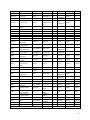
1
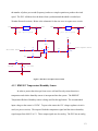
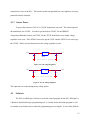
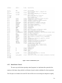
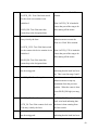
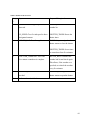
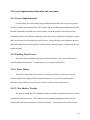
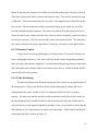
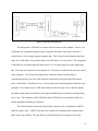
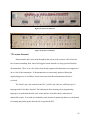
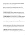
Table 1: List of Materials
4.0
Weather Subsystem
4.1
Sensors
4.1.1 TE525 Rain Gauge
In order to protect the telescope from precipitation a rain sensor is incorporated into the
system. USU already has the TE525 rain gauge sensor so that is being used. The TE525 works
as a simple switch. When rain fills up the tipper, it tips and closes a switch. Each tip represents
0.01 inches of rain have fallen. The input to the TE525 will be 5VDC. The output signal will be
a 5V pulse wave which will be directly inputted into the PLC’s TTL logic board where it will
count the pulses (frequency). The PLC will count the pulses over a predetermined amount of
time to determine if it is safe for the dome to open (see Weather Research section). During the
winter a snowfall adaptor will be placed on top of the TE525 which will melt the snow to have
the TE525 work if it were raining.
4.1.2 03101 R.M. Wind Sensor
In order to protect the telescope from debris in the air an anemometer is incorporated into
the system. The anemometer that is being used is the 03101 R.M. Wind Sensor. This sensor
requires no input voltage to power the sensor; it generates its own AC sine wave. This, however,
is a minor problem as the PLC cannot accept a low frequency sine wave input. To convert the
sine wave output to a square wave a LM358 operational amplifier and a 2N3904 BJT were used.
The operational amplifier is used in an inverting non-linear configuration with a gain of ten. The
BJT is connected to the output of the op-amp to generate the 5V pulse wave. The PLC counts
12